IEEE TRANSACTIONS ON MOBILE COMPUTING 1
Coverage Optimization with
a Dynamic Network of Drone Relays
Edgar Arribas, Vincenzo Mancuso, Vicent Cholvi
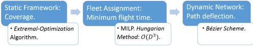
Abstract—The integration of aerial base stations carried by drones in cellular networks offers promising opportunities to enhance the connectivity enjoyed by ground users. In this paper, we propose an optimization framework for the 3–D placement and repositioning of a fleet of drones with a realistic inter-drone interference model and drone connectivity constraints. We show how to maximize network coverage by means of anextremal-optimizationalgorithm. The design of our algorithm is based on a mixed-integer non-convex program formulation for a coverage problem that is NP-Complete, as we prove in the paper. We not only optimize drone positions in a 3–D space in polynomial time, but also assign flight routes solving an assignment problem and using a strong geometrical tool, namelyB´ezier curves, which are extremely useful for non-uniform and realistic topologies. Specifically, we propose to fly drones followingB´ezier curves to seek the chance of approaching to clusters of ground users. This enhances coverage over time while users and drones move. We assess the performance of our proposal for synthetic scenarios as well as realistic maps extracted from the topology of a capital city. We demonstrate that our framework is near-optimal and usingB´ezier curvesincreases coverage up to47%while drones move.
Index Terms—Aerial networks, Relay, UAV, Mobile networks, Optimization,B´ezier curves.
F
1
INTRODUCTION
C
ELLULARnetworks are experiencing deep changes due to the advent of 5G technologies [1]. The need of flexible and adaptive management solutions, to address a highly mutable density of users, has allowed novel commu-nication paradigms to emerge, e.g., device-to-device (D2D) communications, smart relay and the use of reconfigurable backhaul links controlled by Software-Defined Networking (SDN) tools [2]. Since the interest for mobile and topology-adaptive relays is now reviving—due to the techniques that make it doable in operational networks rather than just in theoretic speculations—in this paper we focus on the analysis of a key use-case: a fleet of coordinated drones carryingaerialrelays meant to optimize cellular coverage.The availability of broadband backhaul links allows manned and unmanned vehicles (e.g., drones) to carry mo-bile relays. The use of momo-bile relays brings unique opportu-nities to deploy adaptive and flexible networks that provide connectivity where fixed infrastructures lack operational connectivity [3]. Basic advantages from relays, like the reuse of cellular bands, have been studied by several authors, e.g., by Guo and O’Farrel [4], whose results illustrate how wire-less networks are mainly impaired by interference. Other studies confirm that interference is commonly the main limiting factor also for the performance of relays operated over D2D sidelinks [5]. Hence, relays need to use dedicated frequencies in practice, which has the further advantage of simplifying resource allocation schemes [6].
Thus, we study the case of drones as relay stations trans-mitting on orthogonal frequencies with respect to ground base stations. However, due to limited spectrum resources,
• E. Arribas is with IMDEA Networks Institute and Universidad Carlos III de Madrid (UC3M), Madrid, Spain. E-mail: [email protected]
• V. Mancuso is with IMDEA Networks Institute, Madrid, Spain. E-mail: [email protected]
• V. Cholvi is with Universitat Jaume I (UJI) de Castell´o, Spain. E-mail: [email protected]
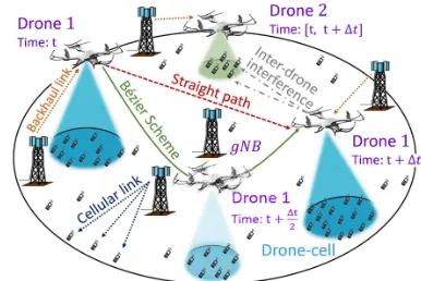
Figure 1. Reference scenario: multi-drone-aided network.
dronesdointerfere with each other and interference cannot be neglected both in users access and backhaul links, as we study in our work. These aspects have not been studied so far because existing works on drone relays focused on the optimal placement of a single drone in isolation, mainly under static scenarios, and neglect connectivity issues in the backhaul links between drones and ground base stations.
Although relay optimization can be used to support quality of service (QoS) in many different aspects, here we focus on providing support to user applications that require high probability to find the network available. This is important to guarantee essential communication means for voice and real time data communications. It is even more important for addressing the case of safety/emergency events and whenever notifying the status of users and having basic real-time communication tools is vital. These scenarios require to maximize the number of users that can be served, rather than maximizing on the allocated data rate or on the aggregate network rate. Therefore, we refer to QoS in terms of network availability with basic guaranteed rate.
IEEE TRANSACTIONS ON MOBILE COMPUTING 2
as depicted in Figure 1. Drones are coordinated yet they mutually interfere. We optimize coverage based on the QoS offered by drones under realistic path-loss models for line-of-sight (LoS) and non-LoS (NLoS) communications and interference. Considering interference is key because it re-sults in radically different coverage footprints and imposes strict constraints on the position of drones with respect to the position of ground base stations. We use extremal-optimization[7] and propose the On-demand Drone Cover-age (OnDrone) algorithm, anextremal-optimizationalgorithm that computes near-optimally joint positions for drones, based on realistic assumptions on previous drone positions and interference, which is otherwise an intractable NP-Complete problem. We also propose for the first time the use ofB´ezier curves[8] for flight routes aiming to enhance communications over time. We assess the benefits of our optimization framework by(i)comparingOnDroneagainst the optimal solutions and state-of-the-art approaches for tractable cases; (ii) performing numerical simulations for larger networks with realistic topologies and environmental constraints;(iii)evaluating fleet repositioning using either B´ezier curves or straight paths as drone routes. Our nu-merical results show that OnDrone is nearly optimal and outperforms state-of-the-art coverage solutions as proposed in [9] and [10]. Also, we show that the use ofB´ezier curves is key to boost coverage when studying drone repositioning in dense urban scenarios, and shows remarkable advantages over straight paths, as adopted in [11].
The main contributions of this paper are summarized: • We propose a dynamic drone relay-aided network in
which we maximize the coverage of ground users by means of aerial base stations with an interference-aware on-demand multi-drone coverage framework that accounts for both user access and backhaul links. • We prove that the problem is NP-Complete.
• We propose OnDrone, a light-weight algorithm based onextremal-optimization that solves the prob-lemon-demand.
• We propose the use of a strong geometrical tool to design the flight paths of drones: theB´ezier Scheme. • We assess our proposals in realistic scenarios and topologies in comparison with state-of-the art solu-tions and show the gain of our proposals.
The rest of the paper is structured as follows: Section 2 provides a discussion on related work regarding aerial networks and extremal-optimization. Section 3 presents the system model assumptions for the reference scenario and wireless channels, while Section 4 states and formulates the coverage problem, and shows that it is intractable. Section 5 details the overall optimization framework. Section 6 re-ports numerical results. Section 7 concludes the paper.
2
RELATED WORK
The usage of relays operating in the air space through mobile and non-terrestrial devices has been studied for several purposes, over different technologies. For instance, satellite networks [12] have already been deployed for sev-eral years. However, satellites aim to provide service to huge areas, typically at relatively low transmission rates. Moreover, satellites located hundreds of kilometers high are
not able to adjust to ground users’ topology, neither track the movement of small masses of users. In contrast, drone relay stations are able to dynamically change their position in real time at low altitudes, as the system evolves.
Google and Facebook carry the Loon [13] and Aquila [14] projects, respectively. They use aerial base stations mounted on high-altitude platforms—e.g., balloons—that fly several kilometers high. Balloons can drift slowly and provide basic network services to remote and rural areas. Instead, swarms of low-altitude drone relays can provide broadband connec-tivity and can reposition effectively on small time scales.
In [15], Zeng et al. study the use of aerial relays to relay traffic from two ground nodes whose links have been disrupted (due to big obstacles, environment or loss of infrastructures). Authors maximize throughput service and relay trajectories with an efficient algorithm that applies successive convex optimizations. In [16], Chenet al.extend this problem to the case where the relay network is offered by a swarm of multiple drones, and compare the effects of sending the traffic over one multi-hop link with using several two-hop links. In [17], Zhanget al.further focus on the multi-hop link of the aerial network to optimize the trajectories that maximize the end-to-end throughput and minimize transmit powers. These relay problems unveil the potentials of mounting relays on drones, and show clear use-cases for the applicability of such scenario. However, these problems are different to our approach, since they focus on the relay of traffic between two ground nodes. In contrast, we propose a drone relay-aided network that over-lays the cellular network. Thus, we optimize the coverage service of users in a big region where a connected cellular infrastructure of ground base stations and mobile users exists, although it might become temporarily insufficient.
Moving drones to optimal locations to maximize various metrics, as coverage, is actively being investigated. Al-Hourani et al. [18] analytically model optimal altitude for one drone, to maximize coverage. Also, Hayajnehet al.[19] derive optimum drone altitude to minimize outages and bit-error rate. Meiet al. [20] propose a decentralized inter-cell interference coordination scheme to maximize the weighted sum-rate of one aerial station and all users, as well as the uplink cell association over multiple resources. Mozaffari et al. [21] found the optimal location for multiple non-interferingdrones to minimize the total transmission power. The same authors also analyze the performance of a single-drone-aided cell in the presence of underlaid D2D users, using stochastic geometry [22]. Chen et al. [23] optimize the location of drone relays to provide aerial caching for mobile users that connect to drones by means of millimeter wave links. Andryeyev et al.[10] estimate drone positions to increase cellular capacity by means of a self-organization scheme based on repulsion from base stations and drones, andattractionby users. They use conventional ground path-loss models for wireless channels, which differ substantially from the actual—and more complex—air-to-ground signal propagation model we use here.
IEEE TRANSACTIONS ON MOBILE COMPUTING 3
they shed light on the nature of the problem, using such strong assumptions is limiting for real drone deployments. Conversely, in a companion work [26], we propose an optimization framework for cellular networks aided by a fleet of interfering coordinated drones, although the target optimization and use cases differ from the approach used here in important aspects, and so do problem formulation and heuristics. In [26], the network is optimized in terms of resource allocation, so to maximize throughputandfairness in the presence of significant crowds. That work does not focus on path optimization and does not consider back-haul limitations. Instead, here we maximize the amount of users covered for use cases in which providing network availability is the key performance indicator. Differently from [26] here we do not need to optimize resource al-location in detail, and can simplify the drone real-location problem by imposing bounds on the guaranteed user data rate. Nonetheless, we show that the problem remains NP-Complete. Similarly, Kalantariet al.[27] also optimize user association and fair bandwidth allocation in one cell with multiple drones. They show that interference does not allow to run more than three drones (per cell), and propose to obviate the problem by using advanced interference cancel-lation. This approach could be combined with our schemes, although it would increase complexity significantly.
Fotouhi et al. [11] propose a distributed algorithm for autonomous control of drones, and analyze the benefits of repositioning for spectral efficiency using straight paths. However, the literature does not offer yet any clever scheme to design drone paths to assist communication networks. B´ezier curves[8] have been used to plan drone routes in [28] for military purposes, to smooth drone routes that have to fly over several check-points. However, B´ezier curves have not been proposed yet to improve communications performance, as we approach for the first time in this paper. A complete network architecture that could support a coordinated fleet of drone relays is still under design. Petroloet al.[29] have designed ASTRO, a software-defined network for tetherless coordination of autonomous drones. Sundaresan et al. [30] have designed SkyCore, a network module integrated into an end-to-end network architecture called SkyLite. That is a complete network architecture for autonomous drone relay coordination, which demonstrates that operating an aerial network of drone relays is feasible provided the correct optimizations, like coverage maximiza-tion (which they do not approach). The maximum coverage framework that we discuss in this manuscript would fit in and be an asset for the above mentioned architectures.
We show in Section 4 that finding exact optimal drone coverage locations is an NP-Complete problem, which is non-linear and non-convex, thus intractable with solvers that provide strictly optimal results. However, we adopt an extremal-optimization scheme[7] that let us find near-optimal solutions requiring a much lower number of iterations.
Roughly speaking, such schemes focus on, at each time step, picking the “least fit” element of a discrete set and change its value to the “best fit” in order to improve a given utility function. In our case, the utility function that we want to maximize is the coverage, and the elements that we use to achieve such maximization are the positions of the drones. Since the position of a given drone affects which
users other drones will cover, and also influences how the QoS is impaired by interference,extremal-optimization repre-sents a suitable choice for our optimum drone placement and repositioning framework. At this point, we remark that althoughextremal-optimizationis a form of optimization originally introduced to be used in a static manner, in our work we use it to design a deployable algorithm for the location of drones that works in a dynamic manner.
3
SYSTEM MODEL
3.1 Reference scenario
We consider a ground surface S administrated by the ground network consisting of a setG of ground base sta-tions, as shown in Figure 1.1We refer to ground base stations as gNBs, using the new 3GPP jargon for next generation base stations (BSs). In the region S, the ground network provides service to a setU of user equipments (UEs), i.e., mobile users. In order to increase coverage, we consider that coverage assistance is provided by the presence of a finite set D consisting of D drone relay stations. Each drone is equipped with a mobile relay that gives access to UEs on an orthogonal downlink bandwidth with respect to the gNBs band. We refer to drones as aerial base stations (ABSs).
We assume that gNBs provide backhaul connectivity to ABSs over the reuse of the downlink spectrum used for gNB–UEs access links. Current gNBs provide cellu-lar coverage through three sectors pointing mainly to the ground. We assume that in order to set backhaulgNB–ABS
links, gNBs have an additional full dimensional antenna array that performs 3D–beamforming over clear LoS links2, as suggested and studied in [31]. Therefore, access links
gNB–UEs and backhaul links gNB–ABS do not interfere. Furthermore, gNBs equipped with this kind of antenna array are able to perform 3D–beamforming to several relays, and alternate transmissions over time slots on a millisecond scale. Hence, eachgNB gcan provide backhaul service to a limited number ofABSs, namelyDg.
The coverage of each ABS is an irregular ground area that depends on the drone height, cell environment and interference from otherABSs. The interference amongABSs directly affects the signal-to-interference-plus-noise ratio (SINR) that the ground users receive. The SINR depends on the air-to-ground path-loss model, which is based on the link LoS probability between drones and users. As described later, such path-loss model clearly differs from the conventional attenuation models used in ground cel-lular networks. Indeed, such a LoS-based path-loss and interference model for the communications channel pro-vides a multi-ABScoverage framework for aerial networks, which is radically different from conventional frameworks for ground networks—as e.g., ground D2D networks [5]— and whose characteristics we study. In this framework, we
IEEE TRANSACTIONS ON MOBILE COMPUTING 4
consider that agNB g and anABS dcan realistically serve a limited number of users, namelyUg andUd, respectively. We further assume that channel bandwidth is equally split among the users that a BS serves, although more sophisti-cated schedulers could be easily adopted in the analysis.
With the above, we aim to find optimal locations for
D drones, so to maximize the number of users covered by
gNBsandABSs with a guaranteed bandwidth. Besides, we identify two additional problems to support fleet reposition-ing:(i)deciding which drone flies to which position upon an optimization update and(ii)designing flight routes.
3.2 Air & Ground channels: path-loss and interference
We assume that the surfaceSis flat, so that the position of a UEu∈ Uis taken as an input and denoted byπu=(xu, yu,0). The position of agNB g∈ Gis denoted byΠg= (Xg, Yg, hg). The positions of allABSsd∈ Dare the decision variables of the coverage problem, and denoted byΠd=(Xd, Yd, hd).
For all drone d ∈ D, and for all user u ∈ U, the horizontal distance between u and the ground projection of d is rd,u = k(Xd, Yd)−(xu, yu)k. The elevation of d ishd. Due to the low altitude of drones—few hundreds of meters at most—the channel conditions of communications between a serving drone and an end-user are much affected by the LoS. Depending on whether the access link is free of obstacles (like buildings, traffic, etc.), the attenuation differs considerably [32]. Thus, the air-to-ground path-loss among
ABSs and UEs depends on the probability of LoS, which is a complex function of the elevation angle between useruand droned, according to the following expression:
PLoS(d, u) =
1
1 +a·e−b
180
π arctan
hd rd,u
−a
, (1)
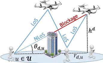
wherea,b are parameters depending on the environment, i.e., number of buildings and large signal obstructions per unit area, building’s height distribution, ratio of built-up area and clean surfaces, etc., as it has been derived in [18], based on the ITU recommendations [33]. In Eq. (1), the ele-vation angle (in radians) appears asθd,u= arctan(hd/rd,u). As θd,u approaches π2, i.e., when the drone d hovers just
above the user u, the probability of LoS reaches its max-imum value. In Figure 2, we see that the positions of the drones directly affect blockage conditions of the ABS–UE acess links. Thus, the higher a drone hovers, the more likely is to have LoS. However, the strength of the signal gets also attenuated with the distance. For single-drone missions, there is an optimal altitude that maximizes coverage [18]. However, in a multi-drone scenario as the one we discuss in this paper, the effects on interference from other drones are a key additional issue to consider, one that makes the op-timal drone hovering altitude depend on the positions and elevations of the rest of the drones. This also precludes the possibility to straightforwardly apply single-drone mission approaches to multi-drone scenarios, since the former are not designed to account for interference, as in [9].
3.2.1 Ground-to-ground channel
Ground cellular links, i.e., gNB–UE access links, operate over an OFMDA channel with access bandwidthWA. Hence, users scheduled by the samegNBdo not suffer intra-cell in-terference. However, ground users may enjoy poor QoS due
Figure 2. Reference illustration of LoS conditions.
to the presence of inter-cell interference, from other close
gNBs. The path-loss of these channels is based on large- and small-scale fading, as widely studied in literature [34] and shown in Table 1. We denote the SINR of ground access links (g, u)asΓAg,uand impose that its minimum user access rate, i.e.,U1
gWAlog2 1+Γ A g,u
, is above the guaranteed rateRAmin.
3.2.2 Ground-to-air channel
In order to provide backhaul connectivity to ABSs, gNBs perform 3D–beamforming over clear LoS links. Hence, the attenuation that a signal fromgNB gtoABS dsuffers is:
LB(g, d) = 10ηBlog10
4πfB cl
· Πg−Π
d
+NσB, (2)
where ηB ≈ 2 is the path-loss exponent in free-space LoS links,fB is the frequency of backhaul wireless links in Hz,
cl is the speed of light in m/s andNσB is a random gaus-sian variable with zero mean and σB standard deviation, modelling the effects of slow fading and shadowing.
3D–beamforming builds antenna patterns that radiate much of the energy over a main lobe with a half-power beam-width (HPBW) that may be wide, hence incurring high interference to otherABSs in LoS. Also, the formation of directional beam-patterns comes with the presence of side-lobes with non-negligible radiating power, that also incur (low) interference. Thus, depending on the radiating angle of other gNBs, a backhaul link may enjoy better or worse QoS, due to the presence of interference3. We denote the backhaul SINR of link(g, d)asΓBg,d, which is equal to:
ΓBg,d=
PT xg ·Gg·10−LB(g,d)/10 Nd+IB
g,d
, (3)
wherePT xg is the transmission power ofg,Ggis the antenna gain over the main lobe of the beam-pattern ofg,Nd is the thermal noise, and most importantly,IB
g,dis the actual inter-ference thatABS dsuffers from any othergNB, depending on the angle of their beam-patterns, i.e.:
Ig,dB =
X
g0∈G\{g}
PT xg0 ·Gg0(φg0,d)·10−LB(g 0,d)/10
, (4)
whereφg0,d is the angle between the direction of the main lobe of the antenna ofg0and the position ofABS d. We im-pose that the minimum backhaul rate,D1gWBlog2 1+ΓBg,d
, is above a rateRBmin.WBis the backhaul channel bandwidth.
3. In general, since beamforming builds antenna patterns with
IEEE TRANSACTIONS ON MOBILE COMPUTING 5
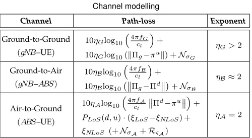
Table 1 Channel modelling
Channel Path-loss Exponent
Ground-to-Ground
(gNB–UE)
10ηGlog10
4πfG cl
+z}|{I
10ηGlog10(kΠg−πuk) +NσG
ηG>2
Ground-to-Air
(gNB–ABS)
10ηBlog10 4πf
B cl
+z}|{I
10ηBlog10 Πg−Πd
+NσB
ηB≈2
Air-to-Ground
(ABS–UE)
10ηAlog10
4πfA cl
Πd−πu
+
z}|{ I
PLoS(d, u)·(ξLoS−ξNLoS) +
ξNLoS (+NσA+RςA)
ηA= 2
3.2.3 Air-to-ground channel
While ground cellular links suffer from conventional atten-uation based on fast and slow fading, the path-loss of an
ABS–UE link(d, u)differs notably and is affected by an ex-cess attenuation, depending on the LoS likelihood presented in Eq. (1). The average attenuation is derived in [18] as:
LA(d, u) = 10ηAlog10
4πfA cl
·q(hd)2+r2
d,u
+ PLoS(d, u)·(ξLoS−ξNLoS) +ξNLoS, (5)
whereξLoS, ξNLoSare theexcess path-losscomponents in LoS and NLoS connections respectively,ηA= 2is the path-loss exponent andfAis the carrier frequency in Hz. As surveyed in [35], we have based the air-to-ground path-loss on the average large-scale fading in order to perform the ABS– UE association in the optimization. Nevertheless, we further consider fast and slow fading, modelled as log-normal and Rayleigh distributions, respectively, in the implementation of the framework when we analyze the results. We denote the access link SINR asΓA
d,u, which is equal to:
ΓAd,u=
PT xd ·10
−LA(d,u)/10
Nu+Id,uA
, (6)
where PT xd is the transmission power of the antenna inte-grated in the ABS d, Nu is the thermal noise, and most importantly,Id,uA is the actual interference that userusuffers from any otherABSs. Thus, the interference depends on the 3–D position of the rest of theABSs, i.e.:
Id,uA =
X
d0∈D\{d} PT xd0 ·10
−LA(d0,u)/10
. (7)
We impose that the minimum rate, U1dWAlog2 1+ΓAd,u
, is aboveRAmin, whereWAis the access channel bandwidth.
In our system model,ABSs operate in orthogonal band-width with the cellular band. Thus, there is no interference between cellular users and drone-served users, which is commonly the main limiting factor in aided cellular net-works, as e.g.,inbandD2D networks [5].
In Table 1 we gather the path-loss model used for each kind of channel, where fG is the band used for gNB–UE access links and is equal to thegNB–ABSbackhaul links, i.e.,
fG=fA, andRςA is a random Rayleigh variable with scale parameter ςA. In Table 2 we summarize the interference suffered in each of the channels, as it has been described along this section. We have shadowed the table cells that imply presence of interference.
Table 2 Channel interference
Ground-to--Ground
Ground--to-Air
Air-to--Ground
Ground-to--Ground
Inter-cell interference
Directional re-use
Orthogonal bands
Ground--to-Air
Directional re-use
Low interference: 3D–beamforming
Orthogonal bands
Air-to--Ground
Orthogonal bands
Orthogonal bands
Inter-drone interference
4
MULTI-DRONE COVERAGE FRAMEWORK
We aim to find optimal 3–D positions for a fleet ofDdrones in which the number of UEs under network coverage is maximum. The optimization is run at regular time intervals, considering every time the users as static, so that static drone positions solve the coverage problem. The coverage maximization provides a set of 3–D coordinates where drones have to fly during the time interval, provided a drone d has to fly towards a reachable destination, i.e., a point within the ballSdof radius given by the drone speed times the duration of the optimization update interval. However, the output of the optimization does not neces-sarily coincide with the assignment of fleet destinations that also minimizes flight time. Hence, we will solve the assign-ment of fleet destinations as a secondary problem, given the optimal coordinates found by the primary problem.
Although it is possible to formulate the coverage max-imization and the minimum flight time assignment in one optimization problem, we believe that it is more clear to decouple both problems and solve them separately, while having the same optimal solution. This is due to the fact that the set of optimal drone positions is not changed by solving the secondary problem and at least one feasible solution exists for the secondary problem, which is the output of the primary problem. Thus, we first present the optimal aerial coverage (Section 4.1) and then the assignment of fleet destinations (Section 4.2).
4.1 Optimal aerial coverage
Coverage ProblemC:Given a fleetDof drone relays in a cellular network managed by a centralized orchestrator,U ground users, a height range [hmin, hmax] for theABSs, guaranteed coverage
ratesRAmin,RBminfor access and backhaul channels respectively, and a maximum number of usersUgandUdthatgNBs andABSs can cover, find the optimal 3–D positionsΠd= (Xd, Yd, hd)of drones so to maximize the amount of users covered by ground-and drone-cells.
Since the positions of drones, including their heights, affect the shape of the covered regions, we can math-ematically formulate the Coverage Problem C to search for optimal values of the continuous decision variables Πd = (Xd, Yd, hd) ∈
R3 that maximize the number of users under network coverage. Denoting byCb,uthe binary variable that takes value 1 if BS b∈ G ∪ A covers user u
IEEE TRANSACTIONS ON MOBILE COMPUTING 6 max
{Πd}d∈D
X
u∈U
X
g∈G Cg,u+
X d∈D Cd,u ! ; subject to:
Access network constraints: 1
UbWAlog2 1 + Γ A b,u
≥RAmin·Cb,u, ∀b∈ G ∪D,∀u∈ U;
P
g∈G
Cg,u+ P d∈D
Cd,u≤1, ∀u∈ U;
P
u∈U
Cg,u≤Ug; P u∈U
Cd,u≤Ud, ∀g∈ G,∀d∈ D;
Backhaul network constraints: 1
DgWBlog2 1 + Γ
B g,d
≥RBmin·Bg,d, ∀g∈ G,∀d∈ D;
P
g∈G
Bg,d≤1, ∀d∈ D;
P
d∈D
Bg,d≤Dg, ∀g∈ G;
Access–backhaul constraints:
Cd,u≤ P g∈G
Bg,d, ∀d∈ D,∀u∈ U;
P
d∈D
P
u∈U
Bg,d·Cd,u≤Ug; ∀g∈ G;
Drone air-space constraint:
Πd∈ Sd, ∀d∈ D.
(8)
Access network constraints: The first constraint guaran-tees that the access link rate between BS b and user u is above RminA as soon as u accesses the network via b; the second constraint tells that a user cannot be covered by more than 1 BS; the third constraint accounts for the number of users that each BS (eithergNBorABS) can serve.
Backhaul network constraints:The forth constraint guar-antees that the backhaul link rate betweengNB gandABS d
is aboveRB
minas soon asdconnects to the network viag; the
fifth constraint tells that each ABS cannot connect to more than 1gNB; the sixth constraint limits the number of drones that eachgNB gcan serve to a maximum ofDgdrones.
Access–backhaul constraints: The seventh constraint states that a userucan connect to a dronedonly ifdis under the coverage of somegNB. Hence, each drone that provides network access to at least one ground user is connected to the network via one backhaul link, so that, every ground user served by a drone is indeed attached to the cellular network. The eighth constraint states that the number of users covered by those drones attached to the samegNB g
is limited by the maximum capacity of usersUging. Drone air-space constraint: Finally, the air location of a dronedhas to be within a 3–D regionSd⊆ S ×[hmin, hmax]
which can be reached in the time interval used for optimiza-tion, depending on flight speed and current drone position. Feasibility. The optimization problem in Eq. (8) is al-ways feasible. For instance, consider a general instance of the problem. Take a random position for eachABS dinside their reachable regions Sd. Now set all binary variables {Cb,u}, {Bg,d} equal to 0. Since the SINR functions ΓBg,d, ΓAb,u are always positive (see Eqs. (3), (6), respectively), the solution satisfies all the constraints. This solution provides a utility function of0users covered, but it is feasible.
Complexity. Problem C is NP-Complete because, as shown in Appendix A, the well-known NP-Complete min-imum geometric disk cover(MGDC) problem [36] can be re-duced, in polynomial time, to a particular case of ProblemC. The first constraint on the user access rate, whenb∈ D, is non-linear and very complex (also the forth constraint), since it depends on the air-to-ground path-loss shown in
Eq. (5) for one link, but also for the interfering links from other drones. To make the constraint more visual and remark its non-linearity and complexity, we develop its expression for a dronedas follows:
K1 (hd)2+r2
d,u
·10K2PLoS(hd,rd,u)
Nu+ P d0∈D\{d}
K1 (hd0)2+r2
d0,u
·10K2PLoS(hd0,rd0,u)
≥(2K3−1)·C
d,u, (9)
where the continuous variablerd,u=k(xu, yu)−(Xd, Yd)k is the distance between useruand the ground projection of droned, and K1=PT xd ·
cl
4πfc
2
·10ξNLoS10 ,K2=ξNLoS−ξLoS 10
and K3 =
Ud·RAmin
WA are constant. In Eq. (9) we see that this constraint depends on the position decision variables (Xd, Yd, hd)not only as an attenuation from the distance, but they also affect the LoS probability, as shown in Eq. (1). Unlike previous works like [3], [9], [37], in which the drone-service condition is basedonlyon the attenuation or the Signal-to-Noise Ratio (SNR), in (8) we have formulated a novel 3–D drone placement optimization that accounts for the actual inter-drone interference suffered by ground users. Eq (8) represents a Mixed-Integer Non-Convex Program (MINCP), which is not tractable with currently available optimizers dealing with problems that are, at least, convex. Since problem (8) presents a non-convex formulation mainly because of the attenuation depending on the LoS probability, we cannot apply any off-the-shelf optimizer to optimally solve this problem. In addition, the problem itself is NP-Complete, so we resort to a heuristic, as detailed in Section 5.
4.2 Assignment of fleet destinations
The second problem to solve when users move and drones have to be repositioned is an assignment problem. Since it does not matter which ABS goes to which destination (as long as such destination is reachable), we enforce each drone to fly towards the positions that minimize the aggregated flight-time by the fleet. Formally, we dispose of a fleet ofD
drones that must fly from source positions {πd}
d∈D and reach target positions {Πd0}D
d0=1. Thus, we formulate the followingassignment problem:
min Fd,d0
Ufly=
X
d∈D D
X
d0=1
Tπd,Πd0·Fd,d0;
subject to: D
P
d0=1
Fd,d0 = 1, ∀d∈ D;
P
d∈D
Fd,d0 = 1, ∀1≤d0≤D;
Fd,d0 ∈ {0,1}, ∀d∈ D;
∀1≤d0≤D,
(10)
where we have introduced the binary variableFd,d0 ∈ {0,1} to denote whether drone d flies from πd to Πd0 or not. Tπd,Πd0is the assignment weight, and depends on the time that dronedneeds to fly from source positionπdto the destination Πd0. The equality constraints ensure that each destination Πd0 is reached by only one drone d, and that each dronedreaches only one destinationΠd0. The utility
Uflyis used to minimize the flight time of the fleet of drones. For simplicity, we assume that dronesdfly at a constant speeds ofvd. Thus, the time needed to fly fromπdtoΠd
0 is:
T∗πd,Πd0=
π
d
−Πd0
.
IEEE TRANSACTIONS ON MOBILE COMPUTING 7
However, each drone d can reach only those destinations with coordinates within their reachable region Sd. Hence, we impose infinite required time for each dronedto reach all destinationsΠd0that fall outsideSd:
Tπd,Πd0=
(
T∗
πd,Πd0
, ifΠd0∈ Sd;
+∞, ifΠd0∈ S/ d.
(12)
Hence, the optimization in Eq. (10) assigns to each droned
one destinationΠd0
such thatdis able to reachΠd0
and the aggregated flight time is minimized.
Feasibility. The optimization problem presented in Eq. (10) is always feasible and finite. For instance, assigning to each dronedthe destinationΠd= (Xd, Yd, hd)obtained as an output of the optimization problem of Eq. (8) provides a (finite) feasible solution.
Complexity. The optimization problem in Eq. (10) is a special case of mixed-integer linear program (MILP), one that can be solved efficiently in polynomial time through the Hungarian method[38], with complexity O(D3). Therefore, this second problem related to dynamic networks is easy to address optimally in low-degree polynomial time.
5
DYNAMIC DRONE REPOSITIONING ALGORITHMS
So far we have discussed the optimization of the placement of a fleet ofABSs hovering over a ground cellular network (see Section 4.1), and the optimal flight assignment that minimizes the flight time (see Section 4.2), thus overlaying a legacy cellular network managed by an orchestrator. Nev-ertheless, since users move, the optimization is reconsid-ered periodically, with updated drone air-space constraints. Repositioning has to be run frequently, so that we need efficient heuristics. Next, we describe how to practically implement the optimization framework described so far.
5.1 OnDrone: an algorithm suit for on-demand drone coverage optimization
Coverage Problem C is NP-Complete, thus optima cannot be reliably solved on-demand for fast placement of drones, which is key for dynamic repositioning cases. Thus, even if the problem was optimally solvable, the need of having an efficient heuristic would remain. To this aim, we propose here an On-demand Drone Coverage (OnDrone) algorithm, based on anextremal-optimizationalgorithm (EOA) that runs in polynomial time. For benchmarking purposes, we further consider state-of-the-art proposals from [9] and [10].
5.1.1 OnDronefor multi-drone coverage
EOAs are evolutionary algorithms that restrict the search space and achieve near-optimal results in polynomial time [7]. EOAs are based on a fitness metric and, at each step, try to improve the configuration of the element of the system that yields the least contribution to the fitness metric. Therefore, EOA’s principles perfectly match the na-ture of the coverage problem addressed. Specifically, the fitness function is the number of covered users and the least significant contribution comes from the drone that covers the least number of users. Such drone may be either far from users, where its transmissions are severely affected by the interference coming from the rest ofABSs, or in a position
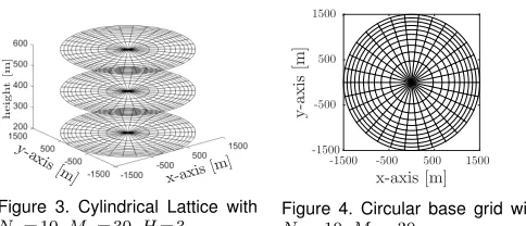
Figure 3. Cylindrical Lattice with Nρ= 10,Mθ= 30,H= 3.
x-axis [m] -1500 -500 500 1500
y
-a
x
is
[m
]
-1500 -500 500 1500
Figure 4. Circular base grid with Nρ= 10,Mθ= 30.
where the backhaul service is low. Thus, it is convenient to reposition such drone and increase the coverage.
The search space for drone locations is restricted to a lattice, as shown in Figure 3. We derive a cylindrical lattice that contains the ground network surface S composed by the positions over whichOnDronemoves theABSs to get the best coverage utility. Those lattice points that fall outside the ground region S are discarded, so the design of the lattice applies to any shape ofS. We split the base into a grid of equal areas (see Figure 4), and the height into equidistant altitudes. This leads to a cylindrical lattice of equal volume subspaces. Specifically, we divide the square of the radius and the angle of the base grid inNρ andMθ equal pieces. In polar coordinates, the resulting points and base grid are:
ρi =
p
i/Nρ·RC, i= 1, ..., Nρ; θj = 2π·(j−1)/Mθ, j= 1, ..., Mθ;
G = {(ρi, θj)∈D(0, RC) | 1≤i≤Nρ,1≤j≤Mθ},
where D(0, RC) is the closed disk in R2 centered at the origin and of radiusRC (whereRCis big enough to make
D(0, RC)containS). In this way, the base area is divided into Nρ×Mθ regions with the same area A = Ai =
π Mθ(ρ
2
i+1−ρ2i) = πR2C
NρMθ, fori = 1, ..., Nρ−1, which does not depend oni(see Figure 4). The height of the cylinder is divided intoHequidistant segments in the interval between minimum and maximum drone hovering height,hmin and hmax. In cylindrical coordinates, the resulting lattice is
L={(ρ, θ, hk)∈G×R | 1≤k≤H}. (13)
The proposed EOA—OnDrone—begins with an initial feasible and suboptimal (random) implementation of the system. Then, it updates the positions of theABSs providing worst individual contribution to the full performance, i.e., the drone covering less users. At each iteration, the “least fit”ABSis selected andmovedto a reachable position where the system utility increases as much as possible, considering the coverage by ground- and drone-cells. Also, OnDrone provides a new position where the drone can be attached to agNB that provides backhaul service with the guaranteed QoS. To decrease the probability of finding only local op-tima, we consider that if the worst performing drone cannot be moved to improve coverage, then we try to reposition the next worst-performing drone.OnDrone keeps moving the ABSs with lowest contribution until it does not find any better location for anyABS, or it reaches a maximum number of iterationsi0∈N. The optimality of this algorithm
is studied in Section 6.
IEEE TRANSACTIONS ON MOBILE COMPUTING 8
Algorithm 1OnDrone: On-demand Drone Coverage for 3-D Drone Placement
Require: LatticeL, BSsG ∪D, usersU, Signal parameters.
1: Randomly place alldatΠd ∈ L
. DefineΠ ={Πd}d∈D .
2: Compute number Ud0(Π) of UEs covered by all g∈ G andd∈ D If D1
gWBlog2 1+Γ B g,d
< RminB ,∀g∈ G, then
Ud0(Π) = 0
.
3: Selectd0= arg mind∈D{U 0 d(Π)}.
4: TakeΠd0= arg maxπ∈L{]of UEs covered ifd
0is atπ |
∃g∈ G: D1
gWBlog2 1+Γ B g,d0
≥RBmininπ}.
5: If the same coverage remains when placing d0 atΠd0,
go back to step 3 ignoring unsuccessfuld0’s. 6: Placed0atΠd0and setΠ← {Πd}d∈D.
7: Go back to step 2 until:
• Ground-plus-air coverage is no longer improved. • Maximum number of iterationsi0is reached.
d0 ∈ D is selected and repositioned. Such droned0 selects
the 3–D positionΠd0 in the latticeL(see Eq. (13)) at which gNBs and ABSs cover more users as long as there exists
g ∈ G providing the guaranteed backhaul QoS in that position. A useruis covered by anABS donly if the user rate experienced is greater than minimal user access rate
RAmin and dis covering at most Ud users, so that uenjoys the guaranteed QoS. Thus, the signal strength fromd0 and
from the rest of the drones inD\{d0}must be checked. This
means that the complexity of each iteration isO(|L| ·D·U), whereL is the size of the lattice. Sincei0 is the maximum
number of iterations needed for the algorithm to converge to a solution, the complexity ofOnDroneisO(i0·|L|·D·U),
wherei0is constant and can be omitted.
We remark that, unlike the NP-Complete problem pre-sented in the previous section,OnDronerequires few itera-tions. Indeed, we have performed all the experiments in this paper in few seconds in a personal computer, on average. As a matter of fact,OnDroneis intended to be used in an on-demand fashion, dynamically repositioning drones to adapt to user’s moves over time. OnDroneis then practical and can be executed at the network orchestrator.
5.1.2 Seq: Sequential Multi-Placement
In addition to OnDrone, we have also developed a sim-ple heuristic that finds feasible solutions to the Coverage Problem C in polynomial time. We base this algorithm on the Efficient 3-D Placement—hence the name of the algorithm—scheme derived in [9], and thus we adapt it toSequential Multi-Placement (Seq)in order to support aerial networks with more than one ABS. In [9], the authors model the presence of one drone providing coverage in one single cell, i.e., they maximize coverage for single drone missions. They model a circular drone footprint, which allows to formulate a convex optimization problem due to the presence ofonly one drone. We adapt the proposal in [9] to place ABSs one by one, according to realistic interference metricsnot originally considered in that work.Seqwill be used as a benchmark forOnDrone.
We build the Seq heuristic by induction as follows: Since the framework proposed in [9] only considers drone-coverage, we first compute the amount of users covered
by ground-cells. Second, we select one ABS and maxi-mize coverage as described in [9] (i.e., using Efficient 3-D Placement) for the remaining non-covered users, namelyU0. Here, the placement space for drones is restricted to those positions where at least onegNBprovides backhaul connectivity with the guaranteed QoS. We denote asU1 to
the set of users that are covered by the first selectedABS. For this firstABS, there are no interference issues.
Let i >1 and assume that we have locatedi−1 ABSs
and that we want to locate thei-thABS. Assume thatUik are the sets of UEs that each previous ik-th ABS covers at the moment of its placement. Then, Seq finds a 3–D position at which the i-th ABS covers more users from the setU0\S
1≤ik<iUik and at least one gNBprovides the requested backhaul QoS. Thus, thei-thABS aims to cover the maximum number of users that are not covered yet.
Seq ends when the D-th ABS is located. After this, the algorithm computes the actual number of users served according to interference (in both the backhaul and access network). Hence,Seqhas the same objective as OnDrone: covering the maximum number of users according to QoS guarantees. We report the pseudocode in Algorithm 2.
At each iteration i > 1, the i-th ABS sequentially se-lects the best position for it based on Efficient 3-D Placement from [9] maximizing its own coverage, no matter how its position affects the coverage of the remaining
ABSs or the already set backhaul links. Since placing the newi-thABSadds interference to the system, the previous
i−1 drone-cells shrink, and cover less UEs than the ones originally intended by theSeqchoice.
Complexity. The complexity of Seq is evaluated as follows. Seqmakes D steps, one per each drone. At each stepd,Seqdefines the final position of droned∈ D. In [9], the authors do not propose any algorithm for placing the drone, but they solve a convex mixed-integer non-linear program with a convex optimizer. Such optimizer does not run an algorithm with polynomial-time complexity. Instead, it performs a combination of interior-point methods with a branch&bound search [39]. Hence, we opt for approxi-mating their problem through a search on the latticeL. As in OnDrone, checking whether a user is covered requires to check the signal strength of the serving drone along with the interfering drones, i.e., D signal strengths. The complexity of this process is O(|L| ·D·U). After the last
Algorithm 2Seq: Sequential Multi-Placement
Require: BSsG ∪D, usersU, and Signal parameters.
1: Compute the number of users covered by ground-cells.
2: FindΠd1 ∈R3whered
1covers more users fromU
0 and ∃g∈ G | 1
DgWBlog2 1+Γ B g,d1
≥RBmin.
3: Define the set of users covered byd1:U1⊆ U
0 .
4: for2≤i≤D
5: FindΠdi∈R3whered
icovers more UEs inU 0
\ S 1≤ik<i
Uik
such that∃g∈ G | 1
DgWBlog2 1+Γ B g,di
≥RBmininΠdi.
6: Define the set of UEs served bydi:Ui⊆ U 0
\ S 1≤ik<i
Uik.
7: end for
IEEE TRANSACTIONS ON MOBILE COMPUTING 9
iteration, the algorithm checks which users are actually covered, since those users that at some iteration i were covered, may no longer enjoy the guaranteed QoS because of the repositioning of other drones in successive iterations. This check has a complexity of O(D2·U). Thus, the com-plexity of theSequential Multi-Placementalgorithm is O(|L| ·D·U +D2·U), that is similar to the complexity
ofOnDrone because|L| ≥ D, since drones cannot be co-located and so the number of possible distinct drone posi-tions cannot be smaller than the number of drones (indeed, in a well designed system,|L| D).
5.1.3 RA: aRepulsion-Attractionscheme
Here we briefly describe the Repulsion-Attraction (RA) scheme derived in [10].RAis a multi-drone placement scheme in which several self-organized ABSs dynamically change their position to track clusters of users. The approach is based on the assumption thatABSs will be attracted by the presence of users in the ground, and will be repulsed by
gNBs and otherABSs in order to avoid interference. Complexity. RAconsists into maximizing a non-integer metric without any constraints. Hence, one can apply stan-dard methods like line-search or trust-regions methods for unconstrained optimization. Such methods have low complexity and their performance depends on the tar-get tolerance on the error. Moreover they converge really quickly [39], with a linear dependance on the number of iterationsiRA, i.e., the complexity isO(iRA).
5.2 B ´ezier flight routes
The last problem to solve consists in designing drone’s trajectories. The output of OnDrone(Section 5.1), and the Hungarian method (Section 4.2), provide the source and destination for each drone carrying anABS. Therefore, we now design a route optimization scheme.
While drones fly, both the backhaul and users association change. Initially, each ABS attaches to a gNB with the required QoS and starts the flight. Once the backhaul QoS level is low due to long distance or interference impairment, the ABS sets a backhaul link with a new gNB with the guaranteed QoS. Similarly, while a drone flies, UEs attach to thatABS in case that the minimum access data link rate (i.e., QoS) is guaranteed. Upon arrival to the destination, the association is already optimal in terms of coverage.
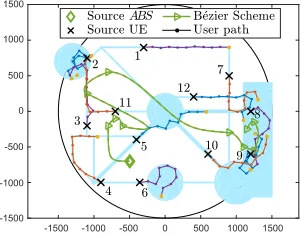
On the one hand, drones have high aerial mobility and fly over a ground cellular network in a 3–D space, without many restrictions of walls, streets or vehicles. On the other hand, drones hovering over regions with good QoS from somegNBs or under-populated regions with a big surface may lead to under-utilizedABSs and low coverage, depend-ing on the topology of users. Furthermore, if a drone is not fast enough, it might occur that when the drone arrives at the destination the users topology has changed too much so the destination is no longer optimal, and the network needs to be re-optimized. To avoid such undesired effects, and knowing that drones may have to be redirected while flying towards a destination, we propose drone paths following B´ezier curves [8], instead of commonly assumed straight lines, as adopted in [11]. Indeed, usingB´ezier curvesallows to deflect drone trajectories towards areas with higher user
Algorithm 3B´ezier Scheme
Require: P0={πd,Πd},ω,B,τ = (1 +α)·λ βP0(t)
.
1: UP0=U ∩ Sω βP0(t).
2: k= 0.
3: while|Pk|< B & λ βPk(t)< τ,do:
4: for u ∈ UPk, gPk
u = |{u0 ∈ UPk | ku0−uk ≤
ω/2}|/ πω2/4
.
5: uk+1= arg maxu∈UPk
n gPk
u | λ
βPk∪{u}(t)
≤τ o
.
6: Pk+1 =Pk∪{uk+1}, UPk+1=UPk∩Sω βPk+1(t)
.
7: k=k+ 1.
8: end while
9: P =Pk−1.
density, so to enhance drone coverage and enable unique coverage opportunitieswhiledrones seek their optimal po-sition. Since we leverage on the notion of B´ezier curve, Appendix B provides some background on the subject.
In our proposal, we define the set of anchor points for ourB´ezier-based flight path and use the standardde Castel-jau algorithm [8] to derive theB´ezier curvecorresponding to the selected anchor points (see Appendix B for details).
We obtain the set of anchor points inductively, as de-tailed next. Let πd and Πd be source and destination of a droned∈ D, letω >0be the width for the two-sided offset region of the curves and letB >1be the maximum number of anchor points for the B´ezier curve. B is determined as the density of users covered per drone-cell, since in case a drone cannot cover more than B users, it does not make sense that such drone wishes to deflect its path attracted by more thanB users. We take ω = 2Rd, whereRd is the maximum range at which dronedcan provide coverage in its optimal position. We define as the initial set of anchor pointsP0both nodes:P0 ={πd,Πd}. Thus, we define the
B´ezier curve βP0(t) for P
0, which is the segment joining πd
and Πd
, computed with the de Casteljau algorithm [8]. Now, we iteratively modify the currentB´ezier curveuntil we derive the finalB´ezierpath. Given a curveβ(t), we denote its length as λ(β(t)), and take λ βP0(t) as a reference
length for the finalB´ezier curve. Indeed, we build aB´ezier Scheme such that the obtained curve is not longer than
τ = (1+α)·λ βP0(t), for a givenα >0.αis determined
as the fraction of the time interval in which a drone would have already arrived to its destination in case of following a straight path. Hence, we make sure that a drone reaches its destination but has the flexibility to deflect its path to improve coverage. Let Sω(β(t))
be the two-sided offset region of widthω that results from stroking a curveβ(t), and letUP0 =Sω βP0(t)∩ U be the set of users that are
inside the offset region of βP0(t). We denote by gP0
u the gravity of a user u∈ UP0 and define it as the density of
users in a disk centered inuwith radiusω/2:
gP0
u =
{u
0
∈ UP0 | ku−u0k ≤ω/2} .
πω2/4
. (14)
The first user u1 selected as anchor point is the one with
highest gravity inUP0 such that the resultingB´ezier curve
is not longer thanτ= (1+α)·λ βP0(t), i.e.:
u1= arg max
u∈UP0 n
gP0
u | λ
βP0∪{u}(t)≤τo. (15)
Now,P1=P0∪{u1}defines a newB´ezier curve,βP1(t).
IEEE TRANSACTIONS ON MOBILE COMPUTING 10
Table 3
Summary of Algorithms’ Complexity
Algorithm Complexity
Optimal Aerial Coverage (Section 4.1) NP-Complete
Assignment of Fleet Destinations
(Section 4.2) O(D
3)
OnDrone(Section 5.1.1) O(|L|·D·U)
Seq(Section 5.1.2) O(|L|·D·U+D2·U)
RA(Section 5.1.3) O(iRA)
B´ezier Scheme(Section 5.2) O(B3)
Overall Optimization Framework
withOnDrone(Section 5.3) O(|L|·D·U) +O(D
3)
each order defines a different curve. Thus, we sort the points in increasing order according to the distance to the source,πd. Finally,UP1=UP0∩ Sω βP1(t)is the updated
set of users for next iteration. Then, we keep selecting anchor points for the B´ezier curve while they exist, until the length of the B´ezier curveexceeds τ or the maximum numberB of anchor points is reached. At each iterationk, we build a new curve fromPk−1,UPk−1 andβPk−1(t).
Complexity. We show the derived B´ezier Scheme in Algorithm 3. Its complexity can be evaluated as follows. There is an iteration of thede Casteljaualgorithm to derive eachB´ezier curveβPk(t). The complexity of thede Casteljau algorithm is quadratic with the number of anchor points of the B´ezier curve that it builds [8]. The B´ezier Scheme runs at most B iterations, and at each iteration k it uses
k+2 =|Pk| ≤Banchor points. Thus, the complexity of the B´ezier Scheme isO(B3), whereBis the maximum number of anchor points allowed.
5.3 Overall complexity
In Figure 5 we show the flow chart of the proposed optimization framework for drone-aided dynamic cellular networks. As we have fully detailed in the paper, first we solve, through OnDrone, the framework for maximizing network coverage in polynomial time. OnDrone outputs the optimal 3–D positions at which drones must locate, given their previous positions. However, drones do not move instantaneously. The Hungarian method solves then the assignment problem that minimizes the distance flown in polynomial time, and outputs the source and destina-tion of each drone concretely. Finally, our B´ezier Scheme designs the flight routes of drones in order to deflect their paths towards clusters of users and increase the coverage efficiency over the time interval. This is another polynomial time algorithm. Therefore, the overall optimization frame-work runs in polynomial time. The overall complexity of our framework for fast repositioning of drone-aided cells is the result of summing the complexities of the schemes that compose such framework, which is shown in Figure 5. When the 3–D placement optimization is performed by OnDrone, the complexity isO(|L|·D·U)+O(D3)+O(B3) =
O(|L| ·D·U) +O(B3)
, since|L| U D.
In Table 3 we summarize the complexities of the detailed algorithms, including theoverall optimization framework.
5.4 Orchestration of the optimization framework
The possibility to integrate the above described framework into a communication system raises several alternatives
Figure 5. Flow chart of the drone-aided dynamic network.
regarding where the different algorithms can be executed. First, there is the issue of deciding where the drones must be located at each time instant. This task (i.e., to execute OnDrone for drone placement) should be assigned to a device on which all drones have direct communication and therefore can easily know what must be their destination. Therefore, thegNBs seem to be an appropriate place for the orchestration of drones’ positions. In alternative, and con-sidering current trends in 5G networks architecture design, the orchestrator can be a software slice in the MEC, which is the edge-cloud computing platform of future 5G cellular networks and which resides just next to base stations [40].
The second issue consists in designing drone’s trajecto-ries, provided it must change its current location. However, the B´ezier curves used for the flight routes have been al-ready designed in a discretized manner with thede Casteljau algorithm, using short straight segments to build a B´ezier curve. At this point, we note that currently, most drones are already capable of autonomously travel to concrete positions following straight lines (see for instance [41]). So, drones can follow such short segments (using their originally integrated traveling mechanisms) without sig-nificantly deviating from the flight route provided by the B´ezier scheme. In that case, those responsible for such tasks (i.e., obtain the discretized B´ezier curves and follow the corresponding straight segments) are the drones themselves.
6
EXPERIMENTAL RESULTS
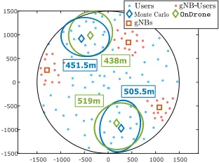
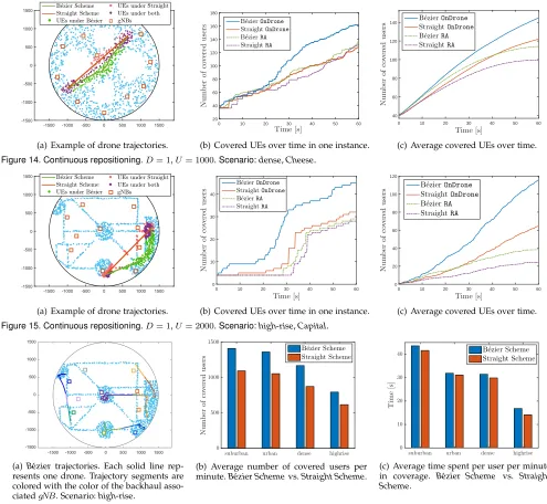
Here we numerically assess the performance of our multi-drone optimization framework. We assess the coverage offered by the network, with the assistance of a fleet of drones, in a circular surface. We compare optimal placement results yielded byOnDrone(presented in Section 5.1.1) with the ones obtained with Seq (based on [9] and described in Section 5.1.2) and with the RA scheme (from [10], and described in Section 5.1.3). We also compare the results with the optimal achieved by means of Monte Carlo sim-ulations, since computing exact optima is not doable in networks with as few as a fistful of UEs,gNBs, and drones. Besides, we compare our scheme to a modified OnDrone that neglects interference (referred as “iNeg” in the figures). Hence, we assess the importance of introducing interference in the analysis. We also compare coverage results while drones reposition following the B´ezier Scheme (presented in Section 5.2) with a simplerStraight Scheme, as adopted in [11], which consists in moving drones over straight paths towards a certain destination identified with theHungarian method(see Section 4.2). SinceRAhas been designed in [10] to dynamically track UEs, we compare also theB´ezierand Straight Schemeswhen the path planning is based onRA.
IEEE TRANSACTIONS ON MOBILE COMPUTING 11
Table 4
Environmental parameters for the computation of LoS probability
Environment suburban urban dense high-rise
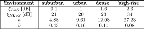
ξLoS[dB] 0.1 1 1.6 2.3 ξNLoS[dB] 21 20 23 34 a 4.88 9.61 12.08 27.23 b 0.43 0.16 0.11 0.08
denseandhigh-rise. These four environments correspond to different densities of elements (e.g., buildings) that affect the LoS probability. Moreover we study three distinct cases of deployment scenarios, in which the location of users follows different distributions:
• PPP: We place UEs in a circular surface, according to a Poisson point process.
• Cheese: We define a surface that includes certain regions which are not accessible to UEs, and locate UEs uniformly random in the rest of the network. Then, we have a surface with empty areas (like in a Swiss cheese). This users’ distribution is typical of public gardens or areas with restricted zones. • Capital: We also run our numerical evaluation over
a simplified map of the center of a dense capital city, Madrid, considering main zones of people affluence and no users in indoor installations.
In the PPP and Cheese scenarios, we locate gNBs ac-cording to the same distribution. Heterogeneous synthetic distributions would be of interest for traffic demand-based optimizations [42], which is out of the scope of this paper, and we therefore do not consider them. However, in the Capital scenario, we consider the actual locations of those
gNBs that belong to the main network operator in the city. In all experiments, the number of iterations required by OnDronewas very small (see Appendix C.1).
Table 4 gathers the parameters for the air-to-ground path-loss model and the probability of LoS described in Eqs. (1) and (5), depending on the density of the environ-ment that we consider in the numerical simulations. These parameters are obtained based on the number of buildings and large signal obstructions per unit area, building’s height distribution, ratio of built-up area and clean surfaces, etc., as it has been derived in [18], based on the ITU recommenda-tions [33]. Such parameters allow to differentiate the main four environmental conditions.
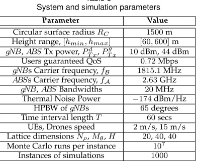
Table 5 gathers the parameters that, unless otherwise specified, we have used for the network model, regardless of the simulation environment. We take a circular surface ofRC= 1.5km of radius where there are 10gNBs, and a height range between hmin= 60m and hmax= 600 m for
drones. This is a generally doable height range,4since lower values would be too close to ground (and, e.g., vehicles or even people) and higher elevation would be affected by high-speed winds which are unsafe for an aerial network of simple drones. However, in our numerical evaluation the actual maximum drone altitude is rather determined by the environment density. For instance, in ahigh-rise envi-ronment, although high altitudes increase the probability
4. Such under-kilometer altitudes comply with current possibilities of commercial drones. For instance, DJI Phantom 4 has an elevation range of few thousands of meters, according to its commercial specifications.
of LoS, the attenuation is much stronger, so that drones need to fly closer to the ground. In contrast, thesuburban orurbanenvironments do not suffer strong attenuation, so that drones can fly higher. However, a high altitude turns into links with higher LoS probability, thus yielding more interference for far ground users.
The power transmission from ABSs is 10 dBm, as adopted in [43], [44], [45], which is notably lower than the usual 44 dBm used for gNBs in the ground network (as we adopt). This is because ABSs have much higher LoS probability than ground base stations and do not use om-nidirectional antennas, and hence require much less power. Using higher ABS transmission power, as 25 or 44 dBm, may provide better coverage due to better signal strength, although also provides less resilience to interference im-pairment, as we discuss in our results. Moreover, ABSs are carried by flying drones, which spend most of their energy into hovering, flying towards desired positions at a given speed, and carrying the weight of the communication equipment. This poses serious constraints on transmission power, as evaluated in [43]. Hence, we have chosen to use a 10dBm of power transmission for analyzing our framework and algorithms. The guaranteed user data rate is0.72Mbps, which guarantees video streaming with 240p resolution [46], and allows 360p and 480p resolution in many cases over the MPEG-4 standard. It also allows adequate videoconferenc-ing quality usvideoconferenc-ing video compression [47]. Such guaranteed rate, with customary20MHz bands and assuming that no more than 100 users can attach to a BS, corresponds to guaranteeing that the SINR is higher thanγA= 10.9dB, ac-cording to the Shannon capacity formula (see Appendix C.2 for a discussion on the minimum data rate experienced under coverage). Besides, such SINR value allows for a 16QAM modulation and a coding rate of1/2 in LTE com-munications, as derived in [48], although we also study the impact of using other guaranteed rates. The carrier fre-quency used bygNBs (either for backhaul channels between
gNBs andABSs or access channels betweengNBs and UEs) and for the access channel between ABSs and users are 1815.1 MHz and 2630 MHz, respectively. These channel parameters are as in the LTE/LTE-A network provided by Movistar in Madrid. As it has been discussed in [31], the antenna patterns ofgNBs for backhaul connectivity are di-rectional with a HPBW of65degrees, according to the 3GPP technical specifications [49]. For dynamic experiments, we slot time into intervals of length T = 60 s. This means that every minute, we re-optimize the network by means ofOnDrone(or with any of the benchmark schemes, asSeq orRAschemes) and immediately re-direct drone flights for dynamic repositioning using the solution of our assignment problem and a flight route computed with either theB´ezier or the basicStraight Schemefrom [11]. Users move accord-ing to the random way-point model (RWP)5(see [50], [51]) with an average speed of2m/s. We update user’s positions every second, while drones fly at a constant speed of15m/s over a continuous path. Moreover, such flight speed allows for low drone energy consumption, according to the energy consumption model for aerial aircrafts derived in [43].