Designing Simple Indoor Navigation System for UAVs
Mohamed Kara Mohamed, Sourav Patra and Alexander Lanzon
Abstract— The wide range of applications and configurations of UAVs raises the need for different types of navigation methodologies compared to the conventional INS/GPS system. For instance, the limitation in cost, size and weight of indoor UAVs makes conventional navigation system unsuitable for these vehicles. In addition, the INS/GPS navigation system is impractical for indoor applications because the GPS signal is not reliable in closed territories. This paper proposes a new, cost-effective and simple indoor navigation system using three laser beams fixed to the body of the UAV and shooting to the ground. Then, a camera and computer vision algorithm are used to capture the laser dots on the ground and determine their coordinates. The position of laser dots is used to obtain full information about the position and orientation of the UAV. The proposed navigation system can be classified as a vision based navigation system, yet, it does not depend highly on the quality of the video shots taken from the vision camera and does not require a heavy image processing algorithm. An illustrative simulation study is conducted to demonstrate the validity of the proposed navigation system.
I. INTRODUCTION ANDRELATEDWORKS
Research interest in Unmanned Aerial Vehicles (UAVs) has grown rapidly due to their wide range of applications [1]. Nevertheless, seeking full autonomy is one of the main factors behind the milestone developments in UAV systems [2], [3]. To achieve autonomy, the UAV needs a navigation system that gives information regarding the status of the vehicle and feeds this information to the controller for an ap-propriate action to be taken. The common navigation system used for large scale UAVs is the Inertial Navigation System coupled with the Global Positioning System (INS/GPS). However, for small UAVs or indoor applications, there is a need for alternative navigation strategies [3]. This is due to the fact that INS/GPS system is relatively expensive and needs a good access to the GPS signal which is not available in case of indoor areas.
The challenge of simple, less costy and efficient indoor navigation schemes has been undertaken by many UAV research groups [1], [3], [4]. Different techniques such as pressure sensors for altitude, magneto-resistive magnetome-ter, laser range finder, radar and ultra sound for position estimation and obstacles detection have been investigated [5], [3], [4]. In this regard, employing vision-based systems
The financial support of Aleppo University (Syria), the Engineering and Physical Sciences Research Council (UK) and the Royal Society (UK) is gratefully acknowledged.
The authors are with the Control Systems Centre, EEE, The University of Manchester, UK, Ph:+44 161 306 8722, Fax:+44-161-306-8729, E-mail addresses:
[email protected] [email protected]
(computer vision systems) for autonomous navigation has attained considerable interest [4] due to the fact that vision based systems are lightweight, passive and produce rich information about the motion of the vehicle [5]. The vision based navigation algorithms were used initially for ground mobile robots and then imported to UAV systems [6]. To use vision based navigation systems, the path of the UAV needs to be known a priori. Images of the surrounding environment of the UAV’s flying path are taken and analyzed to identify the basic features of this path before the flying mission commences. Then, the real time images taken from on-board camera(s) during the flight mission are compared with the visual memory of the vehicle to identify the known features and estimate the motion of the UAV. Different algorithms and schemes are developed to excel the feature detection and speed up the matching process [7], [8].
The computer vision systems might be used solely to esti-mate the motion and orientation of the vehicle by tracking the movement of the captured features in two consecutive shots from the on-board camera [6]. This method is complicated, involves heavy computational burden, affected highly by the quality of the image and the number of features to be ana-lyzed, and works efficiently only in specific territories with good images. To reduce the complexity and computational costs, the image analysis is chosen in [9] to be performed on a ground station where the data is communicated from/to the UAV via a wireless link. This type of implementation reduces the autonomy of the UAV and puts the vehicle at risk in case of wireless communication failure. The vision-based information is integrated with other sensors such as GPS/gyroscope in [10] to refine and correct the estimation of the UAV’s motion. This again requires a good GPS signal and is impractical for indoor applications or urban territories. To sum up, computer vision based systems are still developing and have many software and hardware difficulties.
A laser based navigation scheme is developed in [11] where the projection of four diode spots on the ground is used to estimate the dimensional position of the helicopter. However, the estimation of the motion of the helicopter is made by the maximum likelihood method. The algo-rithm contains over-determined nonlinear equations, and the authors have not discussed how to solve these equations. Moreover, the navigation system performance was not con-sidered and rather the focus was on the control system of the helicopter.
but in the same time is cost-effective and easy to implement. The proposed navigation strategy uses the locations of three laser dots generated by the three laser beams fixed to the body of the vehicle to identify the status of the UAV without further requirement for optimization algorithm, fusing data estimation method like Extended Kalman Filter or additional GPS/IMU sensors. To capture the laser dots on the ground and analyze their coordinates, a computer vision technique is used, e.g., the Scale Invariant Feature Transform (SIFT) algorithm developed in [12]. The computer vision algorithm is needed only to identify the positions of the three laser dots, and therefore, the required image processing is easy and can be done on-board. This in turn helps to reduce the computational cost of the algorithm and increase the level of autonomy of the vehicle. Furthermore, the identification of the coordinates of the laser dots can be done by recognizing one landmark in the image which makes the quality of the image less important compared with other vision-based navigation strategies. The proposed system is developed to be used indoor, however, it can be used in outdoors areas where the UAV flies in low attitude above planar surfaces such as sport fields.
The rest of this paper is organized as follows: in Section II, a schematic design for the structure of the proposed system is explained. Section III discusses the mathematical formulation of the navigation scheme and the required steps to obtain the states of the UAV while Section IV is devoted to discuss the implementation process of the proposed strategy. A simulation study is presented in Section V to demonstrate the proposed navigation scheme. Some conclusions and remarks are drawn in Section VI.
II. NAVIGATIONSYSTEMDESCRIPTION
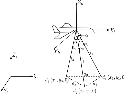
This paper introduces a new UAV navigation system for indoor applications. The introduced navigation system consists of three laser beams that are fixed at the center of the UAV body coordinate frame and they shoot downwards on the ground. Fig. 1 depicts the schematic diagram of the proposed navigation system. The laser beam vectors u1,u2
andu3 form three laser spots on the groundd1,d2 andd3. The global coordinates of the laser dots on the earth frame
XeYeZeare determined by(xi, yi,0)wherei= 1,2,3is the dot number. The ground represents the XeYe plane of the global coordinate system while the axisZeis down toward the center of the earth.a1,a2anda3are the lengths between the laser dots respectively as shown in the diagram. All measurements and values are considered in the earth frame
e unless specified and for simplicity of representation, the index e will not be written. The angle between any two laser beams α ∈ 0,23π
is identical and constant. When
α≥ 2π
3 the laser beams are either in the same plane of the
UAV or shooting upwards opposite to the ground, which is inappropriate and not to be considered. The UAV body frame is denoted by the subscriptband defined by the axesXbYbZb as shown in Fig. 1. For clarity of representation, the negative part of both axes ZeandZb is drawn in this paper.
By knowing the coordinates of the three laser dots (xi, yi,0) i = 1,2,3, the proposed system aims to deter-mine the position of the UAV in the Cartesian coordinates (xv, yv, zv)with respect to the earth frame and the attitude of the vehicle in form of the rotation angles between the earth frame eand body frame b; rollφv, pitch θv and yaw
ψv.
Fig. 1. The schematic diagram of the proposed navigation system.
III. MATHEMATICALFORMULATION
In this work, the navigation problem is formulated as specifying the position and orientation of the UAV from the positions of the three laser dots d1, d2 and d3.
There-fore, the problem now is to obtain the vector P = [xv, yv, zv, φv, θv, ψv] of the vehicle by knowing the po-sitions of the three laser dots (x1, y1,0), (x2, y2,0) and
(x3, y3,0).
In the Cartesian space, see Fig. 1, we have:
l12= (xv−x1)2+ (yv−y1)2+zv2, (1)
l22= (xv−x2)2+ (yv−y2)2+zv2, (2)
l32= (xv−x3)2+ (yv−y3)2+zv2. (3)
wherel1,l2 andl3 represent the length of the laser beams. Using the cosine rule, the laser beam lengths can be calcu-lated by solving the following nonlinear equations for the unknownsl1,l2 andl3:
a21=l21+l22−2l1l2cosα, (4)
a22=l22+l23−2l3l2cosα, (5)
a23=l21+l32−2l1l3cosα, (6)
written as:
a1=p(x1−x2)2+ (y1−y2)2, (7)
a2=
p
(x2−x3)2+ (y2−y3)2, (8)
a3=p(x1−x3)2+ (y1−y3)2. (9)
Solving the nonlinear Eqs. (4)-(6) to obtain the laser beam lengths is not trivial. Nonlinear equations are usually solved by using search methods. In addition to the fact that search algorithms might not converge to the correct solution, they involve computational cost [13]. In order to avoid the non-linearity, the angle between the laser beam can be set to
α = 90◦. In this case, the set of nonlinear equations is simplified and a closed form solution is obtained as:
l1=
r
a2
1−a22+a23
2 , (10)
l2=
r
a2
1+a22−a23
2 , (11)
l3=
r
−a2
1+a22+a23
2 . (12)
Therefore, the configuration ofα= 90◦has the advantage of less computational load. However, as discussed in the next section, setting the angle between the laser beams α= 90◦ implies specific requirement for the used camera to capture the positions of the laser dots on the ground.
Solving Eqs. (1)-(3) forxv,yv and rewriting the solution in the matrix form gives:
xv
yv
= 1 2A
−1B (13)
where
A=
−x1+x2 −y1+y2
−x2+x3 −y2+y3
and
B=
l21−l22+x22+y22−x21−y12 l22−l23+x23+y23−x22−y22
Subsequently,zv is a function ofxvandyv and can be given from Eq. (1) as:
zv=−
q
l2
1−(xv−x1)2−(yv−y1)2. (14)
The negative sign in Eq. (14) is due to the configuration of the earth coordinate system, see Fig 1. Similarly, from Eqs. (2) and (3),zv can be obtained as a function of the position of laser dotd2 and the length of the laser beam vectoru2 or as a function of the position of laser dotd3and the length of
laser beam vectoru3. Note that Eq. (13) has always a unique
solution, and therefore xv and yv can be obtained always whenli,xi andyi,i= 1,2,3 are known. The singularity in matrix A occurs only when ¯a1 k ¯a2, which is not possible
practically because¯a1and¯a2 are two sides in a triangle (¯a1
and ¯a2 are the vectors between d1 and d2, and d2 and d3
respectively).
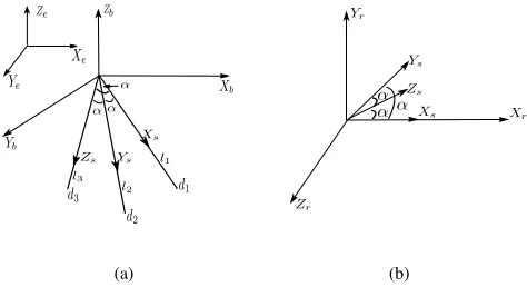
The attitude of the vehicle can be determined by obtaining the rotation matrix from the fixed earth coordinate system to the body coordinate system, see Fig. 2(a). Assuming that the
(a) (b)
Fig. 2. The coordinate system used to develop the proposed navigation system. (a) The earth frame, body coordinate system and the laser beams coordinate system. (b) Transforming the laser beams to an orthogonal coordinate systems.
center of gravity of the UAV coincides with the origin of the laser beams, then the laser beam vectorui in the earth frame can be given as:
ui=RbeR b rT
r su
s
i, i= 1,2,3 (15)
where
us
i: the laser beam vector in the laser coordinate systems.
Tr
s: the transformation matrix from the laser coordinate systemsto an orthogonal coordinate systemr.
Rbr: the rotation matrix from the orthogonal coordinate systemrto the body frameb.
Reb: the rotation matrix from the body frame b to the earth framee.
ui: the laser beam vector in the earth framee. Fig. 2(a) and 2(b) show the coordinate systems used to develop Eq. (15).
In the Cartesian space, we can write:
u1=
x1−xv
y1−yv −zv
, u2=
x2−xv
y2−yv −zv
, u3=
x3−xv
y3−yv −zv
(16) and
us1=
l1
0 0
, u
s
2=
0
l2
0
, u
s
3=
0 0
l3
(17)
wherel1,l2andl3are the lengths of laser beams respectively. From Eq. (15), we write:
U =RebRbrTsrUs (18)
and equivalently this leads to:
Reb =U RbrTsrUs
−1
(19)
=U(Us)−1(Tsr)−1 Rbr−1
(20)
where U =
u1 u2 u3
is a matrix of the laser beam vectors in the earth frame and Us =
us1 us2 us3
is a matrix of the laser beam vectors in the laser frame s. Practically speaking, U and Us exist always and they are nonsingular.
Yr is in the plane XsYs as shown in Fig. 2(b). Then, in order to transfer any vector
xs ys zs T
from the laser
beams coordinate s to a new vector xr yr zr
T
in the orthogonal coordinate systemsr, we write:
xr
yr
zr
=
t11 t12 t13 t21 t22 t23 t31 t32 t33
xs
ys
zs
(21)
wheretij,i, j= 1,2,3represent the elements of transforma-tion matrixTr
s from framesto framer. With the choice of the coordinate frameras in Fig. 2(b), the transfer matrixTr s is given as (see the Appendix for details of the derivation):
Tsr=
1 cosα cosα
0 sinα cosα(1sin−αcosα)
0 0 √
1−3cos2α+2cos3α sinα
, α∈
0,2π
3
(22) Eq. (22) shows clearly thatTsr is not related to the status of the vehicle and therefore it is always fixed.
Rbr represents the rotation matrix from the orthogonal systemrto the body frameb. This rotation matrix is related only to the physical angles between the laser beams and the body of the UAV and therefore it is constant. To obtain
Rb
r, we assume there is no rotation between the global earth system and the zero-time body frame, i.e., the vehicle is in a horizontal alignment with the ground with no yaw rotation before any change in the attitude of the vehicle. At this point of time, Re
b is a unity matrix, i.e.,Reb0 =I3×3. Now, from
Eq. (18) we can write:
Rbr=Rb0
r =U0(U s
0)
−1(Tr s)
−1
(23)
whereU0 and U0s represent the matrices of the laser beam
vectors in the earth frame and laser frame respectively before the vehicle makes any move.
Now, substituting Eq. (23) in Eq. (20) gives:
Reb=U(Us)−1(Tsr)−1 Rbr−1
(24)
=U(Us)−1(Tsr)−1U0(U0s)− 1(Tr
s)
−1−1
(25)
=U(Us)−1(Tsr)
−1
TsrU0s(U0)
−1
(26)
=U(Us)−1U0s(U0)−1 (27)
The standard orientation angles are defined as the rotation angles from etob and this means that the required rotation matrix isRb
e. From Eq. (27), we have:
Rbe= (Rbe)−1=U0(U0s)−1UsU−1 (28)
The general form of the rotation matrix using the rotation anglesφ,θ andψis given in [14] as:
R=
CθCψ CθSψ −Sθ
−CφSψ+SφSθCψ CφCψ+SφSθSψ SφCθ
SφSψ+CφSθCψ −SφCψ+CφSθSψ CφCθ
(29)
where Cx = cosx, Sx = sinx and the sequence of the rotation is considered around Z axis with angleψ and then around theY axis with angleθand finally around theXaxis
with angle φ; i.e., R= R(X, φ)R(Y, θ)R(Z, ψ). Matching the rotation matrix Re
b in Eq. (28) with the general form of the rotation matrix in Eq (29) gives the required attitude anglesφ,θ andψ.
IV. IMPLEMENTATION
The previous section shows that the position and orien-tation of the UAV can be determined when the information about the global position of the three laser dots is available. In order to identify the global coordinates of the laser dots, different techniques can be used. For instance, a fixed camera at the flying area can be used to capture the image of the UAV’s flying path along with the laser dots, analyze this image, determine the laser dots coordinates and then supply the required information to the UAV. This technique needs a communication between the UAV and the ground station to communicate the data of the laser coordinates, which in turn reduces the level of autonomy of the UAV. Moreover, this option can be used in small area where the whole flying path can be captured by one camera. For wide spaces, more than one camera should be used to cover the whole flying path of the vehicle and be able to determine the laser dots.
Another alternative method for obtaining the coordinates of the laser dots is to use on-board camera and do the required analysis on-board. This choice increases the in-dependence of the vehicle and makes the system flexible to be used in different environments. In this case, the global coordinates of the laser dots are calculated by using the coordinates of predefined non movable landmarks. The global positions of landmarks should be known a priori so that they can be used as database to obtain the global position of the laser dots. In details, the process starts by capturing the three laser dots and any landmarks appearing in the view to the on-board camera. Then, a computer vision algorithm can be used to analyze the captured photo and identify its components. When a landmark is recognised in the photo, a mapping matrix between the local position of the landmark in the shot and its predefined global position is calculated. Given that the positions of the laser dots in the captured image relative to the image of the landmark in the same photo shot can be determined easily, the previous mapping data of the landmark positions is used to transfer the laser dots to the global frame and obtain their global coordinates. However, in order for the laser dots to be seen by the camera at all times, a restriction to the angle α between the laser beams applies as shown in the following subsection.
Restrictions to the angle between the laser beams αwhen using on-board camera
length f and an optical sensor dimension s is illustrated in Fig. 3.
Fig. 3. The FoV of the camera.
From Fig. 3, we have:
tanλ= s/2
f =
D/2
z (30)
⇒D=sz
f (31)
wherez is the height of the lens aboveD. For the proposed system in this paper, it is assumed that the lens of the camera is fixed at the center of the UAV and hencez=zv. The three laser dots form a triangle of sidesa¯1,¯a2anda¯3as shown in
Fig. 1. This triangle must fit inside the FoV, and therefore, the circumcircle of radiuskthat passes through the vertices of the triangle should be inside the FoV, i.e., k ≤ D
2. The
relation between the radius of the circumcircle k and the length of the triangle sidesa1,a2 anda3 can be given [15] as:
k=p a1a2a3
(a1 +a2 +a3 ) (−a1 +a2 +a3 ) (a1−a2 +a3 ) (a1 +a2−a3 )
. (32)
Without loss of generality, the laser system can be con-structured in such a way to give a1 = a2 = a3 = a and
l1 =l2 =l3 =l when the UAV is in horizontal alignment with the ground. In this case, we can write:
k= √a
3 (33)
We have kmax=D/2, and this leads to
D/2 = a√max
3 (34)
⇒amax= √
3 2 D=
√ 3 2
szv
f (35)
In the horizontal alignment, the relation betweenzv and the triangled1d2d3 can be defined from Fig. 1 as:
zv2+a
2
3 =l
2
(36)
and from the triangular relations, we have:
a2= 2l2−2l2cosα (37)
From Eq. (36) and Eq. (37), we can write:
cosα= 2l
2−a2
2l2 =
2z2
v−a
2
3
2z2
v+2a
2 3
(38)
Finally,ashould satisfy a≤amax, and this leads to:
cosα≥ 2z
2
v− a2
max
3
2z2
v+
2a2
max
3
(39)
Therefore, using an on-board camera of focal length f and sensor dimensionsimplies that the designed angle between the laser beams has the constraint:
cosα≥2− s2 4f2
2 + s2 2f2
. (40)
In the previous section, it has been shown that makingα= 90◦ has the advantage of simple closed solutions for the laser beam lengths li and therefore it is always preferable to choose α = 90◦. In this case, the camera needs to be specifying according to this predefined angle. Using Fig. 3 with similar analysis to the above derivation leads to:
s f ≥2
√ 2
1−cosα
1 + 2 cosα
0.5
, (41)
and for the special case of α = 90◦, the chosen camera should satisfys≥2√2f.
V. SIMULATIONSTUDY
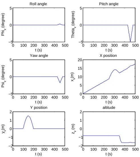
In order to demonstrate the validity of the proposed system, a brief simulation study is conducted. The position and orientation of a simulated UAV is obtained by using the laser navigation system introduced in this paper. The vehicle is flying in a fixed line along Xe for 500 s at a fixed height, fixed speed and horizontal alignment with the ground without rotation, i.e.,φv =θv=ψv= 0. The angle between the laser beams is set to α = 90◦ and hence the length of the laser beams are obtained by using Eqs. (10)-(12). Fig. 4 records the position and orientation of the vehicle during the flight time. At the time t= 100 s, disturbances occur that push the vehicle away from its planned path along
Yeby1.5mand the proposed navigation system records this change as shown in the plot titled “Y position”. Another disturbance is imposed to change the speed of the vehicle along theXein the periodt= 250−350sand the proposed navigation system tracks the change as shown in the plot titled “X position”. In the graph “Z position”, the system records the height of the UAV and the change happens at
t = 350 s from −0.82 m to −1.63 m. Around the time
0 100 200 300 400 500 −5
0 5
Phi
v
(degree)
Roll angle
t (s)
0 100 200 300 400 500 −5
0 5
Theta
v
(degree)
Pitch angle
t (s)
0 100 200 300 400 500 −5
0 5
Psi
v
(degree)
t (s) Yaw angle
0 100 200 300 400 500 0
5 10 15 20
X position
xv
(m)
t (s)
0 100 200 300 400 500 −2
−1 0 1 2
t (s)
yv
(m)
Y position
0 100 200 300 400 500 −2
−1 0 1 2
zv
(m)
altitude
t (s)
Fig. 4. Simulation study for the proposed navigation system.
VI. CONCLUSION
This paper proposes a new, cost-effective and simple navigation system for UAVs. The system is proposed for indoor applications, yet, it can be used also in outdoor missions when the UAV flies at low altitude in plain and predetermined areas. This makes the system ideal for testing stages of mini UAV systems where the possibility of crash is high and it is preferable not to use an expensive navigation system during these flight tests. The system provides full information about the position and orientation of the UAV using three laser beams fixed to the vehicle’s body system and pointing downward to the ground. A computer vision algorithm is needed to identify the dots and determine their positions. The system is more efficient when the angle between the laser beams isα= 90◦ as it becomes possible to get the length of the laser beams without the need for extra sensors or estimation algorithms. A simple simulation study is conducted to show the ability of the proposed navigation system to record the status of the UAV.
APPENDIX
To derive the transformation matrix Tr
s in Eq. (22), we can write from Fig. 2(b):
t11= 1 t12= cosα t13= cosα t21= 0 t22= sinα
t31= 0 t32= 0
The inner products of the unit vectors of Xs andYs gives:
(t12·t13) + (t22·t23) + (t32·t33) =|1||1|cosα
⇒t23= cosα(1−cosα) sinα
In addition, the cosine directions of any vector is equal to1. This gives:
t213+t223+t233= 1
⇒t33= √
1−3cosα2+ 2cos3α
sinα ,
and this makes the matrixTr s as:
Tsr=
1 cosα cosα
0 sinα cosα(1sin−αcosα)
0 0 √
1−3cos2α+2cos3α sinα
, α∈
0,2π
3
REFERENCES
[1] K. P. Valavanis, Ed.,Advances in Unmanned Aerial Vehicles State of the Art and the Road to Autonomy, ser. International Series on Intel-ligent Systems, Control, and Automation: Science and Engineering. Springer, 2007, vol. 33.
[2] P. Vanblyenburgh, “UAVs: An overview,”Air & Space Europe, vol. 1, no. 5-6, pp. 43–47, September 1999.
[3] S. Ehsan and K. D. McDonald-Maier, “On-board vision processing for small UAVs: Time to rethink strategy,” inAdaptive Hardware and Systems, NASA/ESA Conference on, 2009, pp. 75–81.
[4] J. Zhang, Y. Wu, and W. Liu, “Novel approach to position and orienta-tion estimaorienta-tion in vision-based UAV navigaorienta-tion,”IEEE Transactions on Aerospace and Electronic Systems, vol. 46, no. 2, pp. 687–700, 2010.
[5] F. kendoul, I. Fantoni, and K. Nonami, “Optic flow-based vision system for autonomous 3d localization and control of small aerial vehicles,”Robotics and Autonomous Systems, pp. 591–602, 2009. [6] M. R. Parks, “Vision based self motion estimation in a fixed wing
aerial vehicle,” Master’s thesis, Faculty of Virginia Polytechnic Insti-tute and State University, 2006.
[7] J. Courbon, Y. Mezouar, L. Eck, and P. Martinet, “Efficient hierarchical localization method in an omnidirectional images memory,” inIEEE International Conference on Robotics and Automation, 2008, pp. 13– 18.
[8] H. Bay, A. Ess, T. Tuytelaars, and L. V. Gool, “Surf: Speeded up robust features,”Computer Vision and Image Understanding (CVIU), no. 3, 2008.
[9] J. Courbon, Y. Mezouar, N. Nicolas Gu´enard, and P. Martinet, “Vision-based navigation of unmanned aerial vehicle,” Control Engineering Practice, vol. 18, pp. 789–799, 2010.
[10] B. Sinopoli, M. Micheli, G. Donatoy, and T. J. Koo, “Vision based navigation for an unmanned aerial vehicle,” in Proc. of the IEEE International Conference on Robotics an Automation (ICRA 2001, vol. 2, 2001, pp. 1757 – 1764.
[11] A. E. Barabanov and D. V. Romaev, “Design of helicopter autopilot,” inProceedings of the European Control Conference, 2009, pp. 3839– 3844.
[12] D. G. Lowe, “Distinctive image features from scale-invariant key-points,”International Journal of Computer Vision, vol. 60, no. 2, pp. 91–110, 2004.
[13] W. C. Rheinboldt,Methods for Solving Systems of Nonlinear Equa-tions,2nded., ser. CBMS-NSF Regional Conference Series in Applied
Mathematics 70. Society for Industrial and Applied Mathemat-ics(Cambridge University Press), 1998.
[14] H. Schaub and J. L. Junkins,Analytical Mechanics of Space Systems, ser. AIAA Education Series. Reston, VA, USA: AIAA, 2003, vol. 1. [15] D. Pedoe,Geometry: A comprehensive course. Dover Publications,