www.technology.matthey.com
Additive Layer Manufacturing of Catalytic
Static Mixers for Continuous Flow Reactors
Versatile technique provides economic and practical advantages to the
flow chemist
Christian H. Hornung, Shravan
Singh, Simon Saubern*
CSIRO, Bag 10, Clayton South, Melbourne, Victoria 3169, Australia
*Email: [email protected]
With a design guided by computational fluid dynamics (CFD), additively manufactured from base metals and coated with metal catalysts using cold spray technology or electroplating, catalytic static mixers are used to replace fixed bed columns in continuous flow reactors. We have shown their versatility in gas-liquid hydrogenations and homogeneous transfer hydrogenations and review here their preparation, stability and wider use in catalytic transformations using flow reactors. Additive manufacturing provides complex mixer structures that can be retrofitted to existing reactor geometry and reduces manufacturing costs by removing abrasive blasting steps in the mixer fabrication process. The rough surface profile of the mixers aids with high metallurgical bonding of the catalyst coating, as shown by the low catalyst leaching levels reported here.
Flow
Chemistry
–
Economic
Benefits
Over the last decade, much attention has been
focused on continuous flow reactors as a process intensification method to reduce costs. Because of the efficient heat transfer into or out of the narrow
tubing used in these reactors, production of by-products is reduced and often eliminated. This
in turn leads to less need for purification steps,
reducing waste streams and power consumption for a process. Others have noted improved safety aspects such as no vapour headspace, reduced over-all footprint and lower initial capital
expenditure as additional economic benefits to using flow reactors (1–5). Reactions at elevated
temperatures or pressures that might once have been the domain of specialist toll manufacturers could now be brought in-house with dedicated process lines (6, 7).
Continuous flow hydrogenations were some of the earliest reactions investigated in flow reactors
(8–10), resulting in the manufacture of dedicated hydrogenation units from several manufacturers (11, 12). However, these solutions continued to use cartridges or packed columns, essentially
fixed-bed reactors.
Hydrogenations
–
Fixed-Bed
Reactor
Limitations
Fixed-bed reactors have been a mainstay of catalytic reaction processing for many decades. While easy to construct and implement, they suffer from a number of shortcomings when
designing a continuous flow process (1, 9, 13–15). Pressure drop (back-pressure) across a fixed-bed
reactor is a major concern when developing a
flow process, especially with a viscous medium.
This can result in lower throughputs in order to work within the limitations of existing equipment such as pumps, tubing or tubing connectors. Irregular temperature gradients or hotspots are
difficult to remove, especially when scaling to
351 © 2018 Johnson Matthey
Catalytic
Static
Mixers
–
Overview:
Design, Print, Coat
CSIRO has been pursuing a new approach that uses established tubular reactor technology
retrofitted with purposely designed and additively
manufactured catalytic inserts. These are known as catalytic static mixers (CSM) (16). Metal deposition methods such as cold spraying or electroplating are used to coat the base metal scaffold with the catalyst. These metal scaffolds have good mechanical stability, being less brittle than ceramics and more scratch resistant than plastics. They are also compatible with a broader range of solvents and temperatures compared to most plastics and composite materials.
Moreover, the use of additive manufacturing processes means that the CSM can be designed for an existing reactor geometry to optimise
surface contact, mixing and flow. Here, two custom
built reactors are used for hydrogenations, both previously described in other publications (16–18). These contain stainless steel tubing of 6 mm inner diameter and are heated electrically. The smaller unit houses four CSM with a reaction volume of 14 ml (Mk1 reactor) and the larger capacity reactor houses twelve CSM with a 40 ml reaction volume (Mk2 reactor).
Computational
Fluid
Dynamics
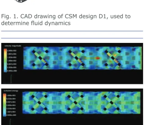
CFD was used to design a mixer with optimised mixing and heat transfer, along with maximum surface area for catalyst deposition. Our simulations for homogeneous liquid and liquid-liquid phases show good performance with low Reynolds numbers typically below 2300. The details of this design and modelling work will be the subject of a forthcoming
publication in the fluid dynamics literature.
Three designs were tested:
• D1 (a continuous mesh style)
• D2 (with a helical groove along the length of
the CSM)
• D3 (a commercial design from Cambridge
Reactor Design Ltd, UK) (16).
Figures 1 and 2 illustrate the CAD drawing and CFD calculations, respectively, for D1.
Additive
Manufacture
Base scaffolds were additively manufactured on an Arcam A1 electron beam melting printer using aluminium alloy, titanium alloy (Ti-6Al-4V), cobalt-chromium alloy (CoCr) or 316L stainless
Fig. 1. CAD drawing of CSM design D1, used to
determine fluid dynamics
Fig. 2. (a) Velocity magnitude; and (b) turbulence energy, from CFD calculations for the design in Fig. 1. Flow from right-to-left
steel powder. An electron beam was used to melt and fuse the metal powders, layer-by-layer, into three-dimensional parts (16–17, 19) as shown in Figure 3. The finished scaffolds for D1 and D2 are
shown in Figure 4. The scaffolds were inserted into metal tubes as illustrated in Figure 5.
Without the need for additional abrasive blasting to create increased surface roughness, the base mixer could be coated in catalyst using either cold spray coating or electroplating.
(a)
Cold
Spray
Coating
Cold spray coating is a technique that sprays metal powders at supersonic speeds onto a target resulting in the metal particles bonding to the target substrate. It produces very stable, controlled coatings. A commercial cold spray unit from Plasma Giken Co Ltd, Japan, was used and base scaffolds were coated with base metals (for example, copper and nickel) as well as precious metals (for example, palladium, platinum and gold).
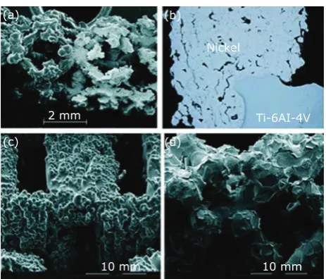
Coating qualities were analysed by scanning electron microscopy (SEM) and optical microscopy (Figures 6(a) and 6(b)) and CSM of high porosity and high metallurgical bonding were used for further investigation in catalytic reactions. This
commercial system was subsequently modified
with a custom-made target holder to rotate
the scaffold at speeds up to 300 rpm (17). This
modification improved surface coverage of the
catalyst on the accessible surface of the scaffold, as well as increasing productivity in processing multiple scaffolds. For additional characterisation data, see previous publications (16–18).
(b) Electroplating
More traditional electroplating using solutions of copper, nickel, palladium or platinum salts were used to provide very high internal plating of the CSM base scaffold (16–18). An example of the electroplated scaffold with copper is shown in Figure 7.
D1
D2
Fig. 4. Photographic images of CSM designs D1 and D2; the design D3 cannot be disclosed
due to commercial confidence – it is available
upon request from Cambridge Reactor Design. Reproduced from (16) with permission from The Royal Society of Chemistry
Fig. 5. A CSM of design D1 fitted inside a tube
Fig. 6. (a) SEM image of a cold sprayed Ni coating on an additively manufactured Ti scaffold (Ti 6Al-4V); (b) optical microscope image of a cross section through a cold sprayed Ni coating and
scaffold at 50× magnification; (c) SEM image
of an electroplated Ni coating on an additively manufactured Ti scaffold; (d) SEM image of an electroplated Pt coating on an additively manufactured Ti scaffold. Reproduced from (16) with permission from The Royal Society of Chemistry
(a) (b)
(d) (c)
Nickel
Ti-6AI-4V 2 mm
10 mm 10 mm
353 © 2018 Johnson Matthey
SEM images (Figures 6(c) and 6(d)) were
used to confirm thickness distribution and,
together with X-ray tomography at the Australian Synchrotron, to analyse the morphology and porosity of the scaffolds. Preparation and characterisation procedures have been published previously (16–18).
Gas-Liquid
Hydrogenations
The first application looked at heterogeneous
hydrogenations combining a substrate in a liquid
phase with hydrogen gas. With a continuous flow
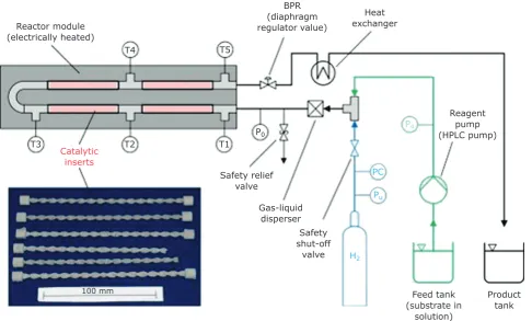
reactor, it is possible to conduct hydrogenations under pressure, but by reducing the volume of material being reacted at any one time, dramatically improve safety considerations compared with hydrogenations using a regular batch reactor. For this work, electrically heated tubular reactors were used that could hold either four or twelve CSM inserted into 6 mm ID stainless steel tubing. A reactor schematic is shown in Figure 8.
Substrate
Stability
Early experience in additive manufacturing in metal within our group came from creating medical implants such as heels or sternums (20–21). These used a titanium alloy, so this was initially chosen as a substrate for the CSM scaffolds. However it became clear that this titanium alloy was subject to hydrogen embrittlement after a few exposures to pressurised hydrogen reactions at temperature (22–24) (Figure 9). Therefore 316L stainless steel was selected as an alternative. This required investigation of new conditions on the electron-beam printing machine, but once these were determined, the problems of CSM scaffold embrittlement were eliminated.
Hydrogenation
Examples
–
Initial
Investigations
Initial investigations looked at the hydrogenation of oleic acid (OA), vinyl acetate (VAc) and cinnamaldehyde (CAL) (see Scheme I for
BPR
Heat (diaphragm
exchanger
Reactor module regulator value)
(electrically heated)
T4 T5
Reagent
T3
Catalytic T2 T1
P0
P4 pump (HPLC pump)
inserts
Safety relief PC
valve
Pu
Gas-liquid disperser
Safety shut-off
valve H2
100 mm Feed tank Product
(substrate in tank solution)
Fig. 8. (a) Simplified process flow diagram of the tubular flow reactor set-up for continuous flow
cinnamaldehyde hydrogenation pathway). Nickel catalyst was applied by cold spray coating and electroplating, as well as platinum catalyst by electroplating, on the titanium alloy, cobalt-chromium alloy and stainless steel (316L) base scaffolds.
While the nickel catalysts generally afforded lower yields and turnover frequencies (TOF) compared to the platinum catalysts, it was apparent that when comparing nickel coated mixers prepared using electroplating to ones prepared using cold-spray,
the cold-spray approach resulted in higher values for yields and TOF. We attribute this to the much smoother surface coatings seen in the electroplated mixers which could contribute to reduced surface area on which the substrate can interact with the catalyst. The results for these substrates are shown in TableI.
A broader range of substrates and functional groups was then investigated (17). For example, the individual isomers of nitroanisole and chloronitrobenzene are cleanly reduced to the corresponding aniline, with the exception of p-nitroanisole (TableII).
For substrates such as phenyl acetylene where multiple products could be produced, the reaction parameters could be tuned to select one product over another, for example favouring styrene over ethyl benzene (Table III). The results from other functional groups, such as imines, diazo compounds, ketones, nitriles and various vinyl systems can be seen in previous publications (16–17).
Active
Pharmaceutical
Ingredients
–
Linezolid
The antibiotic linezolid is used to treat the antibiotic resistant strains vancomycin-resistant enterococci (VRE) and methicillin-resistant Staphylococcus aureus (MRSA). Part of the manufacturing process is a reduction of an aromatic nitro group to an amine as illustrated in Scheme II. A challenge with the existing methodology is the removal of
the palladium catalyst by filtration upon completion
of the hydrogenation and recovery of the catalyst.
By replacing the Pd/C fixed bed reactor with a
palladium coated CSM, the reduction step could be completed with high yield (>99%) and no leaching
of the catalyst, making this a highly efficient
heterogeneous catalytic reactor (25). Fig. 9. The remains of a titanium alloy CSM after
exposure to hydrogenation conditions
CAL
H2
H2
HCAL
HCOH OH
O O
H2 H2 OH COH
Scheme I. Hydrogenation pathway of cinnamaldehyde (CAL),
355
TableIReactionConditions(ReactorPressure,LiquidFlowRate,Gas/LiquidRatioand
ResidenceTime)andResults(Conversion,TurnoverFrequency(TOF)andSpace
TimeYield,(STY))fromHydrogenationExperimentsusingNickelandPlatinum
Catalysts(16)
Reactionconditions Results
Entry Substrate Catalyst p
R,
bar V̇
.
, ml
min−1 G/L τmin , Conv., % TOF,h−1 STY, g l−1h−1
Activation
1 OA Ni-EPCoCr-D1 16 0.5 3.60 6.0 0.8 0.01 1.4 N
Ni-EP
2a VAc 20 0.5 5.00 4.6 14.8 0.55 56 N
CoCr-D1
Ni-EP
3 OA Ti-D1 16 0.5 3.60 6.2 9.4 0.17 56 Y
Ni-CS
4 OA Ti-D1 16 0.5 3.60 6.4 16.1 0.14 93 N
Ni-CS
5 OA Ti-D1 16 0.3 6.67 6.4 19.8 0.11 69 N
Ni-CS
6b OA 16 0.2 10.50 6.5 55.3 0.12 125 N
SS-D3
Ni-CS
7c VAc 22 0.5 5.00 5.0 73.6 0.79 254 N
SS-D3
Pt-EP
8d VAc 24 0.5 5.00 4.7 92.1 35.93 336 N
Ti-D2
Pt-EP
9e VAc 16 0.5 5.00 4.7 100.0 39.02 365 Y
Ti-D2
Pt-EP
10f CAL 20 0.5 5.00 4.7 88.7 17.30 249 N
Ti-D2
Pt-EP
11 OA Ti-D2 16 0.5 3.60 6.1 20.5 4.00 123 N
12 OA X-X-Ti-D1 16 0.3 6.67 6.5 0.0 — — Y
13 VAc X-X-Ti-D1 16 0.3 5.00 5.0 0.0 — — Y
All reactions were conducted at 140°C. For entries 2, 7, 8, 9, 10 and 13, EtOH was used as solvent, for all others EtOAc was used. For entries 2, 7, 8, 9 and 13, the substrate concentration was 2 M, for all others it was 1 M
a p
R was varied between 16 bar and 20 bar resulting in conversions between 8.3% and 14.8% b G/L was varied between 0.92 and 10.50 resulting in conversions between 1.1% and 55.3% c p
R was varied between 10 bar and 22 bar resulting in conversions between 12.5% and 73.6% d p
R was varied between 14 bar and 24 bar resulting in conversions between 57.9% and 92.1%
e Entry 9 was repeated multiple times with and without activation prior to reaction; with activation conversions were between 88.3% and 100.0%; without activation conversions were between 63.5% and 95.1%
f CAL was converted to 88.7%, giving a range of different hydrogenation products: HCOH 16.1%, COH 60.6%, HCAL 7.3%, CAL 11.3%, others 4.6% (See SchemeI)
Reproduced from (16) with permission from The Royal Society of Chemistry
TableIIHydrogenationofIndividualIsomersusingPd-EP-D2inMk2Reactor
Substrate Yields Product
0 20 40 60 80 100
OMe OMe
o
m
NO2 p NH2
0 20 40 60 80 100
Cl Cl
o
m
NO2 p NH2
Adapted from (17) by permission of the author.
TableIIIHydrogenationofPhenylAcetyleneusingNi-CS-D3andMk2Reactor
Conc.,M Pressure, bar Gas/liquidratio,v/v Yield, %
2 12 5
Ethyl benzene
Styrene
Phenyl acetylene
0 20 40 60 80 100
2 16 5
Ethyl benzene
Styrene
Phenyl acetylene
0 20 40 60 80 100
1 24 10
Ethyl benzene
Styrene
Phenyl acetylene
0 20 40 60 80 100
Adapted from (17) by permission of the author.
O
O N F
NO2
H2 gas Pd/CSM
EtOH O N
F
NH2 Further
steps
O N F
N O N H
O Linezolid
357
Leaching
of
Catalyst
–
Results
of
ICP-OES
Monitoring
Over the lifetime of the catalysts, some of which were in operation for up to 2000 h, several leaching tests were conducted. For these, usually an extended run with a common substrate such as VAc (scale: 1 l or more, concentration: 2 M) was used and the combined product from this hydrogenation reaction was collected and analysed for conversion and leaching of metals by inductively coupled plasma-optical emission
spectrometry (ICP-OES) (18). The leaching results are shown in TableIV.
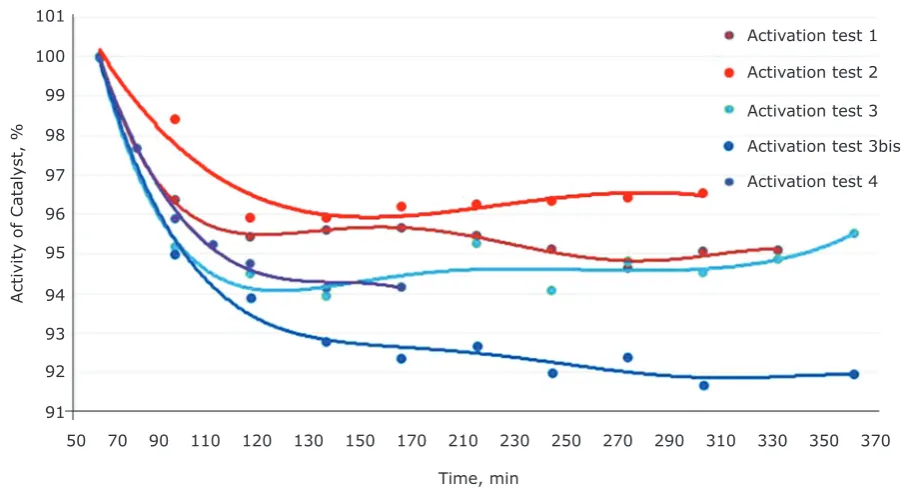
Deactivation of the catalyst in the first few hours
of operation of a VAc reduction using a CSM
coated in nickel using cold spray was also briefly
investigated (Figure 10). An initial drop in activity was seen, but a plateau was reached after 150 min and only around 5% of initial activity was lost. This points to the need to activate and pre-condition the catalyst before use as experiments without activation generally showed lower activity than those where the catalyst was activated.
TableIVAverageConcentrationsforMetalsLeachedfromaNickelCoatedandPalladium
CoatedCSMMeasuredbyICP-OES.BaseScaffoldwas316LStainlessSteelin
Each Case (18)
NickelCSM–Cold
Spray Average conc., ppb PalladiumElectroplate CSM– Average conc., ppb
Cr 27 Pd <0.18
Ni 123.1 Cr 25.2
Fe 408.1 Cu 6.65
– – Mn 0.98
– – Mo 0.35
– – Ni 44.1
– – Fe 32.4
Reprinted from (18) with permission from Elsevier
Activit
y of Catalyst, %
Activation test 1
Activation test 2
Activation test 3
Activation test 3bis Activation test 4 101
100
99
98
97
96
95
94
93
92
91
50 70 90 110 120 130 150 170 210 230 250 270 290 310 330 350 370
Time, min
Fig. 10. Normalised activity levels of Ni cold sprayed onto a stainless steel CSM: VAc (2 M EtOH), H2 (16 bar),
120°C, 1 ml min–1
Homogeneous (Single Phase)
for an intermediate abrasive blasting step, whichTransfer
Hydrogenation
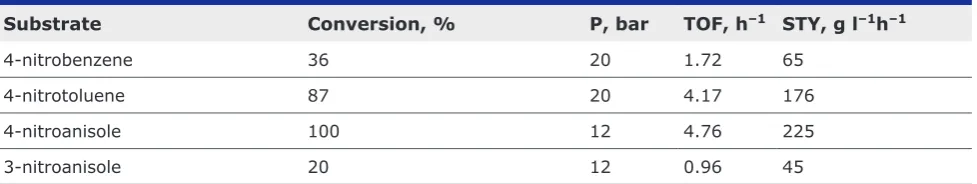
further saves on fabrication cost.We have also looked briefly at transfer hydrogenation
using ammonium formate as the hydrogen source. The early results still need to be optimised, but the smaller reactor containing four of the palladium electroplated CSM using design D1 afforded a series of aniline derivatives by selectively reducing the nitro-groups of the compounds shown in Table V. Additional results for other substrates are listed in a previous publication (17).
Fabrication Costs
A typical CSM printed for a 15 cm length of
6 mm ID tubing found in a mid-sized flow reactor
currently costs between 10% to 70% of the cost to make a comparable static mixer using conventional manufacturing techniques (prior to coating in catalyst) by removing additional welding steps. This is already exceedingly cheap for what is essentially a custom item, but would scale readily if transferred to a production environment, where costs are expected to decrease further by a factor of 1.5 to 10 when additively manufacturing these devices for mass manufacture.
Additional costs then come from the catalyst load and some typical quantities for a 15 cm × 6 mm CSM are shown in Table VI. It should be noted
that the inherent rough surface profile of the
additively manufactured mixers removes the need
Future Directions
CSM is one of the products stemming from a
continuous flow manufacturing focus in our labs,
culminating in the construction of a new 400 m2
flow chemistry facility being built onto existing
infrastructure at CSIRO’s Clayton, Australia, site. CSIRO will provide manufacturing partners with
access to the latest in flow chemistry and process
technology so that they can rapidly develop continuous manufacturing processes to synthesise small molecules, polymers and other materials. We will be partnering with chemical manufacturers
in the pharma, fine chemistry, food and polymers
spaces to utilise CSM in a variety of applications. We are currently exploring the use of copper, nickel, platinum, gold and ruthenium coatings as catalysts for a variety of chemical transformations such as oxidations, hydrogenations and coupling reactions.
Conclusion
This short review article has examined how CSM
have been prepared for use in continuous flow
hydrogenation reactors by making use of in-house
computational fluid dynamic design capability,
metal additive manufacturing and catalyst coating abilities at CSIRO. While 316L stainless steel is the obvious choice of scaffold for most chemistries,
TableVExamplesofTransferHydrogenationonPalladiumusingAmmoniumFormate
Substrate Conversion, % P, bar TOF,h–1 STY, g l–1h–1
4-nitrobenzene 36 20 1.72 65
4-nitrotoluene 87 20 4.17 176
4-nitroanisole 100 12 4.76 225
3-nitroanisole 20 12 0.96 45
Conditions: 130°C, 0.33 M in MeOH, 1 ml min–1. Adapted from (17) by permission of the author
TableVITypicalLoadingsofa15cm×6mmCSMProducedontheArcam2000Printer,
FollowedbySprayCoatingwiththeSpray&Wipe3000Unit
Basematerial Weight,g Metal/Coatingmethod Weightwithcatalyst,g
Ti alloy – design D1 11.3 Ni / CS 13.3
SS 316 – design D3 15.6 Ni / CS 18.9
Ti alloy – design D2 16.2 Pt / EP 16.6
359 © 2018 Johnson Matthey
other alloys using titanium, aluminium or cobalt-chrome could also be used. But we found, as have others, that the titanium alloy was not suitable for use in hydrogenation reactions due to its limited stability after prolonged exposure to hydrogen.
Either cold-spray technology or electroplating may be used to coat the CSM scaffolds with metal catalysts, with little leaching being observed after several months for either technique. SEM studies indicated that the former method produces a rougher coating and thus higher surface area, while the latter method coats more of the internal surfaces of the scaffold.
The CSM performed well in gas-liquid hydrogenations and homogeneous transfer hydrogenations, on a variety of substrates and with improvements in the space time yield (STY) for these reactions. Selective hydrogenation could be achieved by careful tuning of the hydrogenation conditions, allowing, for example, the reduction of phenyl acetylene to either styrene
or ethylbenzene. Significantly, the combination of
design capability, additive manufacturing in metal and stable catalyst coating has provided a safe alternative
to fixed bed reactors for existing hydrogenation continuous flow reactors. We remain excited to see
this approach extended to other catalytic reactions in
continuous flow reactors.
Acknowledgements
CSIRO would like to thank Bashir Harji of Cambridge Reactor Designs, UK, for the design of our Mk1 hydrogenation reactor. The authors would like to thank Darren Fraser for the animation stills of the Arcam electron-beam printer and the additive manufacturing of the CSM scaffolds, Mike Horne and Bita Bayatsarmadi for electroplating the mixers, Andrew Urban for cold spraying the mixers and Dayalan Gunasegaram for the CFD images of the mixers, all of CSIRO, Australia. Finally, we would like to thank Antoine Avril for the photographs of the disintegrated Ti-mixers and Antony Carafa for data processing of the extended run experiments.
References
1. J. Wegner, S. Ceylan and A. Kirschning, Chem.
Commun., 2011, 47, (16), 4583
2. F. Darvas and G. Dormán, ‘Fundamentals of Flow
Chemistry’, in “Flow Chemistry: Fundementals”, eds. F. Darvas, G. Dormán and V. Hessel, Vol. 1, Walter De Gruyter GmbH, Berlin, Germany, 2014, pp. 9–58
3. L. N. Protasova, M. Bulut, D. Ormerod, A.
Buekenhoudt, J. Berton and C. V. Stevens, Org.
Process Res. Dev., 2013, 17, (5), 760
4. M. Baumann and I. R. Baxendale, Beilstein J. Org.
Chem., 2015, 11, 1194
5. R. Porta, M. Benaglia and A. Puglisi, Org. Process
Res. Dev., 2016, 20, (1), 2
6. B. Gutmann, D. Cantillo and C. O. Kappe, Angew.
Chem. Int. Ed., 2015, 54, (23), 6688
7. M. Movsisyan, E. I. P. Delbeke, J. K. E. T. Berton,
C. Battilocchio, S. V. Ley and C. V. Stevens, Chem. Soc. Rev., 2016, 45, (18), 4892
8. P. J. Cossar, L. Hizartzidis, M. I. Simone, A.
McCluskey and C. P. Gordon, Org. Biomol. Chem.,
2015, 13, (26), 7119
9. C. Brechtelsbauer and K. K. Hii, ‘Catalysis in Flow’,
in “Flow Chemistry: Applications”, eds. F. Darvas, V. Hessel and G. Dormán, Vol. 2, Walter De Gruyter GmbH, Berlin, Germany, 2014, pp. 3–30
10. C. de Bellefon, ‘Catalytic Engineering Aspects of Flow Chemistry’, in “Flow Chemistry: Applications”, eds. F. Darvas, V. Hessel and G. Dormán, Vol. 2, Walter De Gruyter GmbH, Berlin, Germany, 2014, pp. 31–62
11. R. V. Jones, L. Godorhazy, N. Varga, D. Szalay, L. Urge and F. Darvas, J. Comb. Chem., 2006, 8, (1), 110
12. J. Singh, Chim. e Ind., 2011, 93, (8), 132 13. J. Yue, Catal. Today, 2018, 308, 3
14. B. R. Vaddula, R. S. Varma and M. A. A. Gonzalez,
Curr. Org. Chem., 2013, 17, (20), 2268
15. T. Chinnusamy, S. Yudha S, M. Hager, P.
Kreitmeier and O. Reiser, ChemSusChem, 2012,
5, (2), 247
16. A. Avril, C. H. Hornung, A. Urban, D. Fraser, M. Horne, J.-P. Veder, J. Tsanaktsidis, T. Rodopoulos,
C. Henry and D. Gunasegaram, React. Chem.
Eng., 2017, 2, (2), 180
17. C. H. Hornung, X. Nguyen, A. Carafa, J. Gardiner, A. Urban, D. Fraser, M. D. Horne, D. R. Gunasegaram and J. Tsanaktsidis, Org. Process Res. Dev., 2017,
21, (9), 1311
18. X. Nguyen, A. Carafa and C. H. Hornung, Chem.
Eng. Process. Process Intensif., 2018, 124, 215
19. “CSIRO Additive Manufacturing of Metals”,
CSIRO, online video clip, CSIRO, YouTubeGB ,
13th January, 2013
20. ‘CSIRO Produces 3D Heel in World First Surgery’, CSIRO, Canberra, Australia, 22nd October, 2014
21. A. Knight, ‘Cancer Patient Receives 3D Printed
Australia, 11th September, 2015
22. ‘Safety Standard for Hydrogen and Hydrogen
Systems: Guidelines for Hydrogen System Design, Materials Selection, Operations, Storage and Transportation’, NSS-1740.16-Rev, Office of Safety and Mission Assurance, NASA, Washington DC, USA, 1st January, 1997
23. A. Barnoush and H. Vehoff, Acta Mater., 2010, 58, (16), 5274
24. D. S. Shih, I. M. Robertson and H. K. Birnbaum,
Acta Metall., 1988, 36, (1), 111
25. J. Gardiner, C. H. Hornung, X. Nguyen, A. J. Urban, D. Fraser, D. Gunasegaram, M. D. Horne and J. Tsanaktsidis, ‘Continuous Flow Hydrogenations Using Catalytic Static Mixers: Application to a Key Pharmaceutical Intermediate of Linezolid’, Poster 646, 18th Tetrahedron Symposium Asian Edition, Melbourne, Australia, 24th–26th July, 2017
The Authors
Christian Hornung is a trained chemical engineer and he currently leads CSIRO’s Centre for Industrial Flow Chemistry, FloWorks. Dr Hornung has several years’ experience working
in the flow chemistry and reactor technology area on the interface between chemistry
and engineering. He works in multidisciplinary teams involved in the development of new chemical and polymer products and novel reactor solutions, combining additive manufacture with catalysis.
Shravan Singh is an electronic engineer and currently works as Business Development Manager at CSIRO Manufacturing. Prior to joining CSIRO, Shravan worked for himself as an entrepreneur and has years of experience in optical metrology, having worked at leading metrology institutes in South Africa and the USA in technical and management roles. He forms part of a multidisciplinary team at CSIRO that includes intellectual property, commercialisation and legal experts, helping CSIRO researchers translate their work into the market.
Simon Saubern trained originally as an organic chemist and, with a keen interest in
high-throughput experimentation, facilitated CSIRO’s early flow chemistry capability. He has several years’ experience working with continuous flow reactors on industrial processes, particularly in the field of polymer synthesis. Dr Saubern is part of the multidisciplinary FloWorks team, evaluating novel technologies applied to synthesising polymers in flow