ISSN (Online): 2320-9364, ISSN (Print): 2320-9356
www.ijres.org Volume 3 Issue 6 ǁ June 2015 ǁ PP.48-54
Contact high-precision large stroke thread measuring instrument
Zhang Yunfeng
,
Fan Zhongming
,
Lin Pengpeng
(
College of Mechanical Engineering
,
ShangHai University of Engineering Science, Shanghai
,
201620
,
China
)
Abstract:
Threaded parts are the most widely used mechanical parts in mechanical industry, higherrequirements on its detection technology. Thread parameter detection method can more fully reproduce the actual
situation of thread according to the facts, in order to thread as a judge on the basis of comprehensive status,
ensure the quality of the thread. In this paper, on the basis of detailed analysis of thread measurement device at
home and abroad, developed a contact high precision large stroke thread measuring instrument. Measured
thread surface profile, the instrument scanning grating with high precision and high precision micro
displacement mechanism were recorded in the horizontal and vertical directions of the scanning process
numerical changes, the data were analyzed by computer, measured thread to generate two-dimensional contour
graphics, calculated to obtain all parameters of the screw to be tested.
Keywords:
contact; scanning ;thread measurementI.
INTRODUCTION
Thread is most widely used mechanical design and manufacturing field parts, precision of screw thread
parameters of the detection is a worldwide problem. Universal tool microscope, such as is the use of imaging
principle of measuring multiple parameters of the screw thread, but can only measure the external thread,
measuring accuracy is affected by the spiral Angle, high surface quality requirement of thread. Laser
interferometer to measure thread, the thread surface quality, tooth type Angle, the external environment, the
influence of such factors and measuring instrument cost is higher. Contact is thread parameter measurement is an
important research direction, a thread can be measured more parameters, high measurement precision, high speed,
wide range, can measure the internal thread. The Dutch IAC MSXP series screw thread gauge, expensive,
measure the length of the thread is shorter; Xi 'an jiaotong university developed oil pipeline screw thread
measuring machine specially designed for field measurement of oil pipeline thread; Beijing university of
technology of the pipe joint internal thread measuring device is only for measuring pipe joint internal thread. In
view of the imaging method of thread detection and laser detection strict measuring conditions; The contact thread
measuring instrument is expensive, with short length of thread and limited factors, such as measuring thread sort,
II. STRUCTURAL DESIGN OF THE INSTRUMENT 1. Measuring principle
Fig. 1 contact thread measuring principle diagram
Making uniform motion drive system drives the workbench, needle with the thread contour surface of
ups and downs do up and down. Needle movement and the movement of the workbench signals by the rod is
passed to the electronic device, electronic device to enlarge the signal and transformation, through processing and
calculation of the software system, finally be measured on the surface of the screw thread 2 d contour graphics,
further in calculating the parameters of screw thread. Contact relative to non-contact measurement is reliable in
operation is simple, intuitive, and the advantages of stable performance, strong commonality, is currently the best
thread measurement method.
2. Mechanical device
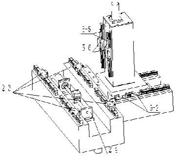
High-precision large stroke thread measuring instrument includes base parts, fixture components, X
1-1 base ; 1-2 adjustable support leg ;2-1 X workbench;2-2 X direction guide rail;2-3 X direction guide rail
slider;2-4 X direction transmission system;2-5 X direction grating ruler; 2-6 X direction moving grating; 3-1
thimble rack locking bolt and nut; 3-2、3-6 thimble rack;3-3、3-8 the top locking bolts; 3-4、3-7 tops; 4-1 needle;
4-2 micro displacement box;5-1 column;5-2 column parts (Z direction) grating ruler;5-3 column parts (Z
direction) moving grating;5-4 column parts (Z direction) transmission system;5-5 column parts (Z direction)
guide rail;5-6 column parts (Z direction) guide rail slider;6-1 Y workbench; 6-2 Y direction guide rail slider;
6-3 Y direction guide rail; 6-4 Y direction transmission system;6-5 Y direction grating ruler;6-6 Y direction
moving grating.
Fig. 2 high-precision large stroke thread measuring instrument structure schematic diagram
X direction transmission system fixed base, drive X workbench along the X direction guide rail
movement; X direction guide rail and X direction grating ruler are installed on the base, the X direction moving
grating and the X direction guide rail slider are installed on the X workbench. When X workbench with base in
relative motion, grating ruler component to measure the displacement of X workbench and feedback to the control
system. The column is installed on the Y workbench, column parts (Z direction) transmission system installed
inside the column. Column parts (Z direction) transmission system drive Micro displacement box and the
movement is perpendicular to X workbench; column parts (Z direction) grating ruler and column parts (Z
direction) guide rail are installed on the column, column parts (Z direction) moving grating and column parts (Z
direction) guide rail slider are installed on the micro displacement box. When micro displacement box and column
of relative movement occurs, grating ruler component to measure micro displacement box of displacement and
feedback to the control system; When the needle is scanned by the screw thread, the surface of the workpiece is
measured with a tiny upper and lower displacement movement. The micro displacement is fed to the control
system with the feedback of the micro displacement. Y direction transmission system fixed base, drive Y
workbench along the Y direction guide rail movement; Y direction guide rail and Y direction grating ruler are
installed on the base, the Y direction moving grating and the Y direction guide rail slider are installed on the Y
workbench. When Y workbench with base in relative motion, grating ruler component to measure the
displacement of Y workbench and feedback to the control system. Adjustable support leg mounted at base bottom
surface. Thimble rack is installed on the X workbench, thimble rack locking bolt and nut and tops are respectively
arranged on the thimble rack, thimble rack locking bolt and nut connecting X workbench and thimble rack for the
thimble rack lock on the X workbench.
3
.
working process
Top fixture clamps screw thread workpiece. Through thread axis parts and perpendicular to the surface
locating the relative position of the upper and lower profile surfaces of the measured screw workpiece. The T type
needle is scanned in the upper and lower profile surfaces of the measured plane. Superposition of two values
which the displacement of the micro displacement components and the displacement of the micro displacement of
the needle as the thread profile radial coordinate values under test. Displacement of X workbench as thread
surface profile axial coordinate values on the corresponding points. Each contour point of the scan is
corresponding to a two-dimensional coordinate value. To deal with the data obtained, get measured on the surface
of the screw thread two-dimensional contour graphics, calculation for each thread profile parameter values.
III.
E
LECTRICAL DESIGN OF THE INSTRUMENTThe electrical system is the important part of high-precision large stroke thread measuring instrument,
which mainly includes the control circuit, the measurement circuit and the computer. Computer collection of three
coordinate direction of the grating measuring signal, through the control circuit control the movement of X/Y
workbench, micro displacement box and measuring needle, the resulting closed loop control system can
effectively complete the whole measurement process.
1. control circuit
In the process of the control, circuit is mainly used for the measurement or adjustment in mobile
positioning and mobile displacement variation to X, Y and Z three directions. In three directions of movement
control, Computer send out mobile instruction, according to the needs of user,the analog power is obtained by
A/D conversion. The computer controls the transmission system in all directions to drive the X/Y workbench and
the micro displacement box to move along the guide rail of the respective direction, the change of displacement is
collected by the grating ruler in every direction, and the data is processed by real-time feedback to computer. The
computer sends out the stop instruction to reach the predetermined mobile displacement, and the transmission
system stops the action of the direction., as shown in Fig. 3.
computer
Motion control module
X screw mechanism
Z control motor Y control motor
X control motor
Z screw mechanism Y screw mechanism micro displacement box Y workbench X workbench g r a t i n g X g r a t i n g measuring needle Z g r a t i n g Z d i r e c t i o n d a t a a c q u i s i t i o n m o d u l e X d i r e c t i o n d a t a a c q u i s i t i o n m o d u l e
Fig. 3 high-precision large stroke thread measuring instrument control system block diagram 2. Measurement circuit
directions. They have in each direction displacement variation through their direction of the grating for data
collection, the subdivision circuit breakdown them into the computer through the I/O interface, after data
conversion and processing, the displacement variation of the direction is obtained. X, Y, Z directions of the mobile
is accompanied by a grating measuring signals, each signal processing principle and circuit of all the way. as
shown in Fig. 4.
grating
signal
amplifier,
detection
filter
A/D, I/O
interface
computer
control
circuit
The workbench/micro displacement
components
Fig. 4 high-precision large stroke thread measuring instrument flow diagram
Needle and thread being measured workpiece surface contact, the X workbench is driven by the
transmission system, the needle is moved along the surface of the screw workpiece at a constant speed, Measured
by the needle on the surface of the peak valley make fluctuation displacement, Each direction grating obtains the
displacement signal, which causes the AC carrier wave to change. This change after amplification, demodulation,
filtering circuit, then converted into digital signal and stored in the computer system memory. The original
contour information is digitally filtered by the computer, the surface profile of the screw is separated and its
parameters are calculated.
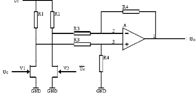
2.1 amplifying circuit
The grating converts optical signal into light current by the photoelectric conversion circuit, and the
change of the displacement is proportional to the change of the current. Usually the output signal of the grating is
small, so it is necessary to amplify the sensor signal. The principle is shown in Fig. 5.
Fig. 5 amplifying circuit
2.2 switch phase-sensitive detection circuit
Detection circuit is demodulating the output signal of the amplifier, in order to obtain consistent with
threaded workpiece contour graph of graded DC signal. In order to make the detection circuit has the ability of
identifying the signal phase and frequency selective, it need to adopt the phase-sensitive detection circuit. From
the structure of the circuit, phase sensitive detection circuit is mainly characterized in that, in addition to the
frequency of the input signal. The reference signal shall have the same frequency as the amplitude modulation
signal of the desired demodulation, and the carrier signal can be used as the reference signal to meet the condition.
This instrument adopts the switch square-wave multiplication phase sensitive detector, because this kind of
detector conforms to the trend of miniaturization and integration of the circuit. Its working principle is shown in
Fig. 6.
Fig. 6 switch phase-sensitive detection circuit 2.3 active low-pass filter circuit
The signal obtained from the grating in the measurement system often contains noise and many signals
unrelated to the measurement. the original measured signal which through transmission, amplification,
transformation, operation, and various other process, will be mixed with various forms of noise. They affect
measurement accuracy. These general random noise is very strong, it is difficult to directly separated from the
time domain, but limited to its mechanism, the noise power is limited, and distributed in the frequency domain
according to certain rules. Minimum standards of beard needle tip radius of 2 microns, so rough distance is less
than 2 microns signals are not of the thread surface contour. X workbench to 1 mm/s speed of movement, needle
reflects to no greater than 500 Hz frequency for vertical movement, higher than the frequency of the signal
component is not a thread surface outline signal, but is caused by noise interference signals and electrical
components. Therefore, the filter should be used to filter the signal above this frequency. In this instrument, the
design of active low pass filter is shown in Fig. 7.
Fig. 7 active low-pass filter circuit
3. Data collection
The instrument choose AC1059 multi-function data collection card 12 bit A/D board. AC1059 has 16
channel analog input (single side); Input programmable amplifier G = 1, 2, 5, 10 times; Board a 16-bit timer can
automatically control the sampling speed 10 µs - 65 ms/s time, 1µs clock benchmark; Multiple working modes;
software or hardware interrupt; 24 programmable digital I/O (8255); 12 bit D/A converter and 16 bit counter
(8253) can be applied to digital pulse counting or frequency measurement. According to Nyquist theorem,
determine the sampling points. Determine the sampling frequency by setting the timer on the A/D board. For
example: the sampling length is 0.8 mm, sampling points are 1600 points. Due to the driver box at the rate of 1
mm/s, so the sampling frequency is 2000 Hz, the sampling interval is 500µs.
IV. CONCLUSION
In this paper, contact high-precision large stroke thread measuring instrument is studied. Feed direction
of the micro displacement measuring needle parts is perpendicular to the direction of needle scanning thread
workpiece in the instrument, which increase the size of the measured screw workpiece type, so that the application
of the instrument range increases. The mechanical parts of the instrument structure is relatively simple, the
equipment cost is low. The study of the instrument is significant progress and application value.
REFERENCES
[1] K. Develi, T. Babadagli, and C. Comlekci, A new computer-controlled surface-scanning device for measurement of fracture surface
roughness ,Computers & Geosciences,27(13),2001, 265–277.
[2] Anita Avisane, Didzis Avisans, Contact Deformations under the Influence of Measurement Force, Procedia
Engineering,100(25),2015,569-57.
[3] Yang Liua, Ekaterina Pavlovskaiab, Marian Wiercigrochb, Zhike Peng,Forward and backward motion control of a vibro-impact
capsule system, International Journal of Non-Linear Mechanics, 70(9),2015,30-46.
[4] Melvin R. Corley, E.Eugene Callens Jr. ,Herbert G. Tull III, Direct contact profile characterization of thread surfaces, Journal of
Manufacturing Systems, 11(5),1992,309-313.
[5] Xie Tiebang ,Sun Yanling,Contact surface topography based on vertical displacement scanning, Automatic instrument,
27(7),1992,19-21.
[6] Pietro G. Morasso, Motor Control Models: Learning and Performance, International Encyclopedia of the Social & Behavioral