ISSN 2347-4289
Improvement Of Heat Transfer Performances Of
Biomangnetic Flow In A Rectangular Duct Under
Different Types Of Magnetic Fields
Haleh Alimohamadi, Vahid Dehghan-Niri, Parisa Sarmadi, Mehdi Ashjaee
Department of Mechanical Engineering, Collage of Engineering, University of Tehran, Tehran, Iran; Department of Mechanical Engineering, Collage of Engineering, K.N.Toosi University, Tehran, Iran;
Professor, Department of Mechanical Engineering, Collage of Engineering, University of Tehran, Tehran, Iran;
ABSTRACT: In this work the impact of different types and numerous numbers of magnetic fields on a Newtonian biomagnetic fluid is introduced. This external force causes vortexes formation on the lower plate where the magnetic field is applied. Where the magnetic field is located shear stress increases sharply and the range of this parameter on the lower wall in FHD survey is 30% shorter than MHD. Another significant effect of applying magnetic force is increasing the amount of heat transfer. If one and seven dipoles locate below the duct, the value of Nusselt number increases 9.5% and 30 % due to the magnetization force only. In MHD analysis Nu is 2.5 times higher than simple case without magnetic force. In the other case, the increment of Nusselt number due to magnetization force of seven wires is just 20% and if the electrical conductivity of the blood is considered the Nusselt number can reach to 70% maximum theoretical Nusselt number which obtains by seven dipoles.
Keywords: Biomagnetic, Nusselt Number, MHD and FHD Analysis, Heat Transfer
1 INTRODUCTION
Nowadays,the increment of the heat transfer is a critical problem in cooling systems, heat exchangers, electrical devices and even medical science. One of the new ideas is adding nanoparticles particles to the fluid, which have magnetization feature, because the flow can be affected by the magnetic field. The mixture of solid particles and fluid is called nanofluid, but in most cases the mixture can beassumed as single phase fluids..During the last decades, numerous investigations have been done in this area. At first step, increasing the thermal properties of nanofluids rather than their basic fluids was found [1]. Many authors focused on the determining convection coefficient in the laminar and turbulent regime [2]. The enhancement of entropy and heat transport performance due to nanoparticles in fluid was studies in [3-5]. Recently, biofluids such as blood become popular and extensive researches are done in this field because this new idea has many usages in drug delivery, treatment of cancer and tumors. In the beginning stage, a mathematical model for natural biomagnetic fluid base on the Ferro –hydro-dynamic (FHD) principles was suggested [6]. However, experimental data exhibits that blood has remarkable electrical conductivity; as a result, for obtaining accurate results, it is essential to consider Lorentz force which happens due to Magneto-hydro-dynamic (MHD)[7].
2
M
ATHEMATICAL FORMULATION2.1 Magnetization Equation
Magnetization property (M) is a feature of biofluid which determines the impression of magnetic field. In this paper the formula which relates the magnetization to magnetic field strength and temperature is used [8]:
( c )
MKH T T
(1)
Where K is a constant and Tc is the Curie temperature. In this work, a viscous, laminar, incompressible, steady and two dimensional biofluid flows between two parallel and
impermeable flat plate. We suppose the flow at the entrance of the duct is fully developed. The temperature of plates are constant (T1 and T2) while T1>T2. The length and height of the duct are L and h respectively. Different types of magnetic fields are placed below the lower plate. The fluid is assumed has Newtonian behavior and its electrical conducting is noticeable. As it mentioned before, two kinds of forces affect the biofluids. One of them is magnetization force which appears due to gradient of magnetic field and the second one is the Lorentz force which is important because of high electrical conductivity..
2.2 Transformation of Equations
In order to solve easily the coupled systems of equations the following non-dimensional variables are introduced
* x x
h
y* y h
*
r u u
u
*
r v v
u
*
2 r p p
u
*
0 H H
H
* 1
1 2
T T T
T T
(2)
The maximum velocity profile at the entrance of the duct is ur and H0 is the magnetic field strength at the point above the position of magnetic field on the lower wall. The equations 1, 2 and 5 are changed to the below forms:
* *
* 0 *
u v y x
(3)
2 2 2
* * * *
* * * *
* * *
2 * 2 *
* * * * *
* *
* 1
( ) ( )
Re Re
F
M
x y y
u u p H
u v Mn T H
x y x x
Mn
u u
v H H u H
x y
(4)
2
2 2
* * * *
* * * *
* * * *
2 * 2 *
* * * * *
* *
1
( ) ( )
Re Re
F
M
x y y
v v p H
u v Mn T H
x y y y
Mn
v v
u H H v H
x y
2
* * * *
* * * * * *
* * * *
2 * 2 * * * * * 2
2 *
* * * *
2 2 2
* * * *
( ) ( )
1
( ) ( )
Re Re* Pr *
2( ) 2( ) ( ) Re
F
M
y x
T T H H
u v Mn Ec T H u v
x y x y
Mn T T
Ec u H v H
x y
Ec u v v u
x y x y
(6)
The non-dimensional parameters which appear in the above equations are:
*
Re h u
(Reynolds number) (7)
1
1 2
T
T T
(Temperature number) (8)
2 1 2 ( ) r p u Ec
C T T
(Eckert number) (9)
Pr Cp k
(Prandtl number) (10)
2
0 0 1 2
2
( )
F
r
H K T T Mn
u
(Magnetic number of FHD) (11)
2 2 0 0 M
H h
Mn
(Magnetic number of MHD) (12)
2.3 Boundary Condition
In order to solve equations3, 4, 5 and 6 simultaneously the below non-dimensional boundary conditions are applied:
2 *
* * *
* @x 0 and 0 y 1: u 4y 4y , T 0
x
(13)
* * *
* * *
@x 7 and 0 y 1: u v T 0
x y x
(14)
* * * *
@y0,1 and 0 x 7 :u v 0,T down0,T up1 (15)
2.4 Applications
This paper discussedon the effects of increasing the numbers of two differnet types of magnetic filed on the average Nusselt number, velocity and temperature countours, shear stress and the outlet temperature of the fluid. In case I, the magnetic fieldsare produced by seven magnetic dipoles which are placed at distance b below the lower in consecutive positions a1,a2,a3,a4,a5,a6 and a7. The component of the each dipole magnetic field intensity Hx and Hy along the x-and y-axes are given[9]:
2 2
2 2 2
(( ) ( ) ) 2 (( ) ( ) ) x
x a y b
H
x a y b
, 2 2 2
2 ( )
2 (( ) ( ) )
y
x y b H
x a y b
(16)
γis the magnetic field strength at x=a and y=b.
In case II, the magnetic field is generated by the electrical current which passes through a straight wire and the wire is plumb to x-y plate. In this condition, the magnetic field
intensity is expressed by:
2 2
( )
2 (( ) ( ) )
x
x a H
x a y b
, 2 2
( )
2 (( ) ( ) )
y
y b H
x a y b
(17)
The COMSOL Multiphasic software is used in the mapped
discrete domain.
3
R
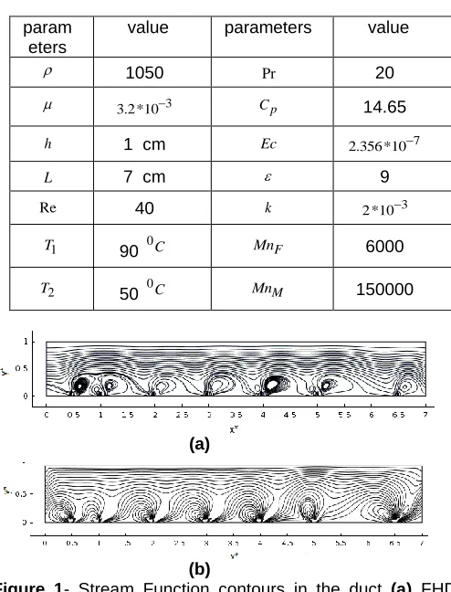
ESULT AND CONCLUSIONThe constant values that are used in this paper are described in
Table 1[10]. Figure 1 demonstrate the stream function
contours of flow as the magnetic fields of electrical current through the seven same wires influence it. These wires are plumed to the x-y plate and pass the points x=0.5, x=1, x=2, x=3, x=4, x=5 and x=6.5 respectively.
Table 1 - constant value
(a)
(b)
Figure 1- Stream Function contours in the duct (a) FHD analysis , (b) MHD analysis
As it is seen, in seven points the flow circulates on the lower plate where the magnetic field is applied and seven vortexes are createdthere. In Figure 1(a), the Lorentz force is omitted,so the formed vortexes are smaller than Figure 1(b)
para meters
value parameters value
1050 Pr 20
3.2*103 Cp 14.65
h 1 cm Ec 2.356*107
L 7 cm 9
Re 40 k 2 *103
1
T 90 0C MnF 6000
2
T 50 0C MnM 150000
param eters
value parameters value
1050 Pr 20
3.2*103 Cp 14.65
h 1 cm Ec 2.356*107
L 7 cm 9
Re 40 k 2 *103
1
T 90 0C MnF 6000
2
ISSN 2347-4289
and they can influencethe restricted region,
(a)
(b)
Figure 2- Temperature contours of folw (a) FHD analysis ,
(b) MHD analysis
(a)
(b)
Figure 3- non- dimensional velocity profile component (u) at various positions (a) FHD analysis , (b) MHD analysis
The temperature contours of flow are shown in Figure 2. Similar to Figure 1 seven vortexes are appeared on the lower plate. By considering the Lorentz force, these vortexes are bigger and stronger. The non-dimensional velocity profile component (u) against y axis at four positions
is illustrated in
Figure 3. When the Lorentz force is applied, the whole of fluid is moved with higher speed and as it seen the maximum velocity in case (b) is 3.5 times higher than case (a) .In both cases near the lower plate the x velocity becomes negative which causes separation and vortexes formation. Figure 4 shows the non-dimensional temperature profile at four positions along the x axis. At first view, exerting magnetic field deviates the temperature line from straight shape and shifts it to the higher value. It means that the convection coefficient has increased and the flow has
the ability to absorb more heats. In addition, by considering the Lorentz force, almost all points in the domain experience higher temperature than exerting magnetization force only which is beneficial for medical science (See Figure 4).
(a)
(b)
Figure 4- non- dimensional temperature profile at various position (a) FHD analysis , (b) MHD analysis
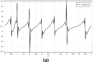
The variation of shear stress along the length of duct on the lower late is illustrated in Figure 5. The pickvalues of shear stress in the lower wall occur at applied magnetic field positions. After that, the value of this parameter declines sharply and it receives to negative amount which causes reversing the flow and vortices formation.In MHD analyze the shear wall on the lower plate amends in far-reaching range [-120,160]whereas in FHD procedure, this range 30% decreases.
(b)
Figure 5- Variation of shear stress on the lower platealong the length of duct (a) FHD analysis , (b) MHD analysis
Nusselt number is a significant parameter which defines the amount of heat that transfer from the plates to the fluid. The value of this parameter on the upper and lower plates for two kinds of magnetic field (wire and dipole)for FHD and MHD analysisfor the same value of magnetic numbers,arearchived in Table 2 and Table 3
Table 2- Avearge Nu on the upper and lower platesby applying magnetic filed of dipoles
Differe nt number
s
Nummagnitude in
FHD analysis
Nummagnitude in
MHD analysis
low er plat e
uppe r plate
t Nu
lowe r plat
e
uppe r plate
t Nu
Without magneti
c field
1 1 2 1 1 2
1dipole 1.1
3 1.06 2.19 1.55 1.03 2.5
8
3 dipole 1.1
4 1.16 2.3 2.38 1.08 3.4
6
7 dipole 1.3 1.28 2.58 4.12 1.08 5.2
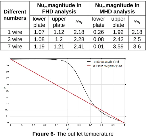
As it seen in Table 2, by applying one dipole at the location x=3 and y =0.2, the total Nusselt number on the lower and upper plate increases 9.5% and if seven dipoles place below the duct at x=0.5, 1, 2, 3, 4, 5, 6.5 and y=0.02 the value of total Nu improves 30% which is very important and useful in heat transfer devices. If the Lorentz force is considered, the increment of Nu is more seen and sensible. For example, by setting seven dipoles, the amount of heat transfer becomes 2.5 times bigger than simple case without magnetization. On the other hand, generating magnetic field by electrical current through a wire increases the value of the Nu but the effect of it is less than a dipole. For instance, the magnetization force of seven wires improve the Nu number 20% and by exerting the Lorentz force, the Nu arises1.5X. As a result, when the amount of heat transfer is critical and our purpose is to obtain the highest Nu, using dipoles to generatemagnetic field is more sufficient. In addition, magnetic field of dipoles influences mostly the Nu of lower plate while the amount of heat transfer through the upper plate increases by magnetic field of wires. The temperature at the end of duct along the y axis is shown in
Figure 6. Without magnetic force, the temperature reduces linearly between the upper and lower wall while by using magnetic force (MHD) nearly 70% parts of this section have higher temperature which proves increasing the amount of heat transfer along the duct.
Table 3- Average Nu on the upper and lower plates by applying magnetic filed of wires
Different numbers
Nummagnitude in
FHD analysis
Nummagnitude in
MHD analysis
lower plate
upper plate Nut
lower plate
upper plate Nut 1 wire 1.07 1.12 2.18 0.26 1.92 2.18 3 wire 1.08 1.2 2.28 0.08 2.42 2.5 7 wire 1.19 1.21 2.41 0.01 3.59 3.6
Figure 6- The out let temperature
C
ONCLUSIONIn this paperthe governing equations on a laminar steady and Newtonian flow in a rectangular duct under the magnetic force is introduced and two analyses (MHD and FHD) with different kinds of magnetic field and numerous numbers arecompared.As the first effect, some vortexes are created on the lower plate. By applying magnetic force the amount of heat transfer which is the main purpose in many cases is increased. The increment of Nusselt number causes all section along the duct experience higher temperature and the fluid absorbs more heats.
R
EFERENCES[1] J. C. Maxwell and J. J. Thompson, A treatise on electricity and magnetism vol. 2: Clarendon, 1904.
[2] Q. Li, Y. Xuan, and J. Wang, "Investigation on convective heat transfer and flow features of nanofluids," Journal of Heat transfer, vol. 125, pp. 151-155, 2003.
[3] V. Bianco, S. Nardini, and O. Manca, "Enhancement of heat transfer and entropy generation analysis of nanofluids turbulent convection flow in square section tubes," Nanoscale research letters, vol. 6, pp. 1-12, 2011.
ISSN 2347-4289
[5] H. Alimohamadi and M. Imani, "Finite Element Simulation of Two-Dimensional Pulsatile Blood Flow thorough a Stenosed Artery in the Presence of External Magnetic Field," International Journal for Computational Methods in Engineering Science and Mechanics, 2014.
[6] W. Shyy and R. Narayanan, Fluid dynamics at interfaces: Cambridge University Press, 1999.
[7] R. Frewer, "The electrical conductivity of flowing blood,"
Biomedical engineering, vol. 9, p. 552, 1974.
[8] H. Matsuki, K. Yamasawa, and K. Murakami, "Experimental considerations on a new automatic cooling device using temperature-sensitive magnetic fluid," Magnetics, IEEE Transactions on, vol. 13, pp. 1143-1145, 1977.
[9] J. Misra, A. Sinha, and G. Shit, "Flow of a biomagnetic viscoelastic fluid: application to estimation of blood flow in arteries during electromagnetic hyperthermia, a therapeutic procedure for cancer treatment," Applied Mathematics and Mechanics, vol. 31, pp. 1405-1420, 2010.