International Journal of Engineering Research and Development
e-ISSN: 2278-067X, p-ISSN: 2278-800X, www.ijerd.com
Volume 10, Issue 2 (February 2014), PP.74-78
Performance Comparison of Five Level Inverter with Perturb
And Observe Mppt & Incremental Conductance
Mppt Algorithm
Thasreef H R
1,Ninu Joy
2Kiran Boby
31
MTech student /MarAthanasius college of Engineering, Kothamangalam,kerala
2,3 Assistant Professor/ MarAthanasius college of Engineering, Kothamangalam,kerala
Abstract:-This paper presents the performance comparison of a single-phase multi string five level photovoltaic inverter topology with a novel Sinusoidal Pulse Width Modulated(SPWM) control scheme employing perturb and observe Maximum Power Point Tracking (MPPT) algorithm and incremental conductance MPPT algorithm. The new SPWM is implemented with two reference signals that were identical to each other with an offset that was equivalent to the amplitude of the triangular carrier signal were used to generate PWM signals for the inverter switches. The performance comparison of proposed system is verified through simulation model. The total harmonic distortion (THD) of inverter is reduced from 39% to 28% and operates at better power factor under rapidly changing atmospheric condition with incremental conductance MPPT algorithm compared to perturb and observe MPPT method.
Keywords:- Multilevel inverter, pulse width-modulated (PWM) inverter, Total harmonic distortion (THD) , proportional–integral (PI) current control, maximum power point tracking (MPPT).
I. INTRODUCTION
The shortage of fossil fuels and environmental problems caused by conventional energy sources increased the demand for renewable energy significantly over the years. The solar and wind energy have become very popular and demanding compared with other types of renewable energy sources because of the advancement in power electronics techniques. Photovoltaic (PV) sources are used today in many applications as they have the advantages of being maintenance and pollution free [1]. PV inverter is used to convert dc power obtained from PV modules into ac power to be fed into the grid. Improving the output waveform of the inverter reduces its respective harmonic content and, hence, the size of the filter used and the level of Electromagnetic Interference (EMI) generated by switching operation of the inverter[1]. This paper proposes a single-phase multi string five-level inverter topology with perturb and observe Maximum Power Point Tracking (MPPT) algorithm and incremental conductance MPPT algorithm. The circuit consist of strings of PV arrays connected to their own dc–dc boost converter. An auxiliary circuit comprising four diodes and a switch is configured together with a conventional full-bridge inverter to form this topology. A novel PWM control scheme is introduced to generate switching signals for the switches and to produce five output-voltage levels: zero, +1/2Vdc, Vdc, −1/2Vdc, and −Vdc (assuming that Vdc is the supply voltage). This inverter topology uses two reference signals instead of one to generate PWM signals for the switches. Both reference signals Vref1 and Vref2 are identical to each other, except for an offset value that is equivalent to the amplitude of carrier signal Vcarrier. The comparison studies of proposed inverter configuration with perturb and observe MPPT and incremental conductance MPPT algorithm is verified through MATLAB simulation model.
II.
PROPOSED FIVE-LEVEL INVERTER TOPOLOGY
Fig: 1 single phase five level inverter
III.
WORKING PRINCIPLE OF PROPOSED INVERTER
Combinations of PV strings are used as the input voltage sources. The voltage across the strings is boosted by the dc–dc boost converters to exceed grid voltage Vg, and the voltage across the dc bus is known as
Vpv. The operating principle of the proposed inverter is to generate five output-voltage levels, i.e., 0, +Vpv/2, +Vpv,
−Vpv/2, −Vpv. As shown in Fig. 1, an auxiliary circuit that consists of four diodes and a switch S1 is used between the dc-bus capacitors and the full-bridge inverter. Proper switching control of the auxiliary circuit can generate half level of PV supply voltage, i.e., +V pv/2 and −Vpv/2.Two reference signals Vref1 and Vref2 will take turns to be compared with the carrier signal at a time[3]. If Vref1 exceeds the peak amplitude of carrier signal Vcarrier, then
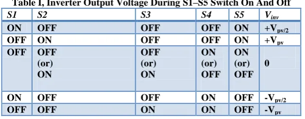
Vref2 will be compared with the carrier signal until it reaches zero. At this point onward, Vref1 takes over the comparison process until it exceeds Vcarrier. This will lead to a switching pattern for inverter switches (S1-S5). Switches S1–S3 will be switching at the rate of the carrier signal frequency, while S4 and S5 will operate at a frequency that is equivalent to the fundamental frequency. Table I illustrates the level of Vinv during S1–S5 switch on and off.
Table I, Inverter Output Voltage During S1–S5 Switch On And Off
S1 S2 S3 S4 S5 Vinv
ON OFF OFF OFF ON +Vpv/2
OFF ON OFF OFF ON +Vpv
OFF OFF
(or) ON
OFF (or) ON
ON (or) OFF
ON (or) OFF
0
ON OFF OFF ON OFF -Vpv/2
OFF OFF ON ON OFF -Vpv
IV.
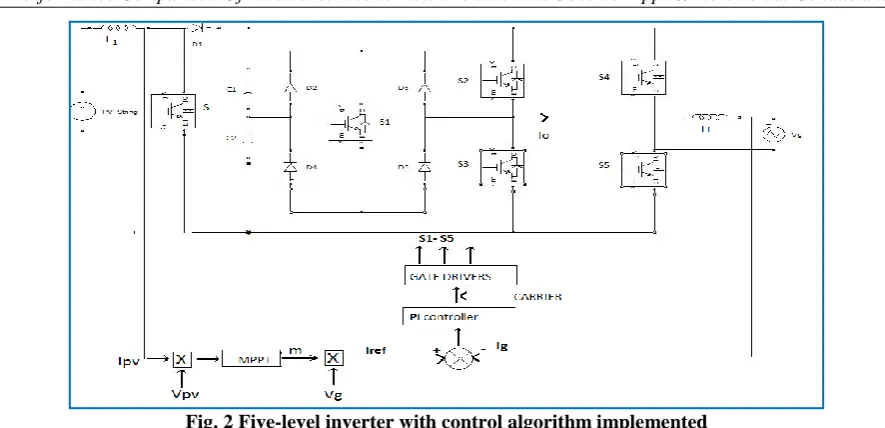
CONTROL SYSTEM ALGORITHM AND IMPLEMENTATION
Fig. 2 Five-level inverter with control algorithm implemented
The PI algorithm can be expressed in the continuous time domain as:- 𝑢 𝑡 = 𝑘𝑝 𝑒 𝑡 + 𝑘𝑖 𝑒 𝜏 𝑑𝜏
𝑡 0
Where e (t) error signal;
t is continuous-time-domain time variable; τ calculus variable of integration; 𝑘𝑝 proportional mode control gain.
Ki is the integral mode control gain.
Implementing this algorithm by using a DSP requires one to transform it into a discrete-time domain. Trapezoidal sum approximation is used to transform the integral term into a discrete-time domain because it is the most straightforward technique. The proportional term is directly used without approximation.
P term: 𝑘𝑝 e (t) =𝑘𝑝 e (k)
Iterm:
𝐾𝑖 𝑒 𝜏 𝑑𝜏 ≅ 𝐾𝑖
ℎ
2 𝑒 𝑖 + 𝑒 𝑖 − 1 .
𝑘
𝑖=0 𝑡
𝜏=0
Time relationship: t = k ∗ h, where h is the sampling period and k is the discrete-time index, with k = 0, 1, 2, ..
For simplification, it is convenient to define the new controller gain as:-
𝑘𝑖′ = 𝑘𝑖
ℎ 2
from which one can construct the discrete-time PI control law as
𝑢 𝑘 = 𝑘𝑝𝑒 𝑡 + 𝑘𝑖′ [𝑒 𝑘
𝑖=0
𝑖 + 𝑒(𝑖 − 1)]
To eliminate the need to calculate the full summation at each time step, the summation is expressed as a running sum sum (k) =sum (k − 1) + [e (k) + e(k − 1)]
u (k) =Kp e(k) +𝑘𝑖′sum(k)
These two equations, which represent the discrete-time PI control law, are implemented to control the overall operation of the inverter.
V.
MPPT ALGORITHM IMPLEMENTATION
Here we implement Perturb and observe (P&O) MPPT method and Incremental conductance MPPT method. In Perturb and observe (P&O) method the controller adjusts the voltage by a small amount from the array and measures power; if the power increases, further adjustments in that direction are tried until power no longer increases[5]. It is referred to as a hill climbing method, because it depends on the rise of the curve of power against voltage below the maximum power point, and the fall above that point. In the incremental conductance method, the controller measures incremental changes in array current and voltage to predict the effect of a voltage change. This method requires more computation in the controller, but can track changing conditions more rapidly than the perturb and observe method (P&O). The fig.3 and fig.4 explain the operation of Perturb and observe method and incremental conductance method with a flow chart.
Fig.3 Perturb and observe method Fig.4 Incremental conductance method
VI. SIMULATION MODEL
The simulation circuit for proposed single-phase five-level inverter topology with PI controller and MPPT algorithms is shown in Fig 5. The circuit is designed with three input PV strings with separate MPPTs and operating independently. The output of all the three MPPTs are summated using an adder and the net output is used as constant m to produce reference current Iref
VII.
SIMULATION RESULTS
Simulations were performed by using MATLAB and it also helps to confirm the PWM switching strategy. The Fig.6, show the switching pattern of the inverter switches obtained by simulation.Fig 7 and Fig .8 shows the simulated output of the circuits with perturb and observe method and incremental conductance MPPT method. The simulation results proves that the THD of five level inverter is reduced from 39% to 28% by replacing perturb and observe MPPT with incremental conductance MPPT, also the power factor and the shape of waveform is improved by implementing incremental conductance MPPT algorithm
Fig.6 Switching pattern of inverter switches (S1-S5)
Fig.7 simulated output voltage with Fig.8 Simulated output voltage with Perturb and observe MPPT Incremental conductance algorithm.
VIII.
CONCLUSION
This paper has presented a multilevel inverter topology for the feed back control of multilevel inverter for PV application. The configuration is suitable for PV application as the PV strings operate independently and later expansion is possible. A new PWM control scheme with two reference signals and a carrier signal has been used to generate the PWM switching signals. The feedback circuit utilizes a PI controller and MPPT algorithm such that desired ac output voltage can be obtained by controlling reference voltage Vg. The circuit topology, control algorithm, and operating principle of the proposed inverter with perturb and observe method and incremental conductance MPPT method have been analyzed in detail. Furthermore, the simulation results indicates that the THD of five-level inverter is reduced from 39% to 28% by replacing perturb and observe MPPT with incremental conductance MPPT, also the power factor and the shape of waveform is improved by implementing incremental conductance MPPT algorithm.
REFERENCES
[1]. Nasrudin A rahim ,Senior Members,IEEE” Multistring Five-Level Inverter With Novel PWM Control Scheme for PV Application .IEEE transactions on Industrial electronics, VOL. 57, NO. 6, JUNE 2010 [2]. Nasrudin A rahim ,Senior Members,IEE”Multi level inverter for grid connected PV system employing
digital PI controller” . IEE transactions on industrial electronics,vol 56,no. 1,january 2009
[3]. “L. M. Tolbert and T. G. Habetler, “Novel multilevel inverter carrier-based PWM method,” IEEE Trans. Ind. Appl., vol. 35, no. 5, pp. 1098–1107,Sep./Oct. 1999.
[4]. Text book on “power electronics “by PS Bhimbra.