The Study of Target Tracking Based on ARM
Embedded Platform
Lian Pan
School of Information Science and Engineering,Wuhan University of Science and Technology,Wuhan China E-mail: [email protected]
Xiaoming Liu
School of Information Science and Engineering,Wuhan University of Science and Technology,Wuhan China E-mail: [email protected]
Abstract—This article explored a solution of target tracking based on the ARM embedded platform, which gave a design and realization of removable image processing equipment to detect and track the pedestrian in the video. The integration level of embedded platform is very high, embedded platform supports real-time multitasking operating system, and comply with the requirements of real-time and miniaturization. Studying how to combine embedded platform with target tracking, it has instructional significance for robot development applications.
Index Terms—Embedded platform, Target tracking, ARM, Linux
I. INTRODUCTION
In recent years, with the requirements of modern society for military and civilian equipment constantly expanding and the demands continuously improving, the technology of moving target identification and tracking has rapidly developed a very important technology in modern information processing field, having a wide range of applications and development prospects. Target tracking has two outstanding characteristic: the amount of calculation data is very huge and the demand of processing speed is very high. The previous target tracking systems are most built with desktop PC and DSP processor, they can't very well meet the demands for real-time and miniaturization. It has higher demands for real-time in industrial (machine) visual inspection and video tracking supervisory control, that will be lead to failure of task if it can't meet the real-time. In an increasingly complex image application, it not only require hardware acceleration, but also require a real-time operation system support. The image processing application today are more and more compact system, which requires the target tracking system having high speed, highly integrated chip to complete the tasks originally needing many parts to cooperate. It requires the central processor can take many set of features at a suit, and through external expansion to realize the complex functions, to achieve the miniaturization of the system. In addition, the video image is characterized by a high capacity, for the real-time processing of large amounts of data, it doesn't only need high-speed CPU, also needs to
expand the storage capacity[1]. The appearance of the embedded processors represented by ARM makes the development of the embedded system which supports the large capacity FLASH and RAM memory, has the rich interface, supports the operating system with higher speed and higher integration, become future trend of the development of digital image processing system. The target tracking solution based on embedded platform has great potential for growth in future target tracking area.
Therefore, this paper explored a solution on target tracking based on ARM embedded platform, giving the design and implementation of a moving image processing equipment, to detect pedestrians in the video and track, analysing the embedded platform as a key issues for the target tracking solution, including the need for the ARM embedded platform, the system framework design, development process, and the choice for the embedded processor and operating system. The thesis on the basis of the overall design, completed system design and implementation, including hardware platform design, the completion of the Linux kernel custom, Bootloader, USB camera driver program development and the establish of OpenCV vision library, analysing the target tracking process finally. This paper also used self-adaption background subtraction to realize movement detection, extractd the characteristics of the pedestrian, realized moving target tracking using improved Mean-Shift algorithm.
II. THE WHOLE SYSTEM STRUCTURE DESIGN
The target tracking system uses a mobile image processing equipment to achieve the detection and tracking of the moving target in image. To make up for the deficiencies of the traditional target tracking system, and to achieve the requirements of real-time and miniaturization, in target tracking situations, because of the uncertainty of target tracking number, we need a multi-task implementation mechanism to solve these problems. Making use of the multitasking operating system, we just need to add new threads, can achieve the moving target tracking.
embedded platform is an effective way to solve real-time and miniaturization problems. The solution of target tracking system based on ARM embedded platform can satisfy the functional requirements.
The overall design which is based on the functional analysis, is the design of system framework, development
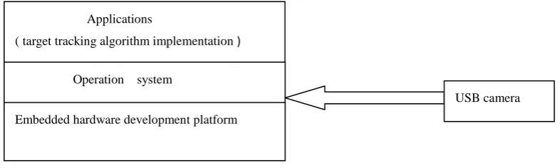
process and development principles. By and large, the embedded target tracking system based on ARM can be divided into four parts: camera, embedded hardware development platform, embedded operating system and the application program to achieve target tracking algorithm. As shown in Fig 1.
Figure 1. The structure block diagram of image processing system based on embedded platform
The main role of the camera is to capture video signals, then converts them into digital form to store. The hardware part took the embedded CPU of ARM kernel as core, also expanded the large capacious SDRAM memory. The ARM embedded hardware platform controls the acquisition and real-time processing of sequence images. Embedded operating system provides driver support, memory management, interrupt management and the task management of target tracking processing etc for the bottom hardware. It first starts operation system to accomplish the hardware initialization through the boot program starting after the system startup, and then through the operating system to achieve the calculation that target tracking needs and the distribution and recovery in real time of memory resources. Because of the support of operating system, the developers only need to focus on the realization of the software function in the application development, and don't pay attention to specific hardware details. If the operating system is the same, the application can be easily ported to other hardware environments. In the system, the application mainly achieves the algorithm that target tracking system needs, to ensure practicality of the target tracking system.
III. HARDWARE DEVELOPMENT PLATFORM DESIGN
In recent years, with the development of microelectronics technology, computer technology, communication as well as network technology, the embedded technology penetrates into various domains. Because the embedded object changes a lot, it leads to the diversification of embedded system and its applications that the requirements of embedded system itself on performance, system structure ect. aspects are various. As the embedded microprocessor based on the embedded system, it must deal with the challenges that the embedded faces in application, and ARM (Advanced RISC Machines) embedded microprocessor stands out in many kinds of embedded microcontroller processor with its complete series of architecture development of the system structure, tiny volume, low power consumption,
low cost, high performance, as well as the advantage of expanding function timely according to the different embedded objects. ARM is designed to achieve the structure of very small but high performance. It makes its kernel very small that the ARM processor structure is simple, so the consumption of devices is very low. The loading/storage system structure which adopted by the first designed ARM processor chip is a typacal reduced instruction set computer (RISC) structure. ARM architecture inherited the loading/storage system structure of RISC structure, fixed long 32-bit instructions and three-address instruction format. ARM processor extensively uses registers, the instruction execution speed much faster, most of the data operation completed in registers[6].
Since the target tracking system is researched by this paper, the operating system requires the ability of strong memory management, so we choose ARM kernel supporting the memory management unit MMU. Moving target tracking system requires to implement multi-process scheduling, so it is necessary to choose the right operation system to achieve this function. According to the real-time requirement of target tracking system, the processor having higher clock frequency of the system is needed. Based on the above three points, we adopt S3C2440 chip as the core processor in this paper.
This paper used the S3C2440 chip as the core processor. This processor has: supporting the memory management MMU, separate 16 KB instructions and 16 KB data caches, supporting the TFT LCD controller, NAND flash memory controller, 3-channel UATR, 4-channel the DMA, 4-channel PWM timer, I/O sports, RTC, 8-channel 10-bit ADC, IIC-BUS bus interface, IIS-BUS digital audio BUS interface, 2 USB host ports, l-port USB devices, SD/MMC card controller, 2-channel SPI. S3C2440 processor running at up to 533 MHz, it is the fastest kind of similar embedded CPUs, and has both low power consumption and high integration characteristics[2]. S3C2440 chip provides a set of of relatively complete peripheral which belongs to the general system, and makes the consume of the whole
Applications
( target tracking algorithm implementation )
Operation system
Embedded hardware development platform
system at the least. It is that because there is a lot of common function modules in the S3C2440 chip, we select it to eliminate the trouble of adding additional equipment configuration.
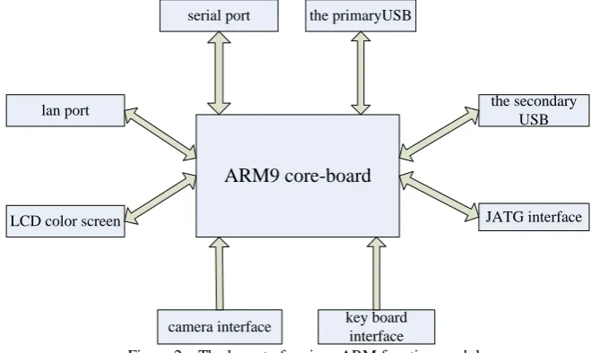
The hardware structure of the system is divided into two parts: the core module and the peripheral expansion
module. The core module mainly includes ARM microprocessor, memories (SDRAM, NAND Flash, Flash), crystals oscillator, reset, JTAG interface and I/O bus interface. The peripheral expansion modules include power supply, keyboard, LCD, serial and USB camera. The layout of each function module is shown in Fig 2.
ARM9 core-board
serial port the primaryUSB
lan port
LCD color screen
camera interface key board
interface
the secondary USB
JATG interface
Figure 2 The layout of various ARM function module
IV. THE SOFTWARE DESIGN OF SYSTEM
Embedded operating system is responsible for the allocation, scheduling, control, coordinating concurrent activities of all the software and hardware resources in embedded system. At present, embedded operating systems in the world have almost 200 kinds, in which some are real-time, also some are non-real-time. Linux is the operating system having open source which follows the GPL protocol, when it is used without paying license fee. The kernel can be arbitrarily cut, and the cutting is realized mainly through the method of reducing the space taken up by various code such as reducing the kernel, reducing the dynamic link library, reducing application and so on, as well as compressing the file system. It supports almost all the 32-bit CPU and 64-bit CPU. The hardware supported by kernel has various kinds, and the whole hardware driver programs can be almost found from the network. The Linux system supports almost all network protocols. There are a large number of available applications to use, from the compiler tools, debug tool to GUI programs, almost all of that have related versions under the GPL protocol. There is a huge community of developers, a large number of technical forums, and most problems can be solven fast and free .
Because Linux has many advantages such as open source, easy to transplant, abundant resources and free, in this paper we adopt Linux operating system, which not only improves the reliability of system and development efficiency, but also brings the multi-task potential of 32-bit CPU into full play. The configuration of Linux operating system includes three aspects of boot program, kernel and file system. Boot program is a program before the operating system running, which is used to complete to initialize the devices, sets up the map of memory space, prepares correct environment for the operating system
kernel. In this paper, Bootloader is used by the system to guide and load programs. The operating system uses the Linux2.6.13 kernel, and its development mode uses host developing mode, compiling kernel and application on the host, then downloading to the target platform through the network, debugging information via the Hyper Terminal. The file system is responsible for storing the configuration files of the system, and the peripherals driver programs of the system. After the completion of the operating system configuration, the main work is to program the drivers and applications. The driver program is a middle software layer between the application of the hardware, which accesses the device drivers also in the way of documents operation in Linux.
seting “V4L information in proc file system” as “Y”; backing to “Linux Kemel Configuration”, selecting “USB support”, seting “USB OV511 Camera support” as “Y”, then saving and exiting, recompiling the kernel. The ZC0301 camera driver uses the static loading way, its concrete steps are: in driver/usb/, decompress drive, then patching, and creating a new portfolio named spca5xx in
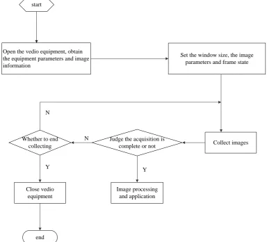
the current directory ; compile the kernel, selecting SPCA5XXX, then executing the commands of make dep, make zlmage, make modules, 3 .o files will be produced in the directory of /kemel/driver/usb/spca5xx; start the 3 .o files with a new kernel. Image acquisition flow chart is shown in Fig 3:
start
Open the vedio equipment, obtain the equipment parameters and image information
Set the window size, the image parameters and frame state
Collect images
Image processing and application Judge the acquisition is
complete or not Whether to end
collecting
Close vedio equipment
end N
Y
N
Y
Figure 3 The flow chart of image acquisition with USB camera In Video4Linux equipment device driver, it needs to
provide the implementation of the fundamental I/O operation interface functions such as open, read, write, close, the implementation of interrupt processing, and the implementation of memory mapping function as well as the control interface function ioct1 of I/O channels, and defines them in struct video_device. So when the application oprates system calls for device files such as open files, close, read, write and so on, Linux kernel will access the functions which are provided by driver program through the video_device structure. Most of the kernel code contain a large number of header files to get functions, data structure and the definitions of variables. There are several files that are special for the module, and they must appear in every module that can be loaded, almost all module code having the following contents:
#include<linux/module.h> #include<linux/init.h>
In the version of linux-2.6.13 kernel, it contains the required documents of device driver, such as the include/linux/videodev.h file, which defines the functions
and symbols required in Video4Linux device driver. The drivers/media/video/videodev.c file in the kernel provides a module of Video4Linux device driver for the kernel development, which provides some kernel interface symbols outwards for driver developers to add device drivers designed by themselves on the basis of this module. In the header file videodev.h, the data structure supported by Video4Linux is defined, as the following shown:
struct video_device {
struct device *dev; char name[32]; int type; int type2; int hardware; int minor;
struct file_operations *fops;
void (*release) (struct video_device *vfd); struct module *owner;
int users;
struct semaphore lock; char devfs_name[64]; struct class_device class_dev; };
V. TARGET TRACKING
A. Target Tracking Principle
input image
image preprocessing
image segmentation
feature extraction
Whether the target is true
target tracking
N
Y
Figure 4.1 Target tracking flow chart
It is the flow chart of moving target tracking as Fig 4.1 shown, and the target capture process includs image input, image preprocessing, moving target detection, moving object extraction, moving object tracking process, etc. The input of image is that obtaining images, it recognizes, captures and follows up the target. The pretreatment of image refers to dealing with the input target image of system, geting rid of the noise and interference points of original images. Feature selection refers to a process of selecting the represented the characteristic of target information from the separated targets, and its purpose is to obtain the objective independent, identifiable characteristics. Feature extraction is the calculation of the selected characteristics quantity, matching and contrasting these parameters after the job of successfully extracting target characteristics, and seting the credibility mechanism to determine the authenticity of the target[3].
B. The Input of the Target Image and Image Preprocessing
This paper uses a USB camera with ZC0301 microchip to capture images. As in the imaging process, there are various external interference factors, and the influence of the surrounding environment, resulting in poor image quality, therefore it is necessary to appropriately deal with these images. After pretreatment, the output image quality gets a degree of improvement, in here image preprocessing technology we used includes transformation of grey scale, noise filtering, etc.
Using gray scale images without color information,
namely in figure each pixel consists of only one byte of eight-bits showing the pixel luminance values, so gray scale image possesses 256 gray levels, the computational cost which is to dealed with is decreased, convenient for the subsequent processing[5].
The transformation from ture color image to gray image:
RGB—>Gray:Y=0.299R+0.587G+0.12 (5.1) Where Y is gray image gray value, R, G, and B are respectively true color image of red, green, blue three-channel color values. According to the equation
(5.1), color images can be transformed into gray-scale images.
Filters can be classified into two categories in general: spatial domain filters and frequency domain filters. Spatial domain filters generally use the smooth filtering and median filtering, and in frequency domain, generally using the low-pass filter. The image preprocessing used median filtering in this paper. The basic principle of median filtering is to use mid-value of each point in the adjacent domain of one point which belongs to digital image or digital series to instead of the value of the point ( if there are even pixels in the window, then take the average of two intermediate values )[4]. The median filtering generally uses a sliding window containing odd number of points. The specific means is to make sure a window of odd number of pixels first, after that each pixel in the window lines up according to grayscale, using grey value of the position to replace the original
) , (x y
f grayscale value to be enhanced image
g
(
x
,
y
)
,namely
f x k y k w
Mediany x
g( , ) ( , 1),( ,1) (5.2)
w
is the selected window size.Generally speaking, it is more effective for the two-dimensional median filtering to restrain noise than one-dimensional median filtering. Different image contents and different application requirements need to choose different window shapes and sizes. The results of median filtering experiment are shown in Fig 4.2 (a), (b).
(b) after the median filtering Figure 4.2 Images of the median filtering
In Fig 4.2, it can be seen that the Fig 4.2 (a) has various noises because of being disturbed. The median filter. Fig 4.2 (b) changes to be smooth and clear after median filtering.
C. Moving Target Detection
The purpose of motion detection is to segment the variational region out of the background from sequence images. This paper researches how to extract the moving object in the case of static background, and the change of light is relatively small in experimental environment, so the background subtraction method is used to extract the moving target.
This paper used the feature matching method for background extraction. First is to determine the characteristics information of images, which are generally concentrated in the place of pixel value changing more vigorously, that is the image edge regions. It can make the image edges become more prominent to calculate the gradient of image. This paper used the Sobel operator to calculate the gradient.
The basic idea of sobel operator is that: with the image to be enhanced any pixels at the center, intercept a 3
3 pixel window, as shown below. Calculate respectivelygradient of the pixels in
x
,
y
directions in the window center. ) 1 , 1 ( ) , 1 ( ) 1 _ , 1 ( ) 1 , ( ) , ( ) 1 , ( ) 1 , 1 ( ) , 1 ( ) 1 , 1 ( j i f j i f j i f j i f j i f j i f j i f j i f j i fSobel operator can also be represented in the vector way. The pixels in the window can be expressed as a 3
3 two-dimensional vector. Sobel operator can be decomposed into the following two templates:
1
0
1
2
0
2
1
0
1
1M
1
2
1
0
0
0
1
2
1
2M
We take the area where the pixels total number is the
maximal as a characteristic region, because such pixel values of the characteristic region change obviously , it is
easier to match, contributing to reducing errors. It is imperative to match the image and the second image after obtaining an image of the characteristic region. After determining the background, the next step is to use background subtraction method to segment threshold to extract the moving target.
Comparing the differences of pixels corresponding to the current image and the background image, if the difference value is greater than a certain threshold, then determine the pixels to be pixels which compose the moving target. The amounts that can be used to compare are color, brightness and grayscale, etc, the paper adopts gray value subtraction, testing rules are as follows:
TH
y
x
B
y
x
I
TH
y
x
B
y
x
I
y
x
M
|
)
,
(
)
,
(
|
,
1
|
)
,
(
)
,
(
|
,
0
)
,
(
Where,
(
x
,
y
)
represents pixel coordinates, I(x,y)represents grayscale value of the current image pixel,
) , (x y
B represents the gray value of the pixel in corresponding position in background image, TH is the threshold. The final result is a binary image.
In order to eliminate the influence of noise and background disturbances, this paper used closing operation to the results after detection, and got the full zone of the moving target, then calculating the size of each independent prospect area (that containing the pixels number), geting the exact movement area, and the pixel value was M(x,y). Finally, M(x,y) will be covered on the original image, the corresponding pixel points that values are 1 are the moving targets pixel points.
VI. MEAN-SHIFT ALGORITHM
the whole, overcome the problems of target deformation and rotation well, without doing exhaustive search, rapidly converge to the best candidate position, but the disadvantage is that it is hard to identify the correct target, when the target and background gray value distribution is similar.
Mean-Shift algorithm[5] is a kind search algorithm of local optimal calculation, calculating similarity probability density distribution between candidate target and target module, obtaining the best path of matching search by using the probability density gradient descent method, accelerating the moving target position, reducing the search time. In this paper the design target tracking system using Mean-Shift algorithm.
Mean-Shift algorithm starts with the kernel density estimation algorithm (also called Parzen windows estimate), given in d dimension space of having n sample datas
i
x , i1...n, , the kernel estimation of multi-dimensional variable can be written as:
2 1 2 / 1 , ^ , ( ) | | H x x k H nh c xf n i
i d d k k h
Where,
c
k,d is the normalization constant;k
(
x
)
is called (kenal) function nuclear or contour (profile) function;H
is thed
d
dimension bandwidth matrix. Complete representation of parameterH
can increase the complexity of the algorithm, in practice, weoften use diagonal matrix
H
diag
[
h
12...
h
d2]
orh
I
2
,
I
is thed
d
unit matrix. For simpleness, we use the latter representation, then the kernel density estimation can be written as:
2 1 , ^ ,(
)
h
x
x
k
nh
c
x
f
i n i d d k kh (6.1)
Among them, the kernel function
k
(
x
)
must satisfy the following conditions:1)
k
(
x
)
is non-negative;2)
k
(
x
)
monotonically decrease from the center to the outward, such as, if0
a
b
, then)
(
)
(
a
k
b
k
;3)
k
(
x
)
is bounded. Whenk
(
x
)
is differentiable, the gradient can be obtained from equation (6.1)
2 1 2 , ^ ,(
)
2
)
(
h
x
x
k
x
x
nh
c
x
f
i n i i d d k kh (6.2)
Define
g
(
x
)
k
(
x
)
, we can get from the above equation:
x h x x g h x x g x h x x g nh c h x x k x x nh c x f i n i i n i i i n i d d k i n i i d d k k h 2 1 2 1 2 1 2 , 2 1 2 , ^ , 2 ) ( 2 ) (Where, the second part is the Mean-Shift algorithm, set
x
h
x
x
g
h
x
x
g
x
x
m
i n i i n i i g k
2 1 2 1 ,(
)
2 1 , ^ ,(
)
h
x
x
g
nh
c
x
f
i n i d d k gh (6.3)
Among them,
c
g,d is the normalization constant,then the above equation can be written as:
(
)
(
)
2
,(
)
, 2 , ^ , ^
,
m
x
c
h
c
x
f
x
f
hgd g d k g h k
h
Then there is:
)
(
)
(
2
1
)
(
^ , ^ , 2 ,x
f
x
f
c
h
x
m
g h k h g h
Among them,
c
c
g,d/
c
k,d . The above equation explains that local mean values move toward the near data sample dense regions, so there is the iterative formula:
y
t1
y
t
m
h,g(
y
t)
Where
y
t is on behalf of the stept
of the sample data,y
t1 represents the step t1 of sample data, we can obtain the iterative formula of Mean-Shift algorithm through substitution and simplification :t t t
t
y
d
y
1
(6.4)Where, /2 ( ) 0
^
,
2
t h c fhg yt ;
(
)
^
,k t h
t
f
y
d
.It is shown that Mean-Shift algorithm along gradient direction iteration makes each point to be handled “moves” to the local maximum points of probability density function, the step
t
changes adaptively with the iterative process, namely when the current data relatively belongs to low density, the iteration step is bigger; near the local maximum value, the iteration step is smaller.
Mean-Shift algorithm convergence conditions are very relaxed, as long as making sure the tracking target, the whole tracking process don’t need additional parameters input.
estimation
(
)
^,
x
f
hk grow, having excellent stability.Since it is unnecessary to estimate the density distribution
)
(
^
,
x
f
hk , we can search the local maximum directly along gradient direction, greatly reducing the computational complexity, so this algorithm has good real-time, and based on the Mean-Shift optimization algorithm representing the development level of video tracking algorithm, the algorithm get the computer vision industry wide concern.The above algorithm in Linux system used OpenCV, in the Windows system did simulation experiments with Matlab. In the actual target tracking, we use Gaussian kernel as the kernel function.
Gaussian contour function is:
) 0
2 1 exp( )
(x x x
kN (6.5) The corresponding kernel functions is:
0 )
|| || 2 1 exp( )
2 ( )
( /2 2
x x
x
K d
N (6.6)
Fig 5.1 is the function and its kernel function according to the above description:
Figure 5.1 Gaussian contour function and its kernel function
We can see that the kernel function for the center pixels of the template has greater weights, as close to the edge of template, the weights are lower. Using a group of pedestrians movement video sequence images, we frame manually select a size of 30 ×80 template in the first:
Figure 5.2 The target template
Using kernel density estimation to describe it, to make calculation simply, and using 16 segment histogram in the simulation experiments, using Gaussian kernel function to weight, we can conclude the kernel density:
q
ˆ
=[0.1569,0.0541,0.0156,0.0121,0.0021,0,0,0,0,0.0613,0.0692,0.0313,0.0157,0.0287, 0.0484,0.3931];
Figure 5.3 The rendering pictures of system tracking the pedestrian The analysis of experimental results shows that:
(1) the resources allocation of ARM hardware development platform that the system choosed is reasonable, it can complete the complicated target tracking algorithm in the stipulated time.
(2) the target tracking algorithm used by system can correctly recognize moving targets, more stably under the ARM development platform.
(3) after optimizing the whole system software, the processing time can be controlled in 100 ms when ARM dealed with algorithm, meet the real-time requirement of system.
VII. THE CONCLUSION
The target tracking solution based on the ARM embedded platform suggested by this paper, gives a mobile image processing equipment design and realization.
On the basis of the overall design, this paper completed the design and implementation of the system, including the system framework and the design of hardware platform, development process, for the selection of embedded processor and operating system, analyzed the process of target tracking. It realized the movement detection with the adaptive background deduction method, extracted the characteristics of pedestrian, realizing the moving target tracking by using Mean-Shift algorithm. This equipment that has been extended can be applied to the traffic flow statistics and property safety application. The potential application is very enormous, awaiting further research and exploration.
REFERENCES
[1] Kenan Teng. Air missile anti-missile combat effectiveness of the comprehensive assessment method[J]. Missiles and Guidance Journal, 2003.12 (2) : 26-28 1991,24(7): 661-673
[2] USER’S MANUAL S3C2440X 32-Bit RISC
Microprocessor. Samsung Electronics
http://www.samsung.com
[3] Tiegen Liu. Embedded Images Detection Technology [M]. Beijing: Mechanical Industry Press, 2008
[4] Wang Hu, Zhishu Li, Qi Huang. The Denoising Method Based on The Rough Set and Multi- differential Image. Small Miniature Computer Systems, 2006, 27 (12) : 2341-2345
[5] Dapeng Ding, Huan Huang etc. Real-time Movement Target Tracking Based on the Mean-Shift Algorithm [J]. Shanxi Electronic Technology, 2008, 36:42-44
[6] Cumain A, Guiducci A, Grattoni P. Image description of dynamic scenes[J]. Pattern Recognition,
[7] l.Kawakami, Ynimura, K.Hamada.Real-time Extension for WindowsNT/CE Used for Control Systems. Proeeedings of the 39th SICE Annual Conference. USA, 2000, USA: SICE, 2000, 319-324
[8] Cumain A, Guiducci A, Grattoni P. Image description of dynamic scenes[J]. Pattern Recognition, 1991,24(7): 661-673
[9] John C. Reynolds. An Overview of Separation Logic[J], Lecture Notes in Computer Science, Springer Berlin or Heidelberg, 2008, 4171:460-469
[10] Andreas Opelt, Axel Pinz and Andrew Zisserman. Learning an Alphabet of Shape and Apperance for Multi-Class Object Detection[J]. International Journal of Computer Vision,2008,80(1):16-44
Lian Pan (1964-): a professor of College of Information Science and Engineering ,Wuhan University of Science and Technology, Wuhan, p.r. China, mainly studied on intelligence test and automatic device.
Xiaoming Liu (1985-): a master of School of Information Science and Engineering, Wuhan University of Science and Technology, Wuhan,
pr.China, mainly studied on