Space Exploration Rover Using LABVIEW
P. Thirumurugan S. Arunrajan
Assistant Professor U.G. Student
Department of Instrumentation and Control Engineering Department of Instrumentation and Control Engineering Saranathan college of Engineering, Tiruchirappalli, India Saranathan college of Engineering, Tiruchirappalli, India
S. Nagaarjun K. Prakash
U.G. Student U.G. Student
Department of Instrumentation and Control Engineering Department of Instrumentation and Control Engineering Saranathan college of Engineering, Tiruchirappalli, India Saranathan college of Engineering, Tiruchirappalli, India
R. Sivamanikandan U.G. Student
Department of Instrumentation and Control Engineering Saranathan college of Engineering, Tiruchirappalli, India
Abstract
In this paper with the reference of NASA’s MARS Curiosity Rover, this project is meant for a low cost, lightweight and small size unmanned ground vehicle (UGV) which is controlled by NI-myRIO a hardware component of National Instruments can be used for surveying and determining the natural conditions for living beings like identification of gases, collection of picture samples etc., It consists of six individual motors with lightweight chassis for achieving various movements of rover, gas sensors, camera with servos, long-lasting power supply with its required communication tools. The Six wheeled Rover with three or more suspension alignments will move and collect various samples for identification of gases and taking pictures around the astronomical areas automatically by the automated movements.
Keywords: Rover, Camera, Lab View, Gas Sensor, Arm
_______________________________________________________________________________________________________
I. INTRODUCTION
A rover is an unmanned ground vehicle that can explore surface of various astronomical bodies like mars and moon. Rover stands for remotely operated video enhanced receiver. They usually arrive at the planetary surface on a launder-style spacecraft used to find out information by collecting dust, rocks and take pictures. Rovers have to withstand high levels of acceleration, high and low temperatures, pressure, dust, corrosion, cosmic rays, remaining functional without repair for a needed period of time.
Due to overpopulation and over exploitation this is right time to think for the alternate place to start the human race. For this purpose, human have to search for the chance of living in other celestial bodies rather than that of earth. In search of that , various nations in the earth have sent many orbital satellites. But it will not provide enough details to start a new life form. So, they decided to go in search for the trace of indeed things for a human life such as water, soil form and gases like oxygen, nitrogen, and carbon-dioxide. In result, various rovers emerged. They will send safely to other planets by high end landers. With the Spacecraft, Landers will be incorporated in order to make the rover to touch the ground smooth and gently. Landers have inbuilt heat shield to withstand the heat when it enters the other celestial bodies atmosphere. At First it will enter the body with the body’s gravitational pull and later it will propel up to reduce the speed to land on the ground. To know the distance between ground and the rover, rovers have radar connections. But, it will work after the heat shield separates. After all these process, the rover will touch down the surface without any damage. Sojourner, the Mars Pathfinder rover, discovered pebbles on the surface and in rocks that may be sedimentary not volcanic in origin. Surface pebbles may have been rounded by Ares flood waters or liberated by weathering of sedimentary rocks called conglomerates. Conglomerates imply that water existed elsewhere and earlier than the area flood. Most soil-like deposits are similar to moderately dense soils on Earth. Small amounts of dust are currently settling from the atmosphere [1].
The rock nest Aeolian deposit is similar to Aeolian features analyzed by the Mars Exploration Rovers (MER) spirit and opportunity. The fraction of sand <150 μm in size contains ~55% crystalline material consistent with a basaltic heritage, and ~45% x-ray amorphous material. The amorphous component of rocknest is fe-rich and si-poor, and is the host of the volatiles (H2O, O2, SO2, CO2, and Cl) detected by the Surface Analysis at Mars (SAM) instrument and of the fine-grained nanophase oxide (npox) component first described from basaltic soils analyzed by MER. The similarity between soils andaeolian materials analyzed at Gusev crater, MeridianiPlanum and Gale crater implieslocally sourced, globally similar basaltic materials or globally and regionally sourced basaltic components deposited locally at all three locations [2].
thermal batteries on the back shell and rechargeable batteries on the rovers. Significant among them are the Li ion rechargeable batteries, which are being utilized for the first time in a major NASA mission. The selection of the Li ion battery has been dictated by various factors, including mass and volume constraints, cycle life, and its ability to operate well at sub-zero temperatures down to -30°c, at moderate rates. This paper describes the selection criteria, design and performance of the three battery systems on 2003 MER mission [4]
The recently approved ExoMars rover is the first element of the ESA aurora programmed and is slated deliver the Pasteur exobiology payload to Mars by 2013. The 0.7 kg panoramic camera will provide multispectral stereo images with 65° field-of-view 1.1 milliradian/pixel and high resolution 85 micro rad/pixel monoscopic “zoom” images with 5° field-of-field-of-view. The stereo Wide Angle Camera (WAC) is based on beagle 2 stereo camera system heritage. The Panoramic camera instrument is designed to fulfill the digital terrain mapping requirements of the mission as well as providing multispectral geological imaging, color and stereo panoramic images and water vapour abundance and dust optical depth measurements. It can also be used for high resolution imaging of inaccessible locations on crater walls and to observe retrieved subsurface samples before ingestion into the rest of the Pasteur payload [5]
II. BLOCK DIAGRAM
Fig. 1: Block Diagram of Rover
Fig.1 shows the block diagram, it consists of 3 modules that are display module, gas sensing module, wheels configuration. Here the NI-myRIO is used as the interfacing component between computer and rover .Since the myRIO get supply through battery. The Arm servo motors used to pick the samples on their way and wheel motors is to move the rover. Then the driver circuit is available for the movement of motors. The gas sensor mq-135 is used to detect presence of atmospheric gas for the survival of living things in that place, which will now detect only the presence of CO2 .The image captured from camera will be acquired by personal computer through TV card .This Rover can be switched over between auto mode and as well as manual mode.
NImyRIO
Fig. 2: myRIO
The fig 2 shows the NI myRIO kit which is the basic interfacing system of our work. The LABVIEW programming has been programmed into the NI myRIO kit. The NI myRIO kit consists of wireless module which is inbuilt in it. It also consists of inbuilt accelerometer by which the linear motion of the rover can be determined. Some features of the NI myRIO kit has been listed below. Affordable tool to teach and implement multiple design concepts with one device.
10 analog inputs, 6 analog outputs, 40 digital I/O lines. Wireless, LEDs push button, accelerometer onboard.
Xilinx FPGA and dual-core ARM Cortex-A9 Zynq processor.
Programmable with Lab VIEW or C; adaptable for different programming levels.
Motor Driver IC L293D
L293D is a typical motor driver or motor driver IC which allows DC motor to drive on either direction. L293D is a 16 Pin IC which can control a set of two DC motors simultaneously in any direction. It means that you can control two DC motors with a single L293D IC. Dual H-bridge motor driver integrated circuit (IC). The L293D can drive small and quite big motors as well. It works on the concept of H-bridge. H-bridge is a circuit which allows the voltage to be flown in either direction. As you know voltage need to change its direction for being able to rotate the motor in clockwise or anticlockwise direction. Hence, H-bridge IC is idle for driving a DC motors. In a single L293D chip, there are two H-bridge circuits inside the IC which can rotate two DC motors independently. Due to its size it is very much used in robotic applications for controlling DC motors.
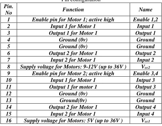
Pin Diagram Description
The table.1 shows the basic pin diagram for the motor driver circuit. The driver circuit used here is L293D IC, we use of 16 pins in configuration, the 16 pins are input pin, output pin, ground and power supply.
Table – 1 Pin configuration
Pin.
No Function Name
1 Enable pin for Motor 1; active high Enable 1,2 2 Input 1 for Motor 1 Input 1 3 Output 1 for Motor 1 Output 1
4 Ground (0v) Ground
5 Ground (0v) Ground
6 Output 2 for Motor 1 Output 2 7 Input 2 for Motor 1 Input 2 8 Supply voltage for Motors: 9-12V (up to 36V ) Vcc2
9 Enable pin for Motor 2; active high Enable 3,4 10 Input 1 for Motor 1 Intput 3 11 Output 1 for motor 1 Output 3
12 Ground (0v) Ground
13 Ground(0v) Ground
14 Output 2 for Motor 1 Output 4 15 Input 2 for Motor 1 Input 4 16 Supply voltage for Motors: 5V (up to 36V ) Vcc1
DC Gear Motor
Wireless Camera Module
Wireless security cameras transmitter a video and audio signal to a wireless receiver through a radio band. Analog wireless is the transmission of audio and video signals using radio frequencies. Typically, analog wireless has a transmission range of around 300 feet (91 meters) in open space; walls, doors, and furniture will reduce this range. Analog wireless is found in three frequencies: 900 MHz, 2.4 GHz, and 5.8 GHz frequency. Most household routers, cordless phones, video games controllers, and microwaves operate on the 2.4GHz frequency and may cause interference with your wireless security camera. 900 MHz is known as Wi-Fi friendly because it will not interfere with the internet signal of your wireless network.
Gas Sensor
Gas Sensor applies SnO2 which has a lower conductivity in the clear air as a gas-sensing material. In an atmosphere where there may be CO2 gas, the conductivity of the gas sensor raises along with the concentration of the CO2 gas increases. It performs a good detection to smoke and other harmful gas, especially sensitive to ammonia, sulfide and benzene steam. Its ability to detect various harmful gas and lower cost make MQ-135 an ideal choice of different applications of gas detection.
Lab View
Laboratory virtual instrument engineering workbench is a system design platform and development environment for a visual programming language from National Instruments. The graphical language is named “G” (not to be confused with G-code). Originally released for the apple Macintosh in 1986, LABVIEW is commonly used for the data acquisition, instrument control & industrial automation on a variety of platforms including Microsoft windows, various versions of Unix, Linux and OS -X. The latest version of LABVIEW is LABVIEW - 2017 is released in May 2017.
Data Flow Programming
The programming paradigm used in LABVIEW, sometimes called G, is based on data availability. If there is enough data available to a subVI or function that subVI or function will execute. Execution flow is determined by the structure of a graphical block diagram (the LABVIEW -source code) on which the programmer connects different function-nodes by drawing wires. These wires propagate variables and any node can execute as soon as all its input data become available. Since this might be the case for multiple nodes simultaneously, LABVIEW can execute inherently in parallel. Multiprocessing and multi-threading hardware is exploited automatically by the built-in scheduler, which multiplexes multiple OS threads over the nodes ready for execution.
Interfacing to Devices
LABVIEW includes extensive support for interfacing to devices, instruments, camera, and other devices. Users interface to hardware by either writing direct bus commands (USB, GPIB, and Serial) or using high-level, device-specific, drivers that provide native LABVIEW function nodes for controlling the device.
LABVIEW includes built-in support for NI hardware platforms such as Compact DAQ and Compact RIO, with a large number of device-specific blocks for such hardware, the Measurement and automation explorer (MAX) and virtual instrument software architecture (VISA) toolsets.
III. DESIGN & SIMULATION
Fig. 3: Over All Setup of the Rover
The fig 3 shows the overall view of our rover system. The rover basically consists of hardware components like wheels, suspension system, myRIO camera and gas sensor and driver circuit. The suspension has been used in order to avoid obstacles of up to 15cm height. The geared motor used here will be of high torque and low speed. The motor used here is DC geared motor of 15v.
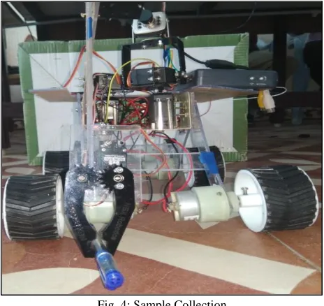
Fig. 4: Sample Collection
In the above fig 4 the rover consists of gripper been system by which the sample can be picked up by the gripper. The gripper is been controlled by the LABVIEW program. The gripper has been programmed and the object is been picked up with the help of gripper.
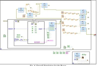
Fig. 6: Overall Simulation for the Rover
The fig6 shows the overall program for the Rover as well as the simulation for the gas sensor. In this program initially the motor control has been programmed. The motor consists of four directions they are forward, backward, left and right turn mechanism. The motor can be controlled by two methods they are manual mode and auto mode. The manual mode will be of remote controlling mechanism. The auto mode will not require any manual control instead they will be automatically control the directions. The gas sensor has been used here in order to sense the CO2 gas, LPG gas, etc. The gas sensors will consists of analogue input and also digital input, the while loop and case structure has used in the simulation. When the while loop gets ON, the program will go to the first case structure. There are two case structure available here, one is used for auto control second one is used for manual control. The servo motor angle will get changed when the accelerometer of the myRIO gets changed. There are four servomotors which have been used for the arm mechanism. The four mechanisms are body, shoulder, elbow and gripper. The four servo motors are used in the manual control. The gripper is used for the sample collection.
IV. RESULT & ANALYSIS
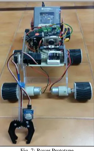
Fig. 7: Rover Prototype
The fig 7 shows the overall prototype of the rover system. The ideas of controlled surveillance robot have been successfully implemented. The robot has a wireless camera for surveillance purpose. The main idea behind the development of this project is to build a robot which will help many aspects. This kind of rover for surveillance proves to be cost efficient as it uses only Wi-Fi modules and driver circuits. The image processing is done remotely on Ni-LABVIEW environment. LABVIEW offers high-level image processing applications. The scope for the future developments is literally limitless.
V. CONCLUSION
In this paper, the components and working of the rover is explained. That is the movement of arm and wheel of rover is controlled using Lab VIEW. The rover connected with a rechargeable Li-Po battery. So, the distance coverage of rover will be increased .hence the concept of rover with high end suspension to be extended over for the purpose of surveillance in man-made disasters area, on board energy source, such as a radioactive module for enormous energy source, with high end camera, it can make an immaculate click of pictures of natures in various inaccessible areas and the Arm, will support the bomb squad for detection and disposal of intelligent bombs in an unmanned nature. It will reduce the cost of human life. The above plans will be implemented as a real time .this will be developed in our near future.
REFERENCES
[1] Rover Team “Characterization of the martian surface deposits by the mars pathfinder rover, sojournel” science, vol. 278, 5 December 1997 [2] D. F. Blake1 “Curiosity at gale crater, mars: characterization and analysis of the rocknest sand shadow”Science, vol 341, 27 September 2013
[3] Wing-HuenIp, Jun Yan, Chun-Lai Li2 and Zi-Yuan Ouyang “The chang’e-3 lander and rover mission to the moon55” research in astronomy and astrophysics, vol. 14, pp. 12, 2014
[4] B. V. Ratnakumar, M. C. Smart, A. Kindler, H. Frank, R. Ewe and S. Surampudi Jet Propulsion Laboratory, California Institute Of Technology, Pasadena “Lithium batteries for aerospace applications: 2003 mars exploration rover” ,journal of power sourcesvolumes 119–121, pp. 4, 1 June 2003.
[5] Andrew D. Griffiths, Andrew J. Coates, Ralf Jaumann, HaraldMichaelis,GerhardPaar, David Barnes, Jean-Luc Josset and The Pancam Team “Context for the esaexomars rover: the panoramic camera instrument” International journal of astrobiology,vol 5,issue 3, pp 269-275, July 2006.
[6] Kaichang Di A , FengliangXu A , Jue Wang A , SanchitAgarwal A , EvgeniaBrodyagina A , Rongxing Li A, Larry Matthies B “Photogrammetric processing of rover imagery of the 2003 mars exploration rover mission” journal of photogrammetry &remote sensing, vol. 63, pg no.181–201, 2008
[7] Bharathi. G1, Phanindra Reddy, M.Tech Iv Sem, Dept Of Ece, Rymec Bellary Associate Professor, Dept Of Ece, Rymec Bellary “Design and development of an intelligent dynamic path finding/survivallence automated guided vehicle using ni-myrio” international Journal of Research in Engineering and Technology ,volume: 04 ,Special Issue: 05 , May-2015.
[8] AshiteyTrebi-Ollennu, P. Chris Leger, Eric T. Baumgartner and Robert G. Bonitz “ Robotic arm in-situ operations for the mars exploration rovers osurface mission” systems, man and cybernetics, vol-12, 12 October. 2005
[9] K. Mohamed Hussain, R. AllwynRajendranZepherin, M. Shantha Kumar, Ug Student, S. Abirami, Assistant Professor, Department Of Instrumentation And Control Engineering, Saranathan College Of Engineering Trichy. “Control and interfacing of motors with ni-labvioew using ni-myrio” international journal for innovaoti[ve research in science & technology, volume o1 , issue 8 , January 2015
[10] Daniel M. Helmick, Yang Cheng, Daniel S. Clouse, Max Bajracharya, and Larry H. MatthiesStergiosI. Roumeliotis “Slip compensation for a mars rover” ieeeintelligent robots and systems, 2005. 2005 international conference on 2-6 August. 2005.