ISSN (Online): 2320-9364, ISSN (Print): 2320-9356
www.ijres.org Volume 4 Issue 5 ǁ May. 2016 ǁ PP.48-53
In Application Programming Based on CCP
Fang Hongqing
1, Lu Junwei
2, Xiong Mengrong
3(College Of Automotive Engineering, Shanghai University Of Engineering Science, Shanghai 201620, China)
Abstract: For the difficulties of auto-body ECU’s software upgrade, a method of ECU’s upgrade based on
CCPand CAN bus is presented afterillustrating the principle of In Application Programming(IAP) technology.
Besides, the implementation on the XC167CI is given in the paper. Theprocessing method of load file in theload
tool and the implementation method of bootloader are expounded. Experimental result shows that thesystem not
only achieves the function of application code upgrade but also runs stably.
Key words: upgrade; In Application Programming(IAP); CAN Calibration Protocol(CCP)
I.
OUTLINE
In the process of traditional embedded software development,application code is downloaded into the
RAM or Flashthrough the debug interface (BDM, JTAG and NECS) download in the debugging stage.In the
laterperiod of development stage ,the debug interface is removed.To add new control algorithm or new features,
we must use a special programmer to write new code into the ECU program storage.In the car body control
system, more and more new control algorithms, new featuresturn up.It’s not only trouble but also easy to
damage the circuit board while we frequently plug the memory. So developing a bootstrap loading function of
online upgrade system is necessary.With the emergence of IAP technology and the drop of flash prices , the
ECU generally has IAP (In Application Programming) function and large flash memory storage space, which
provides the necessary conditions for the online software update feature.
Now there are many different kinds of online upgrade scheme based on IAP technology ,each of which
adapts different fields.The literature [1] using RS232 bus and the YMODEM associationdevelop a intelligent
terminal upgradesystem. Literature [2] put forwards a user program online programming methodfor robot
development platform. Literature [3]achieves the ECU upgrade systemsuitable for cars through Line bus,the
scalability of which is not well,for it uses custom protocol. The CCP (CAN Calibration Protocol) protocol is a
kind of calibrationprotocol based on CAN bus.It has many advantages ,such as reliability,fast transmission speed
and good generality.Therefore, design an online upgrade system based on CCP protocol won’t need to add other
hardware resources and can meet the actual demand,which has certainpractical significance.
II.
IAP AND BOOTLOADER PRINCIPLE
In order to achieve the IAP functions, that is, when running the application ,the code can update by its
own,Accordingly,it is needed to add the bootloadercodeinto the firmware part to realizing the function.The Flash
memory is divided into two storage area in structure, one area stores bootloader code, the other stores
application code.In the process of normal work, the system is running in the application code, while it jumps
into bootloader areawhen receiving update command. Later,it downloads the application code by
communication bus (CAN, serial port, etc.) and writes the code into application code area. After finishing
Ⅲ. DESIGN THE ONLINE UPGRADING SYSTEM
Online upgrading system hardware structure is mainly composed of three parts, PC which has
installthebootloaderdownload tools, USB-CAN interface card, internal installed bootloader ECU.PC provides
the user operation interface and download access of application code. As there is no reserved CAN interface in
PC, so we need to communicate PC with ECUthrough the USB-CAN interface card.The software mainly
includes two parts: the master bootloader unit in PC and the slave bootloader unit in ECU.
3.1 Ccp Protocol And Bootloader Download Tool
CCP protocol is a protocol based on master-slave communication mode. The master and slave build
logical connection according to setting the address.Master send CRO(Command Receive Object) to control the
data stream after the connection is established. The slave executes the command from the master and then
returns a DTO(Data Transmission Object),containing response information. Six CCP commands are used in the
onlineupgradetool:Connect,Set_Mta,Program,Disconnect, Clear_Memory,Build_Chksum. Those Commandsare
Designed according to the CCP protocol standard.
To figure out the specific format of command messages and reply messages, see CCP protocol specification.
The XC167CI target code is HEX386 file.The file is a ASCII text files,each row of which contains a
complete record.Each record indicate the machine code or constant data which are recorded in hexadecimal.
Record format is as follows:
:llaaaatt[dd....]cc
Among them, the colon is the start of each record; ll is the data-length field, showing the number of
bytes in data field(dd....); aaaa is the address field, indicating the starting address of the record in ECU memory;
tt is the record form;all the forms are as follows:
00: data record
01: file end record
02: extended segment address record
04: extended linear address record
dd is data field,representing a byte of data. A record may have multiple bytes of data, the number of which is
indicated by data-length field ll. cc is the checksum field, indicating the check sum of the record. For example:
:10246200464C5549442050524F46494C4500464C33
Among then, 10 is the number of byte of data field in this row. 2462 is lower 16 bit of starting address of the
memory where the record is located. 00 means this is a data record. 464C5549442050524F46494C4500464C is
the data of the record. The last byte 33 is the checksum of this record.
The target file generated by XC167CI only use 3 forms of record: data record, file end record,extended
linear address record. All the forms of records are organized into corresponding 3 CCP commands, as follows:
(1) The data field in an extended linear address record (04) indicates the higher 16 bit address of memory ,
where the data in data record (00) stores. These 16 bit address, together with lower 16 bits in address field
in a data record(00), forms the whole 32 bit address. The address forms SET_MTA command and is sent to
the slave (ECU). The command will tell the slave whether it erase the flash or program it.
(2) For the data record, rank the address from small to large at first, according to the address area it locates.
Then check if the data storage address is continuous. If not, fill in the gaps. Because the initial value in flash
storage unit of XC167CI is zero, all the gaps are filled with 0. After finishing filling the gaps, the data get
from the data field is organized into PROGRAM command and then send the command to the slave (ECU).
(3) For the file end record (01), when the master software scan it, it means the task is over, so the master send
3.2 Implementation Of The Bootloader
The bootloader part of the Online upgrade system based on CCP protocol mainly include driving load,
CCP command parsing functions, CAN driver, IAP functions (FlashDriver).Among them, the driving load is
used to control the entire workflow of the system, call CCP command parsing functions to communicate with
the master(PC), complete the transmission of application code, call IAP functions to erase the old application
code and write in the new application code.
There are 2KB of PSRAM(0xE00000H~0xE007FFH) and 128KB of FLASH(0xc00000H~0xC1FFFFH)
using to store code. Flash array is composed of six blocks: four 8 KB sectors,a 32 KB sector and one 64 KB
sector. In the design, the bootloader code is stored in the lower address, accounting for 4 sectors, namely address
space 0xC00000H~0xC07FFFH, address space above than 0xC08000H is used to store application code. The
whole the distribution of the code space is shown in figure 1.
Figure 1. code space distribution
Because when performing flash erase or write , flash read can,t be operated at the same time.After the system is
powered on, the ECU first run Startup.S to perform the basic system configuration. Then the program enters the
C code section in bootloader area using the JMP FAR bootloader instruction. Lastly, temporary copy Flash drive
code into 2 KB PSRAM .Concrete implementation is that put part of the code into independent FLASH_CODE
section firstly, then specify the location of the code in memory address by using connector (record in LSL
language) instruction SECTIONS . Initialize CCPand CAN and then plunged into the application code area to
perform user code. The specific implementation is as follows:
//set the performing physical address in Flash code segment as 0xE00000
?PR?PFLASH%FLASH_CODE(0xE00000)
#pragma RENAMECLASS(FCODE_FLASH_CODE) SROM_PS(PFLASH)
//copy the code in Flash into PSRAM
hmemcpy(SROM_PS_TRG(PFLASH),SROM_PS_SRC(PFLASH),SROM_PS_LEN(PFLASH));
…
void CAN_vInit(void); //CAN initialization
void CCPInit(void); //CCP command parsing initialization
__asm{JMP FAR 0Xc08000H //enter the Application code area}
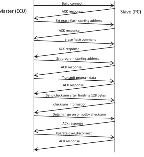
3.3 Online Upgrade Process
The user start the upgrade system by using the CONNECT command in upper machine PC (master).
The upper machine control datatransmission when it begin working. Each time the upper machinesenda command, the timer starts. If the upper machine doesn’t receive feedback from the lower machine ECU (slave)
0xC00000 0xC08000 0xC1FFFF Application code area
before the timer decreases to zero, the upper machine send the command again.The working process of the
upper machine is shown in figure 2.
The PC execute operation according to the command it receives , the specific process is as follows:
(1) Send the CONNECT command along with the slave address, waiting for DTO.If it receives correct DTO
(namely the ACK response), enter (2), or return to(1).
(2) Send the SET_MTA command containing erase address information, waiting for DTO. If it receives correct
DTO (namely the ACK response), enter (3), or return to(2).
(3) Send the CLEAR_MEMORY command to erase the flash, waiting for DTO.If it receives correct DTO, enter
(4), or return to(3).
Figure 2. master working process
(4) Send the SET_MTA command containing the address information of programming , waiting for DTO.If it
receives correct DTO, enter (5), or return to(4).
(5) Send the programming PROGRAM command and wait for confirmation DTO.If it receives correct DTO
confirmation, PC will judge whether it has send 128 bytesof data ( one data page), if the result is "yes", enter
(6), otherwise return to (5) to sendthe next frame of data.
(6) Send checksumcommand BUILD_CHKSUM, waiting for DTO. When the DTO containingno checksum
error, the PC will judge whether the next data is the file end record (01), if "yes", enter (7), otherwise return to
(5) to send the nextdata block. However, if the DTO contains checksum error, enter (5) to send the data block
again.
(7) Send DISCONNECT command,end upgrade.
Working process of the slave (ECU) is shown in figure 3.
According to the command the slave receives, it executes corresponding instructions. The specific work process Upgrate over,disconnect
ACK response
Determin go on or not by checksum
ACK response checksum information
Send checksum after finishing 128 bytes ACK response
Transmit program data ACK response
Set program starting address ACK response
Erase flash command ACK response
Set erase flash starting address ACK response
Build connect
is as follows:
(1) If the command is CONNECT command, check the slave address contained in the CONNECT message. If
it is the local address, return the master the DTO containing the node address confirmation information,
otherwise, disconnect with the master.
After the connection is established:
(2) If the slave receives SET_MTA command, and the address information is in the range of valid address, save
this address information and return a DTO with confirmation message, otherwise return a DTO containing
address beyond the scope error.
(3)If the slave receives CLEAR_MEMORY command, , erase the corresponding sector of flash according to
the message in SET_MTA command. Then return a DTO with confirmation message.
Figure 3.slave working process
(4) If the slave receives the PROGRAM command, save the data into data buffer, then return a DTO with
confirmation message.
(5) If the slave receives BUILD_CHKSUM command, checksum the data buffer, write the data into the
specified address in flash if the checksum is correct. Clear the buffer after finishing writing. Return a DTO with
the checksum result message.
(6) If the slave receives DISCONNECT command, it interrupts connection with the master. It indicates the end
of the upgrade. Then reboot the system to run the new application.
IV.
ONLINE UPGRADE FUNCTION VALIDATION
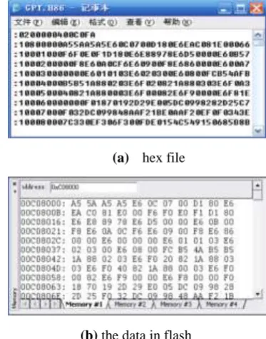
Actual test result of the plan: figure 4(a) is an application code hex file. Figure 4(b) shows the data in
debugging window,which has been programmed into flash memory. We can see that the application code has
been downloaded into the specified memory correctly, achieving the application code upgrade function.
(a) hex file
(b) the data in flash
V.
THE CONCLUSION
This paper comes up with aplan of the ECU online upgrade system which is based on CAN bus and
communicates via CCP protocol. The plan is applied in the programming of XC167CI MCUsuccessfully and is
to operate. The method of online upgrade system can be also applied to other ECUs in cars, as all the ECUs use
the unified protocol and has strong scalability. Ultimately, all the ECUs can be application code upgraded
through the CAN network.
REFERENCE
[1]. Jiang Xiaomei, Li XiangHe. The remote online upgrade technology based on ARM of IAP[J]. Computer
Application, 2008, 28(2): 519-521.
[2]. Yin Shuming, Wang Yihuai. Multi-user program online programming technology in embedded system[J].
Computer Application, 2009,35(5):37-39.
[3]. Han Jianghong, Chang Anyun. The research and implementation of online programming techniques in car body
control system[C]//The 18th national computer technology and application of academic conference
proceedings. Ningbo City, [Publisher unknown], 2007.
[4]. Feng Jing, Wang Junxi, Zhuo Bin. The CAN communication module based on CCP protocol of research and
development in electronically controlled engine calibration system[J]. Chinese internal combustion engine
engineering, 2003, 24(4): 33-37.
[5]. Infineon Technologies AG.XC164-16 User’s Manual(v2.1)[Z].2004.
[6]. Yan Z,Kejin B (2011) Design and implementation of Bootloader of vehicle control unit. Comput Eng