19
AN ESTIMATION OF MULTILEVEL INVERTER FED
INDUCTION MOTOR DRIVE
K.RAMANI AND DR.A. KRISHNAN SMIEEE
Senior Lecturer in the Department of EEE at K.S.Rangasamy College of Technology, Tiruchengode, INDIA
Dean, K.S.Rangasamy College of Technology, Tiruchengode and guide at Periyar University, Salem and Anna University, Chennai, INDIA
ABSTRACT
This paper highlights a hybrid multilevel inverter for A.C electrical drives. In recent days multilevel inverters has become very popular for motor drive applications of industry .Multilevel pulse width modulation inversion is an effective solution for increases the level number of the output wave form and thereby dramatically reduced to the harmonics and total harmonic distortion.In conventional methods, the need of converters to supply the cells of reversible multilevel converters increases the cost and losses of such inverters. In this new topology the output waveform consists of SVdc; S-number of stages and the associated number of level equal 2s+1 – 1. The output waveform has 15 levels. Moreover, the stage with
higher DC link voltage has lower switching frequency and thereby reduces the switching losses. Comparison of conventional results will be presented.
Keywords: Estimation, Hybrid Multilevel Inverter, Modulation Inversion, Switching, Comparison
I. INTRODUCTION
Multilevel inverters have very important development for high power medium voltage AC drives. Quite a lot of topologies have found industrial approval; Neutral Point Clamped, flying capacitor, H-bridge, cascaded with separated DC source, several control and modulation strategies have been developed Pulse Width Modulation (PWM), Sinusoidal PWM, Space Vector PWM and Selective harmonic eliminations
[1-3]etc.
A most important issue with multilevel inverter is eliminating the harmonics from the output voltage. The output voltage of the inverter must meet maximum Total Harmonics Distortion (THD) boundaries as specified [4].
Every individual inverter is capable of generating three different voltage output +Vdc ,
0, -Vdc by connecting the dc source to the ac
output side by different combinations of the four switches S1 , S2 , S3 and S4 [1]. The synthesize ac
output voltage waveform of the sum of all the individual inverter’s outputs. The number of output phase voltage level of cascade multilevel inverter is 2s+1 where S is the number of dc sources. This outstandingly increases the level number of the output wave form and thereby
dramatically reduced to the low order harmonics and total harmonic distortion. One of the foremost motives for developing the multilevel inverter is to reduce cost [5].
20
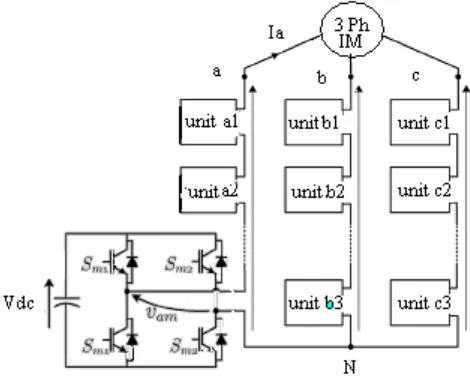
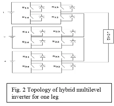
II. HYBRID H-BRIDGE MULTILEVEL INVERTER
The H-bridge multilevel inverter is in figure.1. The output waveform consists of SVdc; S-number of DC source or stages and the associated number of level equal 2s+1 – 1. The
output has 15 levels for S=3. , +7, +6, +5,
+4, +3, +2, +1 and 0.Fig 2 and fig 3.ilustrate
the relationship of the switching states and output voltages for H-bridge multilevel inverter P and N apply the output voltage of the stages with VDC = 1V, 2V and 4V, with positive &
negative polarities correspondingly. More over 0 indicates that the associated stage is in a free wheeling state which means that the terminals of the output are both connected to the positive and negative DC link. There are two combinations of switching states for Vout =
±
2 Vdc and threecombinations for Vout
±
3 Vdc &±
1Vdc . Oneof the advantages is that the stage with the higher DC link voltage has a lower number of commutations. Hereby reducing the switching losses.
.
Fig. 3 output voltage waveform of inverter
Table.1 OUTPUT VOLTAGES AND SWITCHING STATES FOR THE HYBRID INVERTER
Output voltages and switching states for the hybrid inverter, S=3
Vdc Vout
-7V -6V -5V -4V -3V -2V -1V 0V 1V 2V 3V 4V
5V 6V 7V
1V N 0 P N 0 P N N 0 0 N P P 0 P N N 0 0 P N P 0 P N 0 P
2V N N N 0 0 0 N P N P 0 N P 0 0 P N P N P 0 N 0 0 P P P
4V N N N N N N 0 N 0 N 0 0 N 0 0 0 P 0 P 0 P P P P P P P
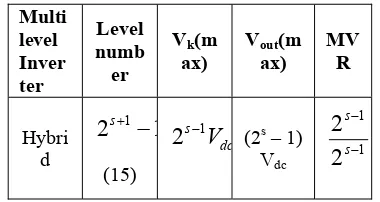
21 Table.1 consists of output voltage and switching state for hybrid multilevel inverter. For S=3; S is number of stage or number of Dc source. Hence the output has 15 levels (+7 and 0). Table .2 shows the performance the hybrid multilevel inverter. It contains the expression of number of levels, maximum output voltage of hybrid and the maximum value of the output voltage i.e. maximum voltage ratio (MVR).
TABLE .2.HYBRID MULTILEVEL INVERTER PERFORMANCE RESULTS
Multi level Inver ter Level numb er
Vk(m
ax) Voutax) (m MVR
Hybri d
1
2
s+1−
(15)
dc s 1
V
2
− (2s – 1)Vdc 1
1
2
2
− − s sA factor known as the maximum voltage ratio (MVR), it is defined as the ratio of maximum output voltage of H-bridge, Vk (max) to the maximum value of the output voltage, Vout (max)
defined by (1) is used as the performance index.
MVR =
(max)
(max)
out kV
V
(1) a) HarmonicsHarmonics are undesirable current or voltage[6-9]. They exist at some multiple or fraction of the fundamental frequency. The harmonics causes in three ways are a) The application of a non sinusoidal driving voltage to a circuit containing non linear impedance b) The application of a sinusoidal driving voltage to a circuit containing non linear impedance. c) The application of a non sinusoidal driving voltage to a circuit containing linear impedance.
The harmonics orders and magnitude depend on the inverter type and the controlling methods for example in single phase VSI, the output voltage waveform typically consists only of odd harmonics. The even harmonics are absent due to the half wave symmetry of the output voltage harmonics. For three phase VSI, in addition to the even harmonic triplen (third and multiple of third harmonics) are also absent.
The harmonic spectra depend on the switching frequency and the control method.
b) PWM for harmonic reduction
PWM technique is extensively used for eliminating harmful low-order harmonics in input and output voltage and current of static power. In PWM control, the inverter switches are turned ON and OFF several times during a half cycle and output voltage is controlled by varying the pulse width. At present, available PWM schemes can be broadly classified as carrier modulated sinusoidal PWM (SPWM) and pre calculated programmed PWM schemes. The inverters of the pulses are varied by charging the amplitude of the sinusoidal wave form. In this method the lower order harmonics are eliminated. As the switching for increases more harmonics can be eliminated. The limiting factors are the switching devices speed, switch losses & power ratings.
c) Harmonic Elimination in Multi Level Inverter
The output voltage V (t) of the multi level inverter can be expressed in Fourier series as
( )
t
v
=∑
n∞=1(
a
nsin
n
α
n+
b
ncos
n
α
n)
(2)Due to quarter wave symmetry of the output voltage the even harmonics are absent (
b
n=
0
) and only odd harmonics are present. The amplitude of then
th harmonica
nis expressed only with the first quadrant switching anglem
α
α
α
α
1, 2,
3,...
n
a
=∑
∞ =1
cos
4
k k dcn
n
V
α
π
(3)0
<2
...
2π
α
α
α
α
<
<
<
m<
(4) For any odd harmonics can be expressed up to kth term, where m is the number of variablecorresponding to switching angle
α
1throughm
α
of the first quadrant22 THD
=
l fundamenta
1
2 1
2
2
)
( ⎥
⎦ ⎤ ⎢
⎣ ⎡
∑
∞=
n
thharmoniccomponents
n
(5)
III. INVERTER EFFICIENCY
The efficiency of a hybrid inverter is higher than this of a conventional inverter, for the applications where the switching losses are biggest. The efficiency of the proposed structure is between the efficiency of the ideal hybrid inverter and this of a conventional multilevel inverter fully supplied with dc-dc converters. At the same time, it is an attractive solution to get a large number of levels together with a good efficiency.
IV.SIMULATION RESULTS
(a)
(a)
(b)
(b)
(c) (c)
0 0.2 0.4 0.6 0.8 1 1.2 1.4 1.6 1.8 2
x 104 -300
-200 -100 0 100 200 300
Time in msec
V
olta
ge
in
V
olts
Phase to Ground Voltage
0 0.2 0.4 0.6 0.8 1 1.2 1.4 1.6 1.8 2 x 10⁴ -400
-300 -200 -100 0 100 200 300
400 Phase to Phase Voltage
Time in msec
Vol
tage i
n V
ol
ts
0 0.5 1 1.5 2 x 10⁵ -60
-40 -20 0 20 40
60 Stator Current
Time in msec
C
urre
nt
in
A
m
23
(d) (d)
(e) (e)
Fig 4.Hybrid multilevel inverter for 15 levels. Fig 5. Hybrid multilevel inverter for 7 levels.
a) Phase to ground voltage (Volts) a) Phase to ground
voltage (Volts)
b) Phase to phase voltage (Volts) b) Phase to phase
voltage (Volts)
c) Stator current (Amps) c) Stator current
(Amps)
d) Torque (Nm) d) Torque (Nm)
e) Speed of the motor (rpm) e) Speed of the motor
(rpm)
V. RESULT ANALYSIS
Steady state phase to ground voltage is shown in fig 4. (a); the high number of levels generated by 15 level inverter can be clearly appreciated in the voltage. To be increase the number of level nearly gets sinusoidal voltage waveform compares the fig .5 (a) consists of 7 level. The same ways fig .4 (b) and fig.5 (b) are phase to phase voltage.
Fig 4. (c) and fig 5. (c) are illustrated the stator currents. The Fig 4. (c) consists of high starting currents about 40 amps but it should be reach very quickly to get steady state. But the Fig 5. (c) consists of high starting currents about 40 amps but it should be take some delay time to
get steady state and also gets harmonics in the waveform visibly.
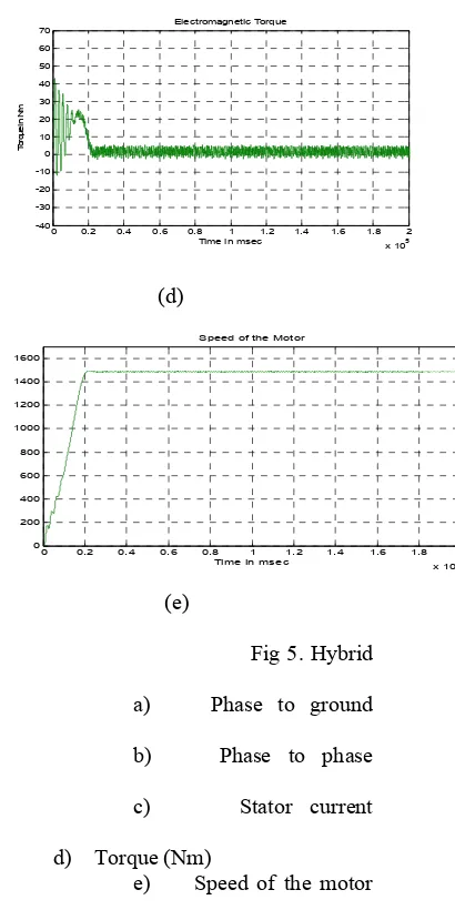
Fig 4. (d) and fig 5. (d) are involves electromagnetic Torque. The Fig 4. (d) consists of high starting torque about 60 Nm but it should be reach very quickly to get steady state about 0.2 msec. But the Fig 5. (d) consists of high starting torque about 40 Nm.but it should be take after 0.2msec delay time to get steady state and also gets harmonics in the waveform visibly.
Fig 4. (e) and fig 5. (e) are involves Speed of the motor. Fig 4.(e) illustrate the motor speed 1500 rpm which is reaches 0.1 msec and its maintain as constant. but the fig.5 (e) illustrate the motor speed 1500 rpm which is take time0.2 msec to reach and its maintain as
0 0.2 0.4 0.6 0.8 1 1.2 1.4 1.6 1.8 2 x 10⁵
-40 -30 -20 -10 0 10 20 30 40 50 60
70 Electromagnetic Torque
Time in msec
T
or
qu
e i
n
N
m
0 0.2 0.4 0.6 0.8 1 1.2 1.4 1.6 1.8 2 x 10⁵ -40
-30 -20 -10 0 10 20 30 40 50 60
70 Electromagnetic Torque
Time in msec
Tor
que i
n N
m
0 0.2 0.4 0.6 0.8 1 1.2 1.4 1.6 1.8 2 x 10⁵
0 200 400 600 800 1000 1200 1400 1600 1800
Speed
Time in msec
S
peed
in
R
PM
0 0.2 0.4 0.6 0.8 1 1.2 1.4 1.6 1.8 2 x 10⁵ 0
200 400 600 800 1000 1200 1400 1600
Speed of the Motor
Time in msec
S
pe
ed i
n R
24 constant. and finally the result analysis says the number of levels should increases the harmonics less and good performance.
VI. CONCLUSION
An improved hybrid multilevel inverter structure is proposed. The proposed hybrid inverter scheme is to get the better sinusoidal output compare with low level inverters. The asymmetrical multilevel inverter is to obtain a high resolution. The proposed a way to decrease the number of insulated supplies and to get better the efficiency. The hybrid multilevel inverter technique is used to improve the level of inverter and extends the design flexibility and reduced the harmonics.
REFERENCES
[1] Y.S.Lai and F.S.Shyu. “Topology for hybrid multi level inverter”, IEE Proc-Electr.Power Appl.Vol 149,No 6 nov 2002.
[2] O.M. Mueller and J.N. Park. “Quasi-linear IGBT inverter topologies”. APEC’94 Conference Proceedings, 1:253–259, February 1994.
[3] M.D. Manjrekar, P.K. Steimer, and T.A. Lipo. “Hybrid multilevel power conversion system: A competitive solution for high power applications”. IEEE Transations on Industry Applications, 36(3):834–841, May/June 2000.
[4] K.A. Corzine, S.D. Sudhoff, and C.A. Whitcomb. “Performance characteristics of a cascaded two-level converter”. IEEE Transactions on Energy Conversion, 14(3), September 1999.
[5] A. Rufer, M. Veenstra, and K. Gopakumar. “Asymmetric multilevel converter for high resolution voltage phase generation”.
EPE’99.
[6] Gui-jia su. “Multilevel DC link inverter” .IEEE trans on industry appl.Vol.41.No.3.May/june 2005.
[7] M. Veenstra and A. Rufer. “Control of a hybrid asymmetric multi- level inverter for competitive medium-voltage industrial drives”. IAS’2003, 1:190 – 197, October 2003.
[8] ] S. Mariethoz and A.C. Rufer. Design and control of asymmetrical multilevel inverters.
IECON’02, November 2002.
[9]A.k.Ali Othman “Elimination of harmonics in multi level inverters with non equal DC
sources using PSO”.IEEE conf.proce EPE PEMC 2008.
BIOGRAPHIES
K.Ramani was born in
Vedaranyam on May 7, 1982. He is graduated in 2004 from Bharathiar University, Coimbatore and post graduated in 2006 at Anna University, Chennai. He is a Research scholar in Anna University Chennai under the guidance of Dr.A.Krishnan, Dean, K.S.Rangasamy College of Technology, Tiruchengode.. He is currently working as a senior lecturer in the department of EEE at K.S.Rangasamy College of Technology, Tiruchengode from January 2006 onwards. He published 10 international/national conferences, journals. his research interest involves in power electronics, inverter, modeling of induction motor and optimization techniques. He is guiding UG, PG Students. He is an ISTE, IETE member.
Dr.A.Krishnan received