VOLUME 3, ISSUE 3, March-2017
63 | P a g e
DESIGN, ANALYSIS AND OPTIMIZATION OF BRAKE DISC MADE OF
COMPOSITE MATERIAL FOR A MOTOR CYCLE
MR. SAGAR B. PORLEKAR
ME (CAD/CAM/CAE) Student, K.I.T.'s College of Engineering, Kolhapur, Maharashtra, India.
PROF. DR. S. G. BHATWADEKAR
Department of ProductionEngg, K.I.T.'s College of Engineering, Kolhapur, Maharashtra, India.
PROF. G.R KULKARNI
Department of ProductionEngg, K.I.T.'s College of Engineering, Kolhapur, Maharashtra, India.
ABSTRACT:
Vehicle braking system is considered as one of the most fundamental safety-critical systems in modern vehicles as its main purpose is to stop or decelerate the vehicle. The frictional heat generated during braking application can cause numerous negative effects on the brake assembly such as brake fade, premature wear, thermal cracks and Disc Thickness Variation (DTV). In the past, surface roughness and wear at the pad interface have rarely been considered in studies of thermal analysis of a disc brake assembly using finite element method. Motivation of this project is to reduce the weight of disc rotor by replacing conventional materials with composites. The objective of this research is to design and manufacturing Aluminum metal matrix composite disc brake by using Stir casting method. AL6061 is used as a base alloy and Al2O3 matrix
material. After manufacturing define thermal performance of disc brake models. Thermal performance was a key factor which was studied using the 3D model in Finite Element Analysis simulations. Experimental validation of FEA RESULTS will enable to understand how implemented disc brake works more efficiently, which can help to reduce the accident that may happen in each day.
KEYWORDS: Brake disc, Thermal analysis, Al6061, Stir casting.
I. INTRODUCTION:
Disc brakes are an important component of a vehicle retardation system. They are used to stop or adjust the speed of a vehicle with changing road and traffic conditions. During braking, a set of stationary pads is pressed against a rotating disc to reduce the speed. The heat generated at the disc-pad interface due to friction causes the disc surface temperature to rise in a short period of time. This heat gets transferred to the vehicle and the environment, and the disc cools down. As a
result of higher temperatures, in addition to local changes of the contact surfaces, there are deformations occurring in the disc and the pad. Due to different geometries of discs, each disc has different geometrical constraints for the thermal expansion. After some brake cycles, the frictional heat generated during braking application can cause numerous undesirable effects on the brake disc such as brake fade [2,13,10,11], thermal cracks [19,10,11,20], wear [19,10,11], permanent damage [20], breakage in brake disc due to high stress [10], disc thickness variation [8], formation of hot spots [20]. Macroscopic cracks [10] might also appear on a disc surface in the radial direction, affecting the performance and life of a brake disc. It has been shown, that during hard braking, high compressive stresses are generated in the circumferential direction on the disc surface which causes plastic yielding. But when the disc cools down, these compressive stresses transform to tensile stresses. When this kind of stress-strain behaviour is repeated due to frequent braking actions, stress cycles with high amplitudes are developed which might generate low cycle fatigue cracks after repeated braking cycles.
II. FINITE ELEMENT ANALYSIS:
The commercial Finite Element Analysis (FEA) software, ANSYS has been used to create and analyze the models.
CAD MODELING:
VOLUME 3, ISSUE 3, March-2017
64 | P a g e
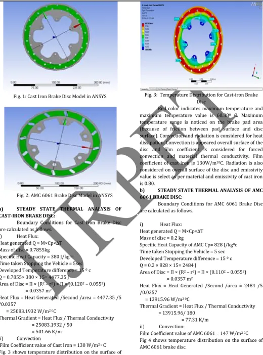
Fig. 1: Cast Iron Brake Disc Model in ANSYS
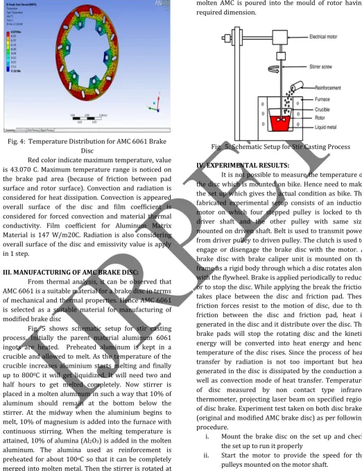
Fig. 2: AMC 6061 Brake Disc Model in ANSYS
a) STEADY STATE THERMAL ANALYSIS OF CAST-IRON BRAKE DISC:
Boundary Conditions for Cast Iron Brake Disc are calculated as follows.
i) Heat Flux:
Heat generated Q = M×Cp×ΔT Mass of disc = 0.7855kg
Specific Heat Capacity = 380 J/kg0c
Time taken Stopping the Vehicle = 5sec Developed Temperature difference = 15 0 c
Q = 0.7855× 380 × 15= 4477.35 J
Area of Disc = Π × (R2 – r2) = Π × (0.1202 – 0.0552)
= 0.0357 m2
Heat Flux = Heat Generated /Second /area = 4477.35 /5 /0.0357
= 25083.1932 W/m2 0C
Thermal Gradient = Heat Flux / Thermal Conductivity = 25083.1932 / 50
= 501.66 K/m ii) Convection
Film Coefficient value of Cast Iron = 130 W/m2 o C
Fig. 3 shows temperature distribution on the surface of cast iron brake disc.
Fig. 3: Temperature Distribution for Cast-iron Brake Disc
Red color indicates maximum temperature and maximum temperature value is 60.380 C. Maximum
temperature range is noticed on the brake pad area (because of friction between pad surface and disc surface). Convection and radiation is considered for heat dissipation. Convection is appeared overall surface of the disc and film coefficient is considered for forced convection and material thermal conductivity. Film coefficient of cast iron is 130W/m20C. Radiation is also
considered on overall surface of the disc and emissivity value is select as per material and emissivity of cast iron is 0.80.
b) STEADY STATE THERMAL ANALYSIS OF AMC 6061 BRAKE DISC:
Boundary Conditions for AMC 6061 Brake Disc are calculated as follows.
i) Heat Flux:
Heat generated Q = M×Cp×ΔT Mass of disc = 0.2 kg
Specific Heat Capacity of AMC Cp= 828 J/kg0c
Time taken Stopping the Vehicle = 5 sec Developed Temperature difference = 15 0 c
Q = 0.2 × 828 × 15= 2484 J
Area of Disc = Π × (R2 – r2) = Π × (0.1102 – 0.0552)
= 0.0357 m2
Heat Flux = Heat Generated /Second /area = 2484 /5 /0.0357
= 13915.96 W/m2 0C
Thermal Gradient = Heat Flux / Thermal Conductivity = 13915.96/ 180
= 77.31 K/m ii) Convection:
Film Coefficient value of AMC 6061 = 147 W/m2 0C
VOLUME 3, ISSUE 3, March-2017
65 | P a g e
Fig. 4: Temperature Distribution for AMC 6061 Brake Disc
Red color indicate maximum temperature, value is 43.070 C. Maximum temperature range is noticed on the brake pad area (because of friction between pad surface and rotor surface). Convection and radiation is considered for heat dissipation. Convection is appeared overall surface of the disc and film coefficient is considered for forced convection and material thermal conductivity. Film coefficient for Aluminum Matrix Material is 147 W/m20C. Radiation is also considering overall surface of the disc and emissivity value is apply in 1 step.
III. MANUFACTURING OF AMC BRAKE DISC:
From thermal analysis, it can be observed that AMC 6061 is a suitable material for a brake disc in terms of mechanical and thermal properties. Hence AMC 6061 is selected as a suitable material for manufacturing of modified brake disc
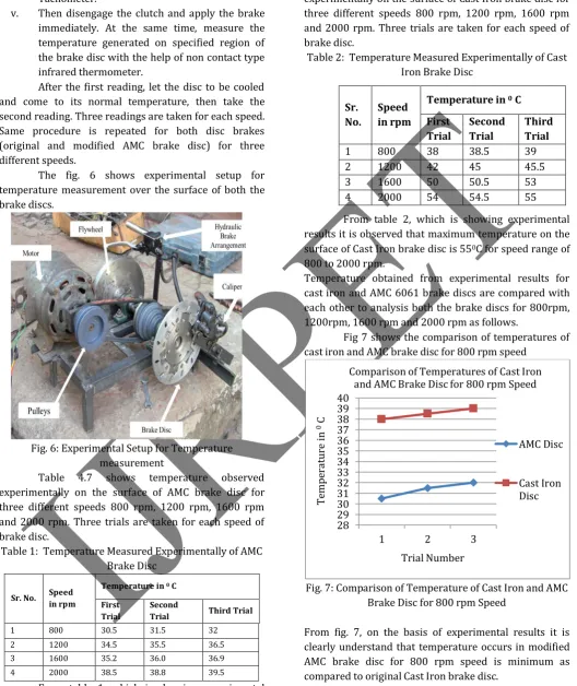
Fig. 5 shows schematic setup for stir casting process. Initially the parent material aluminum 6061 ingots are heated. Preheated aluminum is kept in a crucible and allowed to melt. As the temperature of the crucible increases aluminium starts melting and finally up to 8000C it will get liquidized. It will need two and
half hours to get melted completely. Now stirrer is placed in a molten aluminum in such a way that 10% of aluminum should remain at the bottom below the stirrer. At the midway when the aluminium begins to melt, 10% of magnesium is added into the furnace with continuous stirring. When the melting temperature is attained, 10% of alumina (Al2O3) is added in the molten
aluminum. The alumina used as reinforcement is preheated for about 100oC so that it can be completely
merged into molten metal. Then the stirrer is rotated at 600 rpm for 10 minutes to achieve high integrity and homogeneity of the molecules. After 10 minutes the
molten AMC is poured into the mould of rotor having required dimension.
Fig. 5: Schematic Setup for Stir Casting Process
IV. EXPERIMENTAL RESULTS:
It is not possible to measure the temperature of the disc which is mounted on bike. Hence need to make the set up which gives the actual condition as bike. The fabricated experimental setup consists of an induction motor on which four stepped pulley is locked to the driver shaft and the other pulley with same size mounted on driven shaft. Belt is used to transmit power from driver pulley to driven pulley. The clutch is used to engage or disengage the brake disc with the motor. A brake disc with brake caliper unit is mounted on the frame as a rigid body through which a disc rotates along with the flywheel. Brake is applied periodically to reduce or to stop the disc. While applying the break the friction takes place between the disc and friction pad. These friction forces resist to the motion of disc, due to the friction between the disc and friction pad, heat is generated in the disc and it distribute over the disc. The brake pads will stop the rotating disc and the kinetic energy will be converted into heat energy and hence temperature of the disc rises. Since the process of heat transfer by radiation is not too important but heat generated in the disc is dissipated by the conduction as well as convection mode of heat transfer. Temperature of disc measured by non contact type infrared thermometer, projecting laser beam on specified region of disc brake. Experiment test taken on both disc brakes (original and modified AMC brake disc) as per following procedure.
i. Mount the brake disc on the set up and check the set up to run it properly
ii. Start the motor to provide the speed for the pulleys mounted on the motor shaft.
VOLUME 3, ISSUE 3, March-2017
66 | P a g e
iv. Measure the speed of brake disc with the help of Tachometer.
v. Then disengage the clutch and apply the brake immediately. At the same time, measure the temperature generated on specified region of the brake disc with the help of non contact type infrared thermometer.
After the first reading, let the disc to be cooled and come to its normal temperature, then take the second reading. Three readings are taken for each speed. Same procedure is repeated for both disc brakes (original and modified AMC brake disc) for three different speeds.
The fig. 6 shows experimental setup for temperature measurement over the surface of both the brake discs.
Fig. 6: Experimental Setup for Temperature measurement
Table 4.7 shows temperature observed experimentally on the surface of AMC brake disc for three different speeds 800 rpm, 1200 rpm, 1600 rpm and 2000 rpm. Three trials are taken for each speed of brake disc.
Table 1: Temperature Measured Experimentally of AMC Brake Disc
Sr. No. Speed in rpm
Temperature in 0 C
First Trial
Second
Trial Third Trial
1 800 30.5 31.5 32
2 1200 34.5 35.5 36.5
3 1600 35.2 36.0 36.9
4 2000 38.5 38.8 39.5
From table 1, which is showing experimental results it is observed that maximum temperature on the surface of AMC brake disc is 39.50C for speed range of
800 to 2000 rpm.
Table 2 shows temperature observed experimentally on the surface of Cast Iron brake disc for three different speeds 800 rpm, 1200 rpm, 1600 rpm and 2000 rpm. Three trials are taken for each speed of brake disc.
Table 2: Temperature Measured Experimentally of Cast Iron Brake Disc
From table 2, which is showing experimental results it is observed that maximum temperature on the surface of Cast Iron brake disc is 550C for speed range of
800 to 2000 rpm.
Temperature obtained from experimental results for cast iron and AMC 6061 brake discs are compared with each other to analysis both the brake discs for 800rpm, 1200rpm, 1600 rpm and 2000 rpm as follows.
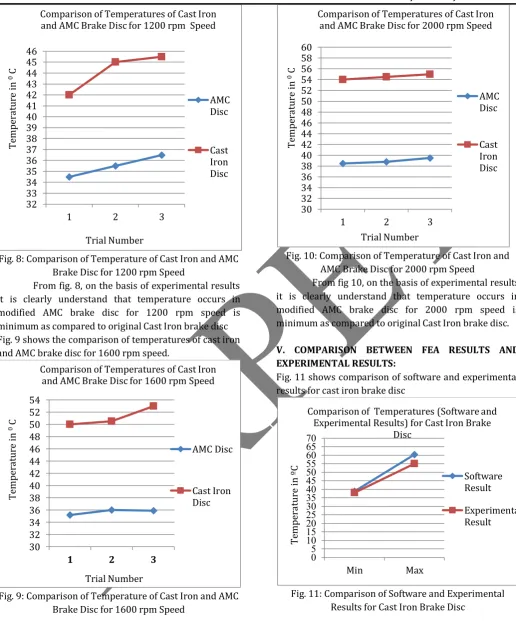
Fig 7 shows the comparison of temperatures of cast iron and AMC brake disc for 800 rpm speed
Fig. 7: Comparison of Temperature of Cast Iron and AMC Brake Disc for 800 rpm Speed
From fig. 7, on the basis of experimental results it is clearly understand that temperature occurs in modified AMC brake disc for 800 rpm speed is minimum as compared to original Cast Iron brake disc.
Fig 8 shows the comparison of temperatures of cast iron and AMC brake disc for 1200 rpm speed.
28 29 30 31 32 33 34 35 36 37 38 39 40
1 2 3
Te
mp
er
at
ur
e
in
0C
Trial Number
Comparison of Temperatures of Cast Iron and AMC Brake Disc for 800 rpm Speed
AMC Disc
Cast Iron Disc
Sr. No.
Speed in rpm
Temperature in 0 C
First Trial
Second Trial
Third Trial
VOLUME 3, ISSUE 3, March-2017
67 | P a g e
Fig. 8: Comparison of Temperature of Cast Iron and AMC Brake Disc for 1200 rpm Speed
From fig. 8, on the basis of experimental results it is clearly understand that temperature occurs in modified AMC brake disc for 1200 rpm speed is minimum as compared to original Cast Iron brake disc Fig. 9 shows the comparison of temperatures of cast iron and AMC brake disc for 1600 rpm speed.
Fig. 9: Comparison of Temperature of Cast Iron and AMC Brake Disc for 1600 rpm Speed
From fig. 9, on the basis of experimental results it is clearly understand that temperature occurs in modified AMC brake disc for 1600 rpm speed is minimum as compared to original Cast Iron brake disc.
Fig. 10 shows the comparison of temperatures of cast iron and AMC brake disc for 2000 rpm speed.
Fig. 10: Comparison of Temperature of Cast Iron and AMC Brake Disc for 2000 rpm Speed
From fig 10, on the basis of experimental results it is clearly understand that temperature occurs in modified AMC brake disc for 2000 rpm speed is minimum as compared to original Cast Iron brake disc.
V. COMPARISON BETWEEN FEA RESULTS AND EXPERIMENTAL RESULTS:
Fig. 11 shows comparison of software and experimental results for cast iron brake disc
Fig. 11: Comparison of Software and Experimental Results for Cast Iron Brake Disc
From fig. 11, it is observed that the experimental results are closed to the FEA results for maximum and minimum temperature observed on the surface of cast iron brake disc. The maximum temperature obtained of cast iron brake disc by FEA and experimental test are 60.38 0C and 55 0C respectively. The minimum
32 33 34 35 36 37 38 39 40 41 42 43 44 45 46
1 2 3
Te mp er at ur e in 0C Trial Number
Comparison of Temperatures of Cast Iron and AMC Brake Disc for 1200 rpm Speed
AMC Disc Cast Iron Disc 30 32 34 36 38 40 42 44 46 48 50 52 54
1 2 3
Te mp er at ur e in 0C Trial Number
Comparison of Temperatures of Cast Iron and AMC Brake Disc for 1600 rpm Speed
AMC Disc Cast Iron Disc 30 32 34 36 38 40 42 44 46 48 50 52 54 56 58 60
1 2 3
Te mp er at ur e in 0C Trial Number
Comparison of Temperatures of Cast Iron and AMC Brake Disc for 2000 rpm Speed
AMC Disc Cast Iron Disc 0 5 10 15 20 25 30 35 40 45 50 55 60 65 70 Min Max Te mp er at ur e in ºC
Comparison of Temperatures (Software and Experimental Results) for Cast Iron Brake
Disc
Software Result
VOLUME 3, ISSUE 3, March-2017
68 | P a g e
temperature obtained by FEA and experimental test of cast iron brake disc are 38.85 0C and 38 0C respectively.
Fig. 12 shows comparison of maximum and minimum temperatures observed between software and experimental results for AMC 6061 brake disc.
Fig 12: Comparison of Software and Experimental Results for AMC 6061 Brake Disc
From fig. 12, it is observed that the experimental results are closed to the FEA results for maximum and minimum temperature observed on the surface of AMC 6061 brake disc. The maximum temperature obtained of AMC 6061 brake disc by FEA and experimental test are 60.38 0C and 55 0C respectively. The maximum
temperature obtained of AMC 6061 brake disc by FEA and experimental test are 37 0C and 30.5 0C respectively
VI. CONCLUSION:
The present study can provide a useful design tool and improve the brake performance of Disc brake system. This project focuses on finding a new material for the brake disc of motor cycle. Conventionally Cast iron rotors are used for disc brake and now a day’s stainless material also used. For improving the brake disc performance material properties are important. With the reference of literature composite material fulfill the required properties of brake disc. It is observed that brake disc result is very good for new composite material AMC 6061. The following conclusions can be drawn from the present Study.
The following conclusions can be drawn from the present Study-
1. Beauty of composite material is that it serves high strength with minimum weight. Motivation of this project is to reduce the weight of disc brake rotor
with high performance. So here the AMC 6061 brake disc is manufactured with the help of stir casting technique.
2. Aluminum 6061 alloy is the matrix or the base metal and Al2O3 in powder form is the reinforcement
material. Existing Cast iron disc brake rotor weight is 785.5 gm and weight of AMC disc brake rotor is 200gm. We achieve almost 74% weight reduction of brake disc for motorcycle. Reduction in the weight improves fuel economy and reduces emissions. 3. For measuring the temperature on disc brake rotor,
the experimental set up is fabricated to verify the design through experiment for improvement. During the braking condition for different speeds like 800 rpm, 1200 rpm, 1600 rpm, 2000 rpm measured the temperature over brake disc by using non contact type infrared thermometer.
4. From experimental results, It is observed that at every speed maximum temperature over the AMC brake disc is less than Cast iron brake disc. From thermal analysis done in ANSYS for AMC 6061 and cast iron brake disc it is observed that the maximum temperature rise for AMC 6061 is much less as compared to cast iron and thus on the basic of thermal analysis, AMC 6061 is the best preferable material for manufacturing brake disc of motorcycle. It is necessary to maintain temperature at a safe operating value to avoid brake fade.
5. In this project both experimental and analysis based simulations are carried out. The experimental results and FEA results are compared with each other for the validation of experimental results and found that temperature distribution over disc brake depends upon the heat dissipation capacity of the disc.
6. The cooling rate of the brake disc will be the measure of braking efficiency. More is the cooling rate efficiency, less will be the time required to recovery. Here experimentally proved AMC disc brake rotor is well performed than Cast iron brake disc and it is validated by FEA software ANSYS. 7. The present study can provide a useful design and
improve the brake performance of the Disc Brake system by using U.G. and ANSYS. Hence the Disc Brake design is safe based on the thermal analysis. AMC 6061 seems to be a good material for a brake disc.
8. Apart from these uses our model serves as a perfect starter for people doing research oriented in field of brakes and their modifications
0 5 10 15 20 25 30 35 40 45 50 55 60
Min Max
Te
mp
er
at
ur
e
in
ºC
Comparision of Temperatures (Software and Experimental Results) for AMC Brake
Disc
Software Result
VOLUME 3, ISSUE 3, March-2017
69 | P a g e ACKNOWLEDGEMENT:
It is my great pleasure to present the honor and sincere gratitude to my guide Prof. Dr. S. G. Bhatwadekar and Prof. R.R. Gad (Co-guide) helped in joining the hands in developing each and every step of this dissertation and for valuable guidance and constant encouragement during completion of dissertation work.
REFERENCES:
1) R. S. Kajabe, R.R.Navthar, “Optimization of Disc
Brake Rotor with Modified Shape”, International
journal of research in aeronautical and mechanical engineering, 2015,52-60.
2) Swapnil R. Abhang, D.P.Bhaskar, “Design and
Analysis of Disc Brake”, 2014, 165-167.
3) A.K.Matta, V.Purushottam, “Analysis of the novel
brake rotor using FEM”, 2014, 869-1 to 869-4.
4) Manjunath T V, Dr Suresh P M, “Structural and
thermal analysis of rotor disc of disc brake”, 2013,
7741-7749.
5) Prem Shankar Sahu, R. Banchhor, “ Fabrication
methods used to prepare Al metal matrix composites- A review ”, 2016,123-132.
6) Kashish Goyal and Karthikeyan Marwaha,
“Processing and properties of aluminium matrix composites: a short review ”,2016,54-59.
7) C.Saravanan, K Subramanian, D B Sivakumar, M. Sathyanandhan, R Sankara Narayanan, “ Fabrication of aluminium metal matrix composite –a review”,2015,82-87.
8) A.A. Adebisi, M.A. Maleque, M.M. Rahman“ metal
matrix composite brake rotor: historical
development and product life cycle analysis”, 2011,
471- 480.
9) P.K.Zaware, R.J.Patil, P.R.Sonawane ,“ Design
Modification and Optimisation Of Disc Brake Rotor ”,
2014, 1-6
10)Borchate Sourabh Shivaji, N.S. Hanamapure, Swapnil S. Kulkarni ,“ Design, Analysis And
Performance Optimization Of Disc Brake ”,2014,
25-27
11)D. Murali Mohan Rao, Dr. C. L. V. R. S. V. Prasad,T. Ramakrishna, “Experimental and Simulated Studies
on Temperature Distribution for Various Disc Brakes ”, 2013, 34-40
12)Karthik Ravi K.M, Qaiser Bashir, Rizwan Ahmad Dar, Yasir Muid Rather,“ experimental test rig for
surface temperature measurements in disc brakes”,2014,191-195.
13)Yathish K.O, Arun L.R, Kuldeep B3, Muthanna K.P, “Performance Analysis And Material Optimization Of
Disc Brake Using MMC”, 2013, 4101-4108
14)Telang A K, Rehman A, Dixit G ,Das S,“ Alternate
Materials In Automobile Brake Disc Applications With Emphasis On Al Composites- A Technical Review”, 2010, 35-46
15)Suraj S. Rana, Dr. W.S. Rathod, “Coupled
thermo-mechanical analysis of an automobile disc brake”,2016,7073-7077.
16)G.Shaikshavali, Dr. E.Venugopal goud , M.Murali mohan, “Mechanical properties of al6061 based
metal matrix composites reinforced with ceramic particulates and effect of age hardening on its tensile characteristics ”,2016,726-731.
17)Rajeshkumar Gangaram Bhandare, Parshuram M. Sonawane, “Preparation of aluminium matrix
composite by using stir casting method and it’s characterization”,2014, 148-155.
18)Lemi Abebe, Ramesh Babu Nallamothu, K.H.S Subrahmanyam, Seshu Kishan Nallamothu, Anantha Kamal Nallamothu, “Thermal analysis of disc brake
made of different materials”, 2016, 5-9
19)Jiguang Chen, Fei Gao, “Thermo-Mechanical
Simulation of Brake Disc Frictional Character by Moment of Inertial”, 2013, 227-232
20)P. Hosseini Tehrani, M. Talebi, “Stress And
Temperature Distribution Study in a Functionally Graded Brake Disc”, International Journal of
Automobile Engineering, 2012, 172-179
21)Albert kaufman, David spera, “Investigation of the
elastic-plastic stress state around reinforced outlet in a spherical shell,” NASA scientific and technical
publications, Washington, D.C., Feb 1965, PP 1-27. 22)C.R.Calladine, “On the design of reinforcement for
outlet and nozzles in thin spherical pressure vessel”,
Journal Mechanical Engineering science, 1966, vol8, no1, PP1-14.
23)Sagar Khivsara, Rucha Bapat, Nikhil Lele, Ameya Choudhari, Mahesh Chopade, “Thermal analysis and
optimisation of a ventilated disk brake rotor using CFD techniques”, 2015, 59-64.
24)Parsuram sah turaha, M.K. Pradhan Nikhil, “Concept
on single actuating braking system for two wheeler”,