Int. J. of Engg. Sci. & Mgmt. (IJESM), Vol. 4, Issue 3: July-September: 2014, 26-31
INTERNATIONAL JOURNAL OF ENGINEERING SCIENCES &
MANAGEMENT
EMERGING TECHNOLOGIES IN MACHINE TOOL
Nitin Dubey
1, Dr. P.K. Sharma
2, Prof. Suneel Kumar Shukla
31, 2, 3
Mechanical Engineering Department, NRI Institute of Science and Technology, Bhopal
(M.P.) India
ABSTRACT
Today the machine tool manufacturing industries in the world have been forced to adapt different technologies &
methodologies to enhance their productivity & to sustain in the global competition. Indian industries are also in the
boom of it.A file manufacturing industry located in India manufacturing various types of files e.g. flat, round,
triangular etc. Various operations are performed on these files such as cutting, hardening, grinding, sand blasting,
finishing etc. Different types of machines are used to perform various functions. Files are firstly hard by heating in
furnace then straightening it on machine then grind it on grinding machine then goes for stamping .After stamping files
goes for sand blasting to remove the black burr on it and to give it high surface finish. There is a grinding m/c which is
used to grind the files operated by hydraulic power pack which is based upon German technology which is near about
100 years old. There is problem usually with feed rate of the table. As this technology is outdated its maintenance is a
problem and also there is low productivity which is biggest problem. This affects the production, quality of files which
affects the brand name and profit of said industry. Our aim is to design the new hydraulic power pack which will
increase the feed rate of table ultimately enhancing the productivity and quality of files. The focus of writing the paper
is to introduce new technology, methodology which enhances the productivity. For this we have made literature review
of different concerned industries which gives different results. We have make use of this results in our paper.
Keywords: Industry, Files, Power pack, Profit, Hydraulic power jack. INTRODUCTION
Now this is an era of developing technologies. Day by
day there is development in available technologies,
machineries which intensified the market in this globe.
Various steps have been taken looking towards this.
Everyone is now trying to associate with these
changing technologies to produce good quality and
quantity product to meet customer requirement and
satisfy the customer. Industries began to realize that
there is need to improve the productivity within the
organization. A file manufacturing industry located in
India manufacturing various types of files e.g. flat,
round, triangular etc. File manufacturing is being
started with raw material in industry. Raw material is a
like a long strips of metal about 6 m in length.
Depending upon the type of file being manufactured
raw material is cut in different lengths. After cutting,
cut material is undergoes shot blasting in order to
remove the rust. Then these files are undergoes
shearing operation depending upon the length of file.
After that files goes for tank forging then for annealing
in order to impart hardness. Grinding operation then
performs on file on grinding machine then subjected to
blasting and oiling. Then it is going for
forming/cutting operation. Initially file length is taken
in excess in order to get the file of exact length it is
subjected to point cutting. There are so many
operations in which file bent slightly so remove the
bent file subjected to straightening. After this files are
hardened in furnace and cooled in NaCl solution then
files goes for ultrasonic cleaning to remove oil present
on files. To sharpen the cuts form on files it is
subjected to jet blasting at about 6 bar press with
Int. J. of Engg. Sci. & Mgmt. (IJESM), Vol. 4, Issue 3: July-September: 2014, 26-31
processes of file complete. Files then are inspected andgo for laser marking. With this file is manufactured
and ready to deliver to market.
NEED OF RESEARCH
There is a grinding m/c which is used to grind the files
operated by hydraulic power pack which is based upon
German technology which is near about 100 years old.
There is problem usually with feed rate of the table.
This grinding machine has hydraulic power pack this
uses the Bosch diesel pump system with the timing
adjustment for pumping the fluid. This is German
technology which does not use the standard hydraulics
in this system. These system carries various problem
associated with its maintenance. There is fast wearing of various parts such as rotor, axial disc etc who’s
repairing is not done and also there is problem with
availability of different spare parts of the system. If the
spare parts available then they are more costly beyond
the economic limit and also not match perfectly with
German power pack. Hence replaceable, wearing parts
have fewer life cycles. When pump is repaired its
repairing cost is near about rupees 100000/- even after
repairing there is problem with machine within 2-3
months. This system has high downtime and gives
near about 70% of designed speed and production also
up to 70%. There is daily 30% loss with production
and profit of company. Hence there is need to develop
a standard hydraulic power pack system which will
overcome the all above stated problems, improves
productivity, increase profit and quality and will be
helpful for various industries to improve their status,
profit etc and giving special contribution towards
developing methodologies and technologies in future
Int. J. of Engg. Sci. & Mgmt. (IJESM), Vol. 4, Issue 3: July-September: 2014, 26-31
OLD HYDRAULICS SYSTEMThe hydraulic circuit diagram for old power pack is
shown below and the pneumatic circuit for actuation
of lever is shown below.
CONSTRUCTIONAL DETAILS
The old power pack consists of diesel pump for oil
supply which was previously used in trucks for fuel
injection. It consists of pneumatically operated
cylinder as a directional control valve, damper in
order to avoid jerk.
WORKING
Different parts of power pack perform different
functions. Initially pneumatically operated cylinder
lifts the lever of pump as lever is lifted pump start
supplying oil. When lever is in left position it supply
the oil to damper and from damper it is supplied to
piston end of cylinder and rod extends towards
outside. As the rod extends table of grinding
machine is also extends along with the rod. The
travelling distance is fixed by the operator through
PLC. When table reaches to end position limit
switch sense the position and sends the signal to
pneumatic cylinder. The DCV of pneumatic circuit
takes the second position and air from the pneumatic
cylinder is expelled to atmosphere. Cylinder comes
back to its original position with due to spring force
acting on it. As cylinder comes back to its original
position pump lever also come back to previous
position. Then pump start supplying oil through the
right port to damper and from damper to table
cylinder.
The oil present in the cylinder in previous stroke is
returns back to the damper. Internally damper
consists of piston, as fluid inside the table cylinder
comes to damper it exerts force on that piston; the
fluid on other side of that piston goes back to tank.
This cycle is repeated no of times as per set by the
operator. And thus grinding operation is performs
on work piece mounted on table.
IMPROVED METHODOLOGY
Because of the no of drawbacks of old technology
we have developed the simple hydraulic power pack
which overcome the above stated drawbacks and
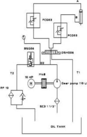
improve the productivity. The block diagram of
hydraulic circuit is as shown below.
The above block diagram shows various
components of new hydraulic power pack. The
name given in the blocks are designation of different
parts. The central block is directional control valve
(DSHG06), left block is pressure relief valve
(BSG06), and right block shows pressure measuring
devise (G2) and pump (P). The top block shows
flow control valves (FCG03) and bottom block
under the directional control valve shows the
cylinder sides i.e. piston side (A) and rod end side
(B) The block just below the cylinder block shows
tank (T1 & T2) which consist of oil. This is a very
simple circuit which uses the standard hydraulics
and easy to maintained. The actual hydraulic circuit
Int. J. of Engg. Sci. & Mgmt. (IJESM), Vol. 4, Issue 3: July-September: 2014, 26-31
Hydraulic Circuit DiagramCONSTRUCTIONAL DETAILS
The above circuit diagram shows various
components which are used in system. This system
is very simple, having low maintenance cost, easy to
operate, easy to understand etc. The constructional
details are shown in the diagram. It consists of oil
tank, two filters i.e. one simple filter and other one
with conditional check valve, gear pump which is
operated by 10hp motor through the coupling, single
pressure relief valve, single directional control valve
and single double acting cylinder.
WORKING
Working of this system is very simple. It consists of
oil reservoir through which oil is sucked by gear
pump. The oil is passes through the filter. The gear
pump of capacity 110 lpm is driven by motor of 10
hp through the coupling. The oil is pressurized in
pump and supplied to solenoid operated 4/3
directional control valve. When the DCV is in center
position, fluid is flows through the pressure relief
valve back to the tank.
When DCV is operated to position-I the oil flow
from pump to DCV and from DCV to FCV. The
check valve in FCV not allowed the fluid to flow
through it thus fluid flow through restricted path
thus metered flow is given to cylinder piston side
and piston is extend towards outside. The large force
is required to move the piston outside and this force
is given by fluid due to its pressure energy which
was imparted to it in gear pump. The motion of
cylinder rod is given to table of grinding machine.
As the rod extends the table is also move outwards
against the grinding wheel force. During this
grinding operation is being performed on work piece
mounted on table. The travelling distance of table is
fixed by operator according to the length of file;
table reaches final position and the pump is
unloaded through pressure relief valve. After table
travel the required distance the position of table is
being sense by limit switch and signal is fed to
solenoid operated DCV. After sensing the signal,
DCV moved to position-II.
When DCV is in position- II, pump flow is then
given to the rod end side of cylinder through the
FCV. Again in FCV the check valve do not allowed
the fluid to flow through it then it passes through
restricted path, thus metered flow reaches to rod end
side of cylinder. Rod then start to retract and thus
table also move back. The fluid which was present
in the cylinder piston side is then flow towards the
tank through the FCV valve. Again in the flow
control valve according to the property of fluid,
fluid passes through less resistance path. The check
valve in FCV offers low resistance to the fluid and
hence fluid passes through it to the DCV. From
DCV fluid goes to tank. After rod travel the set
distance its position is being sensed by limit switch
and signal is processed to solenoid operated DCV,
and DCV again move to position-I.
This process is repeated no of times which are set by
operator according to file length, surface finish
required, material to be removed etc. this process is
repeated within the few seconds and table moves to
Int. J. of Engg. Sci. & Mgmt. (IJESM), Vol. 4, Issue 3: July-September: 2014, 26-31
work piece and higher surface finish is obtained.The required amount of material is removed with
lower time then with the old hydraulic circuit.
RESULT AND ANALYSIS
It is found that the after the installation of new
power pack the overall productivity is increased. We
have collected the different data regarding the
production as shown in tables below. From the data
we have drawn the different graphs with the help of
data collected.
1. Production Vs Shift.
Power
1
2
3
pack
/Shift
Old
830
840
850
Power
Pack
New
1320
1353
1493
Power
Pack
It is clear from the data collected and a graph shows
that the production of files is increased with new
power pack. It increased the production of files near
about by 500 files per shift. This would increases
the profit of company
2. Time Vs Cycle.
Cycles
Time(Sec)
Old Power
New Power
Pack
Pack
10
18
11
20
35
23
30
59
35
40
65
44
3. Downtime Vs Month
Month
Time(hr)
Old Power
New Power
Pack
Pack
January
60
0
February
0
0
March
30
0
April
45
0
May
60
0
June
0
2
July
0
0
August
25
0
September
45
5
October
0
0
November
0
0
December
24
0
Time required for no of cycles is collected and from
the graph it is seen time required to complete the
cycles with new power pack is much lower than the
time required with old power pack.
Because of the non availability of spare parts and so
many reasons the downtime with old power pack is
much higher than new power pack. And it is seen
that the new power pack is near about maintenance
free. The installation cost of this new power pack is
near about 250000/- rupees. But looking towards the
production, maintenance and quality of files it
becomes economical. The installation cost of power
pack will recover in near about 4- 5 months and
Int. J. of Engg. Sci. & Mgmt. (IJESM), Vol. 4, Issue 3: July-September: 2014, 26-31
CONCLUSIONIn this work we have presented the optimum
solution to our industrial problems .This new power
pack is proved to be the best solution .With this new
power pack we have overcomes the all problems
related with the old power pack. The above all
results show that the installation of new power pack
is proved to be economical. The overall productivity
has been increased with new power pack. This
system makes the profit for industry with the very
low initial cost.
REFERENCES
1. An Adaptive Modeling Method for a Robot Belt
Grinding Process by Song Yixu, Lv Hongbo, and
Yang Zehong.
2. Feed control apparatus for grinding machine by
Takao Yoneda and Yasuji Sakakibara.
3. Book of Hydraulics by Anthony Esposito
4. Industrial Fluid Power by D. S. Pavaskar.
5. Books of grinding machine
6. Manufacturing catalogue of Yuken
7. ICF 2010. CHP Installation Database maintained
for the U.S. Department of Energy and Oak Ridge
National Laboratory.
8. NCASI 2008b. Memorandum from Reid Miner,
NCASI, to Becky Nicholson, RTI International.
Calculations Documenting the Greenhouse Gas
Emissions from the Pulp and Paper Industry. May
21, 2008.
9. Staudt, J. 2010. Memorandum from Jim Staudt,
Andover Technology Partners, to Will Yelverton,
Matt Witosky, and Elineth Torres, U.S. EPA, and
Katie Hanks, RTI International ISIS Emissions