Assessment of Mechanical Properties of Ni-coated
ABS Plastics using FDM Process
S.Kannan
1,
1
Department of Mechanical Engineering, Hindusthan College of Engineering and Technology, Coimbatore, Tamil Nadu, 641032
India
D.Senthilkumaran
22
Department of Mechanical Engineering, Adithya Institute of Technology, Coimbatore,
Tamil Nadu, 641107, India
Abstract-- The mechanical properties of impact resistance and hardness are the two most important properties for component designers to consider, and the most difficult to enumerate. Impact resistance of a material or a product is considered to be an important area for the product safety and accountability. This paper aims to understand the influence of electroplating on the impact and hardness properties of ABS plastics developed by Fused Deposition Modeling (FDM). The impact test has been carried out on a specifically designed drop impact tester. The drop weight impact tests are carried on the normal and electroplated specimens (60 µm, 70 µm and 80 µm) at different drop weights of 0.89 kg, 1.395 kg and 2.33 kgs and a drop height of 400 mm. Impact dimension under the above said conditions for the electroplated specimens (70 µm and 80 µm) indicate that the electroplating leads to a considerable improvement in the impact strength of the ABS. The Hardness test that was conducted based on the Rockwell hardness, shows an enhancement in hardness values of electroplated specimens.
Index Term-- Impact, Hardness, FDM, ABS, Electroplating, Nickel.
I. INTRODUCTION
The FDM is one of the most widely used rapid prototyping systems in the world. The main reasons for its increasing popularity and use are its reliability, safety and simple fabrication process, low cost of material and the availability of a variety of building thermoplastics. Ever since the launch of the first FDM system in early 1990s, the Stratasys Inc. has been marketing improved FDM systems on a regular basis. However, research has also been going on in many universities and research institutions around the world to increase its applications, develop new materials and improve the FDM process [1,2].
Rapid prototyping (RP) initially focused on polymers. These are later replaced / supplemented by ceramics, metals and composites. RP technologies are successfully used by various industries like aerospace, automotive, jewelry, coin making, tableware, saddletrees, biomedical etc. It is used to manufacture concept models, functional models, patterns for investment and vacuum casting, medical models and models for engineering analysis [16]. Composites are used in RP not
only to make desired product but also to facilitate the process. For example in FDM, a blend of various polymers may be used, which are playing the role of tackifier, plasticizer, surfactant, etc. [3]. S.H. Masood and W.Q.Song [2] have noticed that, there seems to be very little effort that has been made to develop metallic materials for the FDM process. Work has been in progress in some universities and research institutions to develop new metallic and ceramic materials for rapid fabrication of functional components by FDM with higher mechanical properties. Rutgers University, in the United States, has carried out considerable work in the development of Fused Deposition of Ceramics (FDC) and metals [2,4,5]. The FDM technology thus offers the potential to produce the functional parts with a variety of materials including composite materials [2].
The authors have also noticed very little work is being carried out in the development of metal / polymer composites, which uses metallization and plastic fabrication process. The same issue has also been addressed by M. V. Kulkarni et al., in their work on „Effects of electroplating on the mechanical properties of injection molded (IM) thermoplastics‟ [6].
II. FABRICATION OF FDM SPECIMEN
Fused Deposition Modelling (FDM) deposits extruded thermoplastic filaments for producing the parts [8]. The Hardness and Impact prototypes are fabricated using Stratasys FDM vantage SE machine at NDRF Bangalore. The specimens are built on a platform which is lowered between layers, to make room for the next layer. Layer thickness is adjusted between 0.178 mm and 0.356mm and controlling of layer thickness is achieved by varying the speed of the extrusion head, with the maximum speed being limited to 380 mm/sec. The width of the extrusion or layer road width is varied between 0.250 mm and 0.965 mm. The developed hardness and impact specimens have been shown in the Fig. 1.
Fig. 1. Hardness and Impact Samples used in the study
III. ELECTROPLATING OF ABS PLASTICS
Plating of Plastics (POP) is initially developed using ABS (Acrylonitrile Butadiene Styrene) although other materials have also been used in more specialist applications where the properties of ABS are too limited [9]. Normally POP of ABS plastics involve the following steps which are etching, activation, electroless plating, acid Cu plating Acid Ni plating and chrome flash (Fig. 3).
The etching process involves burning of butadiene particles from ABS specimens creating microscopic holes in the same. These microscopic holes act as the site for the deposition of electro platable materials. The etched specimens are then activated through an activation process in which a catalytic film is deposited on the surface of the etched specimens to prepare the above for electroless metal plating.
The activated specimens are then given a thin coat of either nickel or copper using electroless solution; this completely prepares the specimen for further electroplating using the conventional route for electroplating metals. The electroplating involves dipping the electroless specimens in acid copper solution and then giving a coat of nickel and finally a coating with Chrome [10]. The electroplated specimens have been indicated in the Fig. 2.
Fig. 2. Hardness and Impact Electroplated Samples
Fig. 3. Electroplating procedure on ABS plastics [10]
IV. METHODOLOGY
A. Acetic Acid Immersion Test for Coating Characterization
The acetic acid immersion test is used to estimate the residual stresses in injection molded and extruded plastic parts by immersing plastics in glacial acetic acid. This process is very much useful and essential for plastics; especially ABS is subjected for plating. Plastics when dipped in glacial acetic acid may crack due to the presence of residual stresses, cracks or actual breaking of parts may be a sign of severe stress. Plastic layers may even peel off (delaminate). Many plating industries have exposed this technique as a production control tool.
The tests are conducted as per ASTM D1939 standard; the dimensions of the specimens used are 50 mm x 50 mm x 4 mm and a total of five specimens of each type are used in the study. Specimens of any size may be used; but, the only care to be taken is the complete immersion of the specimens in glacial acetic acid. The specimens are dipped for a minute and removed, rinsed with running water and dried. The specimens are then examined for cracking, peeling and etching. The acetic acid dipping tests are conducted in chemistry laboratory of Sambhram Institute of Technology, Bengaluru, India. Fig. 4 shows the acetic acid immersion test.
Fig. 4. Acetic Acid Immersion Test (Left to Right: 1) Glacial Acetic Acid, 2) Beaker with acid and immersed sample, 3) Samples used in the test.
B. Surface Roughness Tests
Portrayal of surface topography is essential in applications involving friction, lubrication and wear [11]. In most cases, it has been established that friction increases with average roughness. Roughness parameter is important in applications such as automobile brake linings, floor surfaces and tyres. But this parameter is of the utmost importance in plating on plastics as plating adheres only if plastics have the required surface finish. The surface roughness test is conducted at Mascot Laboratory Services, Bengaluru and is conducted as per IS: 3073-1967, RA-2006. The surface roughness values are represented as the RA value in microns (µm). RA refers to arithmetical mean deviation from the mean line of the profile. The RA values are always measured by taking the average
Etching process
Activation
process Electroless plating
Acid Cu plating
Acid Ni plating
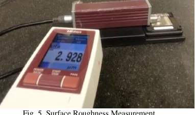
outcome of the several testing made on the surface of the specimens. The results are sometimes read by digitally and sometimes read in the form graphs and charts. In the present study SJ-310, aportable surface roughness tester of mitutoyo make (Fig.5) is used for direct reading of values on the specimens.
The RA values are determined with the help of SJ-310 instrument. A stylus tip of radius 0.0125 mm is used. The direction of measurement is made; in general, approximately at an angle of 900 to the „lay‟ and for each specimen, five readings for thicknesses of different cross-sections are taken at the positions that are not close to any edges.
Fig. 5. Surface Roughness Measurement
C. Coating / plating Thickness Measurement
Coating / plating thickness of the electroplated specimens is conducted as per IS: 5523-1983, RA 1999 standards. The standard adopted involves testing of specimens by either microsection method or by eddy current method, of which microsection (microscopic) method of coating thickness has been adopted in this research.
The microsection method usually involves cutting a section of the specimen at one or more points on the significant surface where a minimum thickness may be expected (Fig. 6). The sections are mounted by moulding in a suitable material such that the plated surface is perpendicular to the face which is to be prepared for examination. Proper care should be taken to ensure that the sections are rigidly held and there are no voids between the plated surface and the mounting material.
Fig. 6. Specimens Subjected For Microscopic Coating Thickness Analysis
The mounted sections are carefully prepared without damaging the plated edge until any part of the coating which cracks or flakes during the cutting process are removed. The coating thickness is then measured at the desired point on theexposed section using a metallurgical microscope with the
attached camera that helps in identifying the thickness of the plating.
D. Adhesion Testing
Measuring Adhesion by Tape Test (ASTM D3359) is one of the oldest and more commonly used methods for determining the adhesion of a coating system on a metal substrate. This method is widely used in the industry for adhesion testing and is also specified by Underwriters Laboratories for use with UL Standard 746 C. The reason for its popularity is simple. The ASTM D3359 test method is quick, inexpensive and relatively easy to perform.
In this cross-cut tape test, a grid is cut through the coating and into the substrate. A special adhesion tape (Thermacel #99) is used for this procedure. The tape is pressed onto the grid and rubbed with a pencil eraser. The tape is then pulled off rapidly with a smooth motion. The grid area is then inspected using an illuminated magnifier. The results of the test indicate an excellent adhesion of a coating system.
E. Salt Spray Test
Salt spray test is a method of testing ferrous and non-ferrous metals, organic and inorganic coatings, electroplated plastics, paints etc. The procedure is normally followed when the materials and product specifications are dependent on this test. Salt spray test is carried in accordance with ASTM B117. The salt spray test apparatus consists of a vat containing salt solution, a fog compartment, a channel to supply compressed air, nozzles to supply or spray the salt solution on the specimens. The specimens are hung between 15 and 30 degree from the vertical in the chamber. Careful observations are made to see that specimens and the salt solution do not come in contact with each other. The salt solution is made by mixing 95 parts of distilled water to 5 parts of sodium chloride (NaCl). NaCl is used as a salt that is free from nickel and copper and containing, on the dry basis, not more than 0.1 percent of sodium iodide and not more than 0.3 percent of total impurities.
The pH (salt solution) is maintained in such a way that when sprayed at 35 0C, the collected solution is in the pH range of 6.5 to 7.2. Before the solution is atomized, it is made free of suspended solids [12]. The results of the tests are as shown in the Table 1. The specimens used in the study have been shown in Fig. 7.
Fig. 7. Samples Subjected to Salt Spray Test
TABLE I.
DETAILS OF THE SALT SPRAY TEST ON THE ELECTROPLATED SAMPLES
F. Modified Drop Impact Test
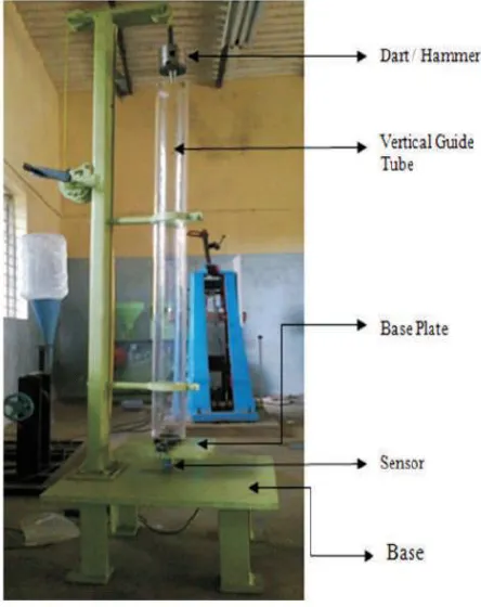
The drop impact test carried out in this research slightly differs from the ASTM D5628 standard. The drop impact testing machine used in this study was designed and developed by Mithun. V. Kulkarni et al., [13] for their work to study the impact resistance of polyamides.
Necessary
approval is obtained from them and tests are conducted in the R&D Department of Alpha College of Engineering, Bengaluru, India. The specially designed impact tester (Fig. 9) can be tested for low velocity testing‟s (testing speed < 10m/s). The impact tests are conducted by dropping the
hammer directly on the specimens from a height of 400mm and also by varying the drop weights by 0.89Kg, 1.395 Kg and 2.33 Kgs. The prepared specimens are of 50mm x 50mm x 4mm dimensions (Fig. 8).
Fig. 8. Hardness /Drop Impact Specimen
Figure 9: Drop Impact Tester [13]
G. Hardness Test
The term hardness has many definitions; yet does not have a perfect definition. Some may define it as resistance to scratch or as resistance to indentation or as resistance to deformation, but at the same time, hardness should not be confused with terms like wear and abrasion resistance of materials against the externally applied load.
Some plastic materials, for instance, polystyrene have lower abrasion resistance, but have high hardness (Rockwell). Therefore hardness is purely a relative term and is not measured in terms of mass / length / time. Hardness tests are also considered to be nondestructive tests (NDT) and are commonly used for quick quality check of a material. In the present days, since plastics are being used in many Sample Description
(Plated)
SAMPLES USED IN THE STUDY
ABS
Test Process
Standard Reference ASTM B117
Test Conducted Neutral salt spray test
Solution Used 5% NaCl solution
Temperature 35 0C ± 1 0C
Volume of Salt Solution
Collected 1.6 ml per hour in 80 cm
2
pH of Collected
Solution 6.75
Protection Used Nil
Specified Duration 24 hrs.
Result
Observation
No White rust observed during the
period of 24 hours
No Red rust observed during the
applications, measurement of their hardness also becomes important and many tests have been devised to measure the hardness of plastic.
Rockwell and the Durometer hardness tests are the most common tests performed on plastic materials. The Rockwell hardness test is usually carried on plastics such as polystyrene, nylons, acetals and acrylics where hardness is usually measured by knowing the penetration depth of the indenter due to the applied force. Rockwell Hardness is measured with scales ranging from A to V. Hardness of plastics is usually read on R scale, and higher the number, higher the hardness. On the other hand, Durometer hardness is carried on plastics such as polyethylene, Poly Vinyl Chloride (PVC) and thermoplastic rubbers, which are considered to be flexible materials.
Hardness test (Rockwell Hardness test) on ABS composites in plated and nonplated conditions is carried out in accordance with ASTM D785 standards. The Hardness test is performed by placing a standard specimen (Fig.9) of 4 mm thickness on the platform of the tester. The readings are directly taken from the dial indicator of the Rockwell hardness tester by applying the minor and major load.
V. RESULTS AND COMPARISON
All the specimens are tested for different drop weights and the data is recorded for each specimen. In the test, the dart or the Impactor was dropped from a height of 400 mm, and the drop weights used in the study are of 0.89 kg, 1.395 kg and 2.33 kg. For different Drop weights, the energy due to falling drop is calculated according to the kinetic energy relation (KE=0.5mV2).
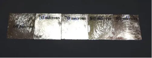
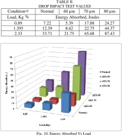
The specimens under study were classified into two types namely, Plated and nonplated. The plated specimens are plated with microns of 60, 70 and 80 respectively. From the Table 2, it is understood that, the 80 µm specimens show better resistance towards the impact loads followed by 70 µm and 60 µm specimens in comparison with the nonplated specimens.
This increase in the impact resistance can be attributed to the nickel layer that readily absorbs the energy and transfers it to its immediate copper layer and then to the base material. Similar observations were recorded by Mithun V Kulkarni et al. [14], in their work on, “Improvements in Impact Resistance Property of Metal Plated ABS and Nylon6 Thermoplastics”. They reported that, electroplated ABS specimens increased their energy absorption value by 143% in comparison to the normal ABS specimens (nonplated).
Similar observations have been reported in our work also, that is, the 80 µm specimens have shown an increase of 243%, followed by 70 µm specimens with an increase of 147 %. The 60 µm specimens have shown a decrease of 25% in strength. The possible reason for the decrease could be due to the reduced plating thickness that may not be able to transfer or absorb the energy.
Similarly, the specimens have shown improved resistance at higher loads of 1.395 Kg and 2.33 Kgs as shown in Fig. 10. This indicates that electroplated specimens can perform better over the normal ABS specimens, and thus the electroplated
specimens may find its usage in the development of structures for UAVs, as reported by U Chandrasekhar et al. [8]
TABLE II.
DROP IMPACT TEST VALUES
Condition Normal 60 µm 70 µm 80 µm
Load, Kg Energy Absorbed, Joules
0.89 7.22 5.39 17.88 24.27
1.395 12.39 8.62 22.75 44.37
2.33 33.71 21.75 65.68 87.43
Fig. 10. Energy Absorbed Vs Load
The Hardness tests are conducted as per ASTM D785 standards at Alpha College of Engineering, Bengaluru. Table 3 briefs about the results obtained from the tests. The table indicates that the electroplated specimens have shown a good improvement in the enhancement of the hardness. Nickel belongs to the transition metals and is hard [15] and ductile. This ability makes it an ideal material for electroplating of plastics. Nickel is also an excellent corrosion inhibitor. The combination of ductility and hardness gives the property to take the loads and builds the ability to resist the indentation.
TABLE III.
HARDNESS VALUES OF NORMAL AND ELECTROPLATED FDM ABS MATERIAL
Condition of FDM Samples
Materials
ABS 60 µm 70 µm 80 µm
Normal 95 -- -- --
Electroplated -- 101 103 107
Rockwell hardness, HRR
CONCLUSION
The limitations faced by FDM prototypes with respect to strength have been overcome with the usage of electroplating technique.
The electroplating also tends to give smooth surface of FDM parts.
The hardness of the electroplated specimens has increased by 6.3%, 7.7 % and 11.2% with 60, 70 and 80 µm specimens respectively, as compared with nonplated ABS specimens.
80 µm impact test specimens have shown an increase of 243%, followed by 70 µm specimens with an increase of 147 %. The 60 µm specimens have shown a decrease of 25% in strength. This indicates that the higher coating thickness has increased the impact resistance of FDM-ABS materials.
REFERENCES
[1] Masood. S.H. Intelligent rapid prototyping with fused deposition
modelling. Rapid Prototyping Journal, 1996;2(1):24–33.
[2] Masood S.H., Song W.Q., Development of new metal/polymer
materials for rapid tooling using Fused deposition modelling, Materials and Design, 2004, 25: 587–594
[3] Kumar .S, Kruth. J.P., Composites by rapid prototyping
technology, Materials and Design, 2010, 31: 850–856.
[4] Agarwala MK, Van Weeren R, Bandyopadhyay A, Whalen PJ,
Safari A, Danforth SC. Fused deposition of ceramics and metals: An overview. In: Proceedings of Solid Freeform Fabrication Symposium, The University of Texas, Austin 1996. p. 385–392.
[5] Bandyopadhyay A, Panda RK, Janas VF, Danforth SC, Safari A.
Processing of piezocomposites by fused deposition techniques. Journal of the American Ceramic Society 1997; 80(6):1366– 1372.
[6] Mithun V Kulkarni, Elangovan K, Hemachandra Reddy K,
Effects of Electroplating on the mechanical properties of Injection molded Thermoplastics, International Journal of Plastics Technology (December 2013), 17(2):163–170, DOI: 10.1007/s12588-013-9056-6.
[7] Zhou .Z, D Li, J Zeng and Z Zhang, Rapid fabrication of
metal-coated composite stereolithography parts, Proc. IMechE Vol. 221 Part B: J. Engineering Manufacture, 2007, 1431 - 1440
[8] Chandrasekhar. U, Venkatesh. K, Elangovan. K, Rangaswamy.
T, Integrated Use of Rapid Prototyping and Metal Plating Techniques For Development of Micro Air Vehicles, International Journal of Engineering Science and Technology, 3(1), 2011, pp:188-193.
[9] Parkinson R, Plating on Plastics - An Industry Review. Plating
& Surface Finishing, 1994, 81: 32-35.
[10] Mithun V Kulkarni, Elangovan. K, Hemachandra Reddy .K,
Development of electroplating process for plating polyamides, Bangladesh J. Sci. Ind. Res. 48(3), 205-212, 2013.
[11] Broniewski. T, Kapko. J, Placzek. W, and Thomalla. J Testing
and assessment of the properties of plastics. Warsaw: Science and Technology, 2000.
[12] Sukumaran. J, Rodriguez. V, De Baets.P; Perez. Y; Ando. M;
Dhieb. H; and Neis.P A review on water lubrication of polymers. 4th Conference on Sustainable Construction and Design. Ghent, Belgium, 2012.
[13] Mithun V Kulkarni, Elangovan. K, Hemachandra Reddy. K,
Prakash J N, Investigations of the influence of filler on the impact properties of polyamides and its composites,
i-manager‟s Journal on Mechanical Engineering, l (4) August - October 2011, 1-6
[14] Mithun V Kulkarni, Elangovan. K, Hemachandra Reddy,
Improvements in Impact Resistance Property of Metal Plated ABS and Nylon6 Thermoplastics, FS Journal of Engineering Research, Vol 1(1), 2012, pp 31-33.
[15] http://en.wikipedia.org/wiki/Nickel (accessed on 03-06-2014)
[16] D. T. Pham, S. S. Dimov, Rapid manufacturing,