145804-3737-IJMME-IJENS © August 2014 IJENS I J E N S
Abstract-- An experimental study is carried out to investigate the effects of nozzle aspect ratio and hot tube length on the energy separation of a Ranque-Hilsch vortex tube (RHVT). The inlet pressures were adjusted from 200 kPa to 600 kPa with 100 kPa increments. A dry air is used as the working fluid. The conventional tangential nozzle (N = 6) was used. The inner diameter (D) of vortex tube used in the experiments was 7.5 mm. The ratio of the length of the vortex tube to its diameter (L/D) varied from 10 to 30. The experimental results reveal that the nozzle aspect has a great effect on energy separation. The results show that the maximum differences in temperature of hot and cold streams were obtained for the aspect ratio of 1.4.
Index Term-- Ranque-Hilsch - Con- flow vortex tube, Aspect ratio, Energy separation.
NOMENCLATURE
AR Aspect ratio, [-]
B Width of each nozzle, [m]
D Inner diameter of vortex tube, [m] d Diameter of cold orifice plate, [m] L Length of the tube, [m]
m Mass flow rate, [kg/s] N Number of nozzle P Pressure, bar T Temperature, [˚C] CF Cold fraction, [-]
W Height of each nozzle [m]
Subscript c Cold h Hot i Inlet
1. INTRODUCTION
The vortex tube is a simple device operating as a refrigeration machine without any moving part e.g. rotating shaft or piston cylinder [1]. It is consisted of nozzle (s), vortex chamber, separating cold plate, hot and cold end tubes [2]. The vortex tube was first discovered by Ranque [3, 4], who was granted a French patent for
1 Faculty of Engineering, Mechanical Power Department, South Valley
University, Qena – Egypt.
2
Mechanical Department, Faculty of Industrial Education, Sohag University, Sohag – Egypt.
3 Qarun Petroleum Company, Egypt
* Corresponding Author: M. Attalla, email: [email protected]
the device in 1932 and a United States patent in 1934. In 1945, Rudolf Hilsch [5] was conducted an experiment on vortex tube that focused on the thermal performance with different geometrical parameters.
The vortex tube or RHVT can be classified into two types; first is counter flow RHVT and second type is uni-flow RHVT [6]. In the counter-flow vortex tube type the cold flow move in the opposite direction with respect to the hot stream, while in the uni-flow type, the hot and cold stream flow in the same direction as shown in Fig. 1. In general, the counter-flow RHVT was recommended more the uni-flow RHVT for its efficient energy separation. The RHVT is widely applied for cooling and heating applications. The major application is for cooling purpose, e.g. cooling of electric device, cooling of machinery during operation. In spite of its small capacity, the vortex tube is very useful for certain application because it is simple, compact, light, and require no refrigerant [7, 8].
In the recent years it was known that vortex tube is a low cost and an effective solution for many spot cooling problems. The separation mechanism inside the vortex tube remains today not completely understood [9]. Up to date, more than hundred investigations on the energy separation in the RHVT for both numerical and experimental works have been published [10]. For numerical study, numerous investigators have conducted the energy separation in the RHVT by using turbulence modeling. Frohlingsdorf and Unger [11] used the computational code based on CFX along with k-ε model investigated the energy separation inside the vortex tube. Behera et al. [12] used the CFD cod (Star-CD) to investigate the temperature separation in vortex tube. In their study, the effect of the secondary circulation and length of the hot tube on energy separation were also calculated. Shamsoddini and Nezhad [13] were studied the effect of the nozzle number on the flow and power of cooling process of a vortex tube using a three dimensional numerical fluid flow dynamic model. Eiamsa-ard and Promvonge [14] studied numerically the energy separation in a uni-flow vortex tube using k-ε model. They concluded that the maximum temperature gradients appear in the outer regions close to the tube wall and the separation effect in the core region near the inlet nozzle. Farouk and Farouk [15] used large eddy simulation method to predict the flow and temperature field in the vortex tube. Farouk et al. [16] computed the temperature and flow field of the species mass fraction in counter-flow vortex tube with nitrogen and helium as a working fluid. The artificial neural networks and employing the experimental data were used to predicate the effect of length to diameter ratio and nozzles
M. Attalla
1*, M. Salem
2& A. Abo EL-Wafa
3An Experimental Investigation of the Optimum
Geometry for Energy Separation of the
145804-3737-IJMME-IJENS © August 2014 IJENS I J E N S
number on performance of counter-flow RHVT by Dincer et al. [17].
In same time with the numerical works, many experimental investigations have been completed to study the performance of the vortex tube. Here, some of the experimental works on temperature separation in the vortex tube are explained as follows.
Hot Air Out Cold Air
Nozzle
Air Inlet
Orifice Plate
Conce Valve Air Inlet
(a)
Air Inlet
Air Inlet
Cold Air Out Hot Air Out
Conce Valve Nozzle
Air Inlet
(b)
Fig. 1. Basic typed of Ranque-Hilsch Vortex Tube: (a) Counter Flow and (b) Parallel Flow [1].
Salid and Valipour [18] investigated the influence of the RHVT diameter and hot tube length, number of nozzle on the cold temperature difference in a counter-flow vortex tube. They observed that the maximum cold air temperature difference was found at tube length to vortex diameter ratio ranged from 20 to 55.5, and cold orifice diameter ratio, β = 0.5, with the used of helium as the working fluid. Dincer et al. [19] studied the effects of control valve geometry, plug location and number of nozzle on energy separation under different inlet pressure. Valipour and Niazi [20] investigated the effects of axial curvature and turning angle of main tube on the efficiency of vortex tube under different inlet pressure.
Wu et al. [2] presented the effect of the conventional nozzle, proposed nozzle and nozzle of Archimedes on the energy separation of vortex tube. Their results observed that the enhanced nozzle provided a better cooling performance with temperature of cold gas of about 2.2 ˚C and 5 ˚C lower than those presented by the nozzle with a normal rectangle and the with Archimedes coil, respectively. The effect of generator vortex angle of rotating flow on the performance of the RHVT was studied by Xue and Arjomandi [21]. They showed that the maximum cooling efficiency was obtained between vortex generator angles of 4.8 and 6.7˚. Kirmaci [22] investigated the effects of the nozzle numbers and inlet pressures on the energy separation of vortex tube using air and oxygen as working fluids. It observed that the temperature rise between hot and cold fluid reduces with increasing nozzle number. In addition, the cold temperature reductions for using both two working fluids (air and oxygen) increase with the increase of the inlet pressure. The experimental work of Hamdan et al. [8, 23] reported the effect of nozzle parameters on the energy separation of the vortex tube. Their results indicated that the maximum energy separation was achieved with tangential nozzle orientation while the symmetry/asymmetry of nozzles has a minimal effect on the performance of the energy separation.
Singh et al. [24] reported the effect of different parameters such as nozzle number, hot end area and mass fractions on the performance of RHVT. They showed that the effect of nozzle geometry was more important than the cold orifice design in getting high temperature separations. Gao et al. [25] used a special pitot tube and thermocouple techniques to measure the pressure, velocity and temperature distribution inside the vortex tube which the pitot tube has only a diameter of 1 mm with one hole. They observed that rounding off the entrance can be improved and extended the secondary circulation gas flow and enhanced the system performance. Aydin and Baki [7] studied experimentally the temperature separation in a counter-flow vortex tube with various geometrical and thermo-physic parameters. In their work the geometry of tube was optimized to maximum the temperature difference between the inlet and cold temperatures by changing the various dimensions of the tube such as the diameter of the inlet nozzle and the angle of the control valve.
From the above cited literature clearly indicated that the energy separation and the efficiency of a vortex tube are significantly affected by the various geometrical parameters. The present study is experimentally investigated and conducted to provide some new insight into the energy separation of the vortex tube under different operating parameters. Effect of aspect ratio (AR = 2.4, 1.6, 1.4, 0.8, and 0.6), inlet pressure (Pi = 600, 500, 400, 300, and 200) kPa, and cold mass fractions (CF = 0.4 to 0.9) on energy separation were experimentally studied.
2. EXPERIMENTAL STUDY
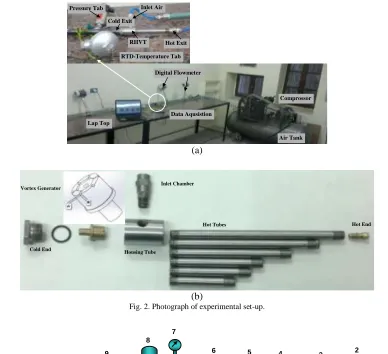
RTD-Temperature Tab
RHVT Hot Exit
Cold Exit
Pressure Tab Inlet Air
Comprossor
Air Tank Lap Top
Digital Flowmeter
Data Aqusistion
(a)
Hot Tubes
Housing Tube Vortex Generator
Hot End
Cold End
Inlet Chamber
(b)
Fig. 2. Photograph of experimental set-up.
1 2
3 4
5 6
7
7 7
8
8 8
9 9
9 10
1. Compressor. 2. Pressure tank. 3. Valve. 4. Dehumidifying. 5. Filter. 6. Pressure regulator. 7. Pressure tab. 8. RTD unit. 9. Digital flow meter. 10. RHVT.
Fig. 3. Schematic diagram of the experimental set-up
Working fluid was compressed air provided by a two stage reciprocating compressor (800 kPa, 1.3 m3/min, 7.5/10 kW/Hp). The compressed air reached to the vortex tube after passing through a dehumidifier device and a filter. Inside the vortex tube, the working fluid was separated into two streams with low and high temperatures. The cold air stream leaves the tube through the central of the vortex generator (cold exit), while the hot air stream at the periphery exhausts out of the other exit (hot exit). The mass flow rates of the inlet air and the cold air discharge were measured by digital flow meter (Model: LUGY-15). The cold mass fraction (CF) was attended by the cone-shaped valve. The cold air temperature was measured at the exit of the cold air tube while the hot air temperature was measured. All of the temperatures data were measured by using RTD (RTD – Model: TX251) and recorded with a multiple data acquisition unit. The inlet pressure and pressure through the cold stream were measured using
pressure transducer (Danfoss - Model: AKS-33), as shown in Fig. 3.
3. DATA REDUCTION
The hot stream temperature difference ΔTh and the cold
stream temperature difference ΔTc are the keys displayed of
the temperature separation process in the RHVT which can be expressed as follows, respectively:
c i
c T T
T
(1)
i h
h T T
T
(2) Where Ti is the inlet air temperature, Tc is cold air temperature
and Th is the hot air temperature. The other important
parameters governing the energy separation is the cold mass fraction, CF. It is defined as the ratio of the cold air to the inlet air mass flow rates:
i c m m CF
(3)
In general, the performance of the vortex tube is defined as the difference between the heating effect and the cooling effect which can be obtained as follows [10]:
c
h T
T
T
(4)
4. RESULTS AND DISCUSSION
In the present work, the effects of nozzle aspect ratio and hot tube length on temperature separation are investigated experimentally. For this purpose, six set of hot tube length to vortex diameter (L/D) varied from 10 to 30 one vortex generator with 6 nozzle number having the five aspect ratio of AR = 2.4, 2.6, 1.4, 0.8, and 0.6 are tested under different inlet pressures.
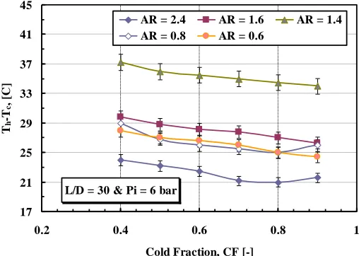
4.1 Effect of Aspect Ratio
The temperature difference between the hot and cold stream (ΔT) as a function of cold mass fraction with different aspect ratio were shown in Fig. 4 to Fig. 7. The ΔT decreases with increasing of CF in all values of aspect ratios. This result can be considered as an aiding or an opposing effect of interaction between the viscous resistance and acceleration of the hot and cold stream. In view of the maximum temperature difference, the data obtained obviously showed that the aspect ratio has a significant effect on temperature separation. These figures were observed that the maximum temperature difference obtained for aspect ratio of 1.4. This result can be attributed to the back flow mechanism occurred near the cold exit of the vortex tube for aspect ratio of 1.4. These results were compatible with those of Avci [10], where they proofed that the ΔT decreases with increasing of nozzle AR. Where the increasing of aspect ratio leads to larger mixing zones and the certain amount of inlet stream directly flows back to the cold exit and mixes with the cold stream. In addition an increases in AR leads to large mixing zones where the certain amount of inlet stream directly flows back to the cold exit and mixes with the cold stream and, in follows, results in a decrement in the temperature difference between the hot and cold stream while the opposite is true for lower values of AR.
Figure 4 showed that the maximum temperature differences for inlet pressure of 6 bar with aspect ratios of 1.4, 1.6, and 2.4 are 37.24 ˚C, 29.8 ˚C, and 29 ˚C, respectively. These results also disclose that the temperature separation increases with
increasing in Pi as shown in Figs. 5-7. These results can be
elucidated by the chocking of the flow. When the inlet pressure is increased, the velocity of flow outside the nozzle increases. After the chocking takes place, velocity and mass flow rate outside of the inlet nozzle don’t increase any more, even though inlet pressure increases [10].
L/D = 30 & Pi = 6 bar
17 21 25 29 33 37 41 45
0.2 0.4 0.6 0.8 1
Cold Fraction, CF [-]
T
h
-T
c
, [
C]
AR = 2.4 AR = 1.6 AR = 1.4
AR = 0.8 AR = 0.6
Fig. 4. Effect of the aspect ratio on temperature separation in a RHVT for Pi=6 bar.
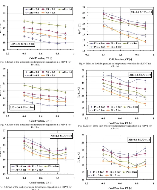
4.2 Effect of Inlet Pressure
Figure 8 to Figure 12 shows the variation of the cold mass fraction (CF) against the temperature different (Th-Tc). These
results are obtained for different aspect ratio (AR = 2.4, 1.6, 1.4, 0.8 and 0.6) and one set of hot tube length ratio (L/D = 10). For all the set of runs, the energy separation considerably maximum value at cold mass fraction (CF = 0.4). In addition, increasing the inlet pressure (Pi) of the counter-flow
Ranque-Hilsch vortex tube has increased the temperature gradient between the hot and the cold outlets. This due to the fact that at high pressure, air enters the RHVT with a higher tangential velocity, resulting in higher momentum transfer from the central region of the tube to the tube wall. This offers a better temperature separation, providing a higher temperature at the tube surface and a lower temperature in the core region of the tube.
L/D = 30 & Pi = 4 bar
15 19 23 27 31 35 39
0.2 0.4 0.6 0.8 1
Cold Fraction, CF [-]
Th
-T
c
, [
C]
AR = 2.4 AR = 1.6 AR = 1.4
AR = 0.8 AR = 0.6
L/D = 30 & Pi = 3 bar
15 19 23 27 31 35 39
0.2 0.4 0.6 0.8 1
Cold Fraction, CF [-]
Th
-T
c
, [
C]
AR = 2.4 AR = 1.6 AR = 1.4
AR = 0.8 AR = 0.6
Fig. 6. Effect of the aspect ratio on temperature separation in a RHVT for Pi=3 bar.
L/D = 30 & Pi = 2 bar
15 19 23 27 31 35 39
0.2 0.4 0.6 0.8 1
Cold Fraction, CF [-]
Th
-T
c
, [
o C]
AR = 2.4 AR = 1.6 AR = 1.4
AR = 0.8 AR = 0.6
Fig. 7. Effect of the aspect ratio on temperature separation in a RHVT for Pi=2 bar.
AR=2.4 & L/D = 10
15 17 19 21 23 25 27
0.2 0.4 0.6 0.8 1
Cold Fraction, CF [-]
Th
-T
c
,
[C
]
Pi = 6 bar Pi = 5 bar Pi = 4 bar
Pi = 3 bar Pi = 2 bar
Fig. 8. Effect of the inlet pressure on temperature separation in a RHVT for AR=2.4.
AR=1.6 & L/D = 10
13 15 17 19 21 23 25 27 29
0.2 0.4 0.6 0.8 1
Cold Fraction, CF [-]
T
h
-T
c
,
[C
]
Pi = 6 bar Pi = 5 bar Pi = 4 bar
Pi = 3 bar Pi = 2 bar
Fig. 9. Effect of the inlet pressure on temperature separation in a RHVT for AR=1.6.
AR=1.4 & L/D = 10
15 17 19 21 23 25 27 29
0.2 0.4 0.6 0.8 1
Cold Fraction, CF [-]
Th
-T
c
, [
C]
Pi = 6 bar Pi = 5 bar Pi = 4 bar
Pi = 3 bar Pi = 2 bar
Fig. 10. Effect of the inlet pressure on temperature separation in a RHVT for AR=1.4.
AR=0.8 & L/D = 10
11 13 15 17 19 21 23
0.2 0.4 0.6 0.8 1
Cold Fraction, CF [-]
Th
-T
c
, [
C]
Pi = 6 bar Pi = 5 bar Pi = 4 bar
Pi = 3 bar Pi = 2 bar
AR=0.6 & L/D = 10
9 11 13 15 17 19 21 23 25
0.2 0.4 0.6 0.8 1
Cold Fraction, CF [-]
Th
-T
c
, [
C]
Pi = 6 bar Pi = 5 bar Pi = 4 bar
Pi = 3 bar Pi = 2 bar
Fig. 12. Effect of the inlet pressure on temperature separation in a RHVT for AR=0.6.
Also, the flow velocity in the outlet of the entrance nozzle is increased by increasing the inlet pressure up to the point that chocking of the flow takes place. Since then the temperature gradient increases as the pressure goes up more. In the range studied, the maximum temperature differences at pressure of 600 kPa and 500 kPa are 27.6 ˚C and 26 ˚C for AR of 1.4 and L/D of 10 respectively as shown in Fig. 9 and Fig. 10.
From these figures observed that the temperature separation increases with decreases of aspect ratio (AR) in range of 2.4 and 1.6 and reach the maximum value at the aspect ratio of 1.4. Above the aspect ratio of 1.4 the energy separation was decrease.
4.3 Effect of Hot Tube Length
The effect of hot tube length on temperature separation was observed in Figs. 13 to 15. These figures shows the temperatures gradients between the hot stream and cold stream outlet as a function of cold mass frication, (CF) at different aspect ratio for six different lengths of vortex tube ratio, L/D = 10, 13, 15, 20, 25, and 30. For variable tube length the inlet pressure and number of nozzle was kept constant 6 bar and 6 nozzles respectively. It is presented that the temperature difference for various length of hot tubes has a relative small difference at CF ≤ 0.5 for two values of AR of 1.6 and 0.6 as shown in Figs. 13 and 14. The experimental results indicate that the length of hot tube has little effect on temperature difference at CF ˃ 0.4.
From the figures it can be noted that for aspect ratio of 2.4, the maximum temperature gradient was given at L/D of 25 as shown in Fig. 13. While for the aspect ratio less than 2.4, the maximum temperature gradient was obtain at L/D of 30 as shown in Fig. 14 and Fig. 15. But for all values of L/D, the temperature different between hot and cold stream decreases with increase of cold mass fraction CF. on the basis of the conclusion made by Chang et al. [28] for vortex tube with a cylinder tube, there is a critical length of vortex tube over which majority of the energy transfer takes place. Consequently, the energy separation increase as the length of hot tube increases to a critical length, however a further increase of the hot tube length beyond the critical does not
improve the energy separation. It presents that the critical length to the diameter ratio (L/D) is ranged from 25 to 30 under our experimental conditions.
AR=2.4 & Pi=6 bar
15 18 21 24 27 30
0.2 0.4 0.6 0.8 1
Cold Fraction, CF [-]
Th
-T
c
, [
C]
L/D=10 L/D=13 L/D=15
L/D=20 L/D=25 L/D=30
Fig. 13. Effect of the hot tube length on temperature separation in a RHVT for AR=2.4.
AR=1.6 & Pi=6 bar
20 25 30 35
0.2 0.4 0.6 0.8 1
Cold Fraction, CF [-]
Th
-T
c
, [
C]
L/D=10 L/D=13 L/D=15
L/D=20 L/D=25 L/D=30
Fig. 14. Effect of the hot tube length on temperature separation in a RHVT for AR=1.6.
AR=0.6 & Pi= 6 bar
15 20 25 30 35
0.2 0.4 0.6 0.8 1
Cold Fraction, CF [-]
Th
-T
c
, [
C]
L/D=10 L/D=13 L/D=15
L/D=20 L/D=25 L/D=30
5. CONCLUSION
In this study, the experimental data has been obtained for a counter-flow Ranque-Hilsch vortex tube having number of nozzle (N = 6); L/D = 10, 13, 15, 20, 25, and 30, with inlet pressure varied from 200 kPa to 600 kPa. The maximum temperature separation was obtained with aspect ratio of vortex tube ranged from 2.4 to 0.6. The cold mass fraction was varied from 0.4 to 0.9. All of the experimental results can be drawn as follows:
The nozzle geometry (aspect ratio) has a considerable effect on temperature separation mechanism. The optimum value of temperature difference was achieved at aspect ratio of 1.4 and it is found to be 37 ˚C for the inlet pressure of 600 kPa.
It is clear that the inlet pressure is the necessary driving force for energy separation. The experiments show that the highest temperature reduction will be obtained at highest inlet pressure.
The experimental shown that the cold fraction is an important parameter influencing the performance of the temperature separation in the vortex tube. The optimum value of temperature reduction was founded at cold fraction of 0.4.
The vortex tube length to diameter ratio has a different significant effect on the energy separation process. The vortex tube to diameter ratio L/D = 30 with aspect ratio AR = 1.4 and 0.6, the temperature reduction is 28˚C and 37.5˚C at inlet pressure of 600 kPa respectively. While the temperature separation was 27˚C when L/D = 25 and aspect ratio AR = 2.4.
ACKNOWLEDGEMENTS
Financial support of this study by the research found of the South Valley University under Grant 2014/134/126-E is gratefully.
REFERENCES
[1] S. Eiams-ard, P. Promvonge, Review of Ranque-Hilsch effects in vortex tube, Renewable & Sustainable Energy Review, 12, 1822-1842, 2008.
[2] Y. T. Wu Y. Ding, Y. B. Ji, C. F. Ma, M. C. Ge, Modification and experimental research on vortex tube, International Journal of Refrigeration, 20, 1042-1049, 2007.
[3] G. J. Ranque, Experimental on expansion in a vortex with simultaneous exhaust of hot air and cold air, Journal Physics Radium (Paris), 4:112-114 S-115, Jun, 1933.
[4] G. J. Ranque, Method and apparatus for obtaining from a fluid under pressure two outputs of fluid at different temperature, US patent, 1:952,281, 1934.
[5] R. Hilsch, the use of expansion of gases in a centrifugal field as a cooling process, Rev Sci Instrum, 18-2:108-13, 1947.
[6] S. Eiams-ard, K. Wongcharee, P. Promvonge, Experimental investigation on energy separation in a counter-flow Ranque-Hilsch vortex tube: Effect of cooling a hot tube, International Journal Communications in Heat and Mass Transfer, 37, 156-162, 2010.
[7] O. Aydın, M. Baki, An experimental study on the design parameters of a counter-flow vortex tube, Energy Journal, 31, 2763-2772, 2006.
[8] A. Quadha, M. Baghdad, Y. Addad, Effect of variable thermophysical properties on flow and energy separation in a vortex tube, International Journal of Refrigeration, 36, 2426-2437, 2013.
[9] M. O. Hamdan, B. Alsayyed, E. Elnajjar, Nozzle parameters affecting vortex tube energy separation performance, Heat Mass Transfer Journal, 49, 533-541, 2013.
[10] M. Avci, The effect of nozzle aspect ratio and nozzle number on the
performance of the Ranque-Hilsch vortex tube, Applied Thermal Engineering Journal, 50, 302-308, 2013.
[11] W. Frohlingsdorf, H. Unger, Numerical investigation of the compressible flow and energy separation in Ranque-Hilsch vortex tube, International Journal of Heat and Mass Transfer, 42, 415-422, 1999.
[12] U. Behera, PJ. Paul, K. Dinesh, S. Jacob, Numerical investigation on flow and temperature separation in Eanque-Hilsch vortex tube, International Journal of Heat and Mass Transfer, 51, No, 25-26, 6077-6089, 2008.
[13] R. Shamsoddini, A. H. Nezhad, Numerical analysis of the effects of nozzle number on the flow and power of cooling of a vortex tube, International Journal of Refrigeration, 33, 774-782, 2010.
[14] S. Eimsa-ard, P. Promvong, Numerical simulation of flow field and temperature separation in a vortex tube, International communication in Heat and Mass Transfer, 35,No. 8, 937-947, 2008.
[15] T. Farouk, B. Farouk, Large eddy simulation of the flow field and temperature separation in the Ranque-Hilsch vortex tube, International Journal of Heat and Mass Transfer, 50, No. 23-24, 4724-4735, 2007.
[16] T. Farouk, B. Farouk, A. Gutsol, Simulation of gas species and temperature separation in the counter-flow Ranque-Hilsch vortex tube using large eddy simulation technique, International Journal of Heat and Mass Transfer, 52, 3320-3333, 2009.
[17] K. Dincer, S. Tasdemir, S. Baskaya, B. Z. Uysal, Modeling of the effects of length to diameter ratio and nozzle number on the Performance of the counter-flow Ranque-Hilsch vortex tubes using artificial neural network, Applied Thermal Engineering, 28, 2380-2390, 2008.
[18] M. H. Saidi, M. S. Vaalipour, Experimental modeling of vortex tube refrigeration, Applied Thermal Engineering, 23, 1971-1980, 2003.
[19] K. Dincer, S. Baskaya, B. Z. Uysal, I. Ucgul, Experimental investigation of the performance of a Ranque-Hilsch vortex tube with regard to a plug located at the hot tube, International Journal of Refrigeration, 32, 87-94, 2009.
[20] M. S. Valipour, N. Niazi, Experimental modeling of curved Ranque-Hilsch vortex tube refrigeration, International Journal of Refrigeration, 34, 1109-1116, 2011.
[21] Y. Xue, M. Arjomandi, The effect of vortex angle on the efficiency of the Ranque-Hilsch vortex tube, Experimental Thermal Fluid Sci., 33, 54-57, 2008.
[22] V. Kirmaci, Exergy analysis and performance of a counter flow Ranque-Hilsch vortex tube having various nozzle numbers at different inlet pressure of oxygen and air, International Journal of Refrigeration, 32, 1626-1633, 2009.
[23] M. O. Hamdan, A. Alawar, E. Elnajjar, W. Siddique, Eperimental analysis on vortex tube energy separation performance, Heat Mass Transfer Journal, 47, 1637-1642, 2011.
[24] P. K. Singh, An experimental performance evaluation of vortex tube, IE(I) J-MC, 84, 149-153, 2004.
[25] C. M. Gao, K. J. Bosschaart, J. C. H. Zeegers, A. T. A. M. Waele, Experimental study on a simple Ranque-Hilsch vortex tube, Gryogenics, 45, 173-183, 2005.
[26] ANSI/ASME, Measurement uncertainty, PCT 19: 1-1985 part I: 1986.
[27] R. B. Abernethy, R. P. Benedict, R. B. Dowdell, ASME measurement uncertainty, Journal of Fluid Engineering, 107, 161-164, 1985.
![Fig. 1. Basic typed of Ranque-Hilsch Vortex Tube: (a) Counter Flow and (b) (b) Parallel Flow [1]](https://thumb-us.123doks.com/thumbv2/123dok_us/1364648.1645904/2.595.46.286.150.282/basic-typed-ranque-hilsch-vortex-tube-counter-parallel.webp)
![Fig. 12. Effect of the inlet pressure on temperature separation in a RHVT for Cold Fraction, CF [-]AR=0.6](https://thumb-us.123doks.com/thumbv2/123dok_us/1364648.1645904/6.612.312.566.529.712/effect-inlet-pressure-temperature-separation-rhvt-cold-fraction.webp)
