Portable Power Generating Floor Boards
Balansay, Maria Lourdes V., Banaag,Mark Kevin, Ilagan, Anjho Antonio B., Maputi, Mariel M.
Batangas City, Philippines [email protected]
Batangas City, Philippines [email protected]
Batangas City, Philippines [email protected]
Batangas City, Philippines [email protected]
Abstract: The project will harvest energy by transforming mechanical energy to electrical energy with the mechanical energy coming from the footstep of people walking on it. When piezoelectric material was placed under mechanical stress, a shifting of the positive and negative charge centers in the material takes place, which then results in an external electrical field.The alternating current produced was then rectified using a full wave bridge rectifier which was then stored in a battery. The primary characteristic of the prototype was that it is portable with dimensions of 60 cm by 80 cm. This project could be an emergency power supply in times of power outage and good for the environment because it uses renewable power source.
Keywords: Piezoelectric, charge centers, Full wave bridge rectifier, emergency power supply
Introduction
Competition for energy resources grows at an unprecedented rate as resources are consumed, and as time goes by, tons and tons of resources are utilized to meet the demands of humanity; as a result, resources are vastly depleted. The possibility of an oil reserve in the West Philippine Sea and the Chinese aggression causes growing tension in the disputed islands. Increase in population causes the demand for electricity to mobilize in an increasing manner. WESM or Wholesale Electricity Spot Market provides real time view on the supply and demand of electricity. Because of this, more resources such as coal and oil are consumed. Alternative energy sources are employed to reduce the problem of pollution and the limited supply resources. Basically, many models are being carried out to generate electricity on local basis. Through these concepts, the electricity produced can be utilized by the locality. Alternative energy sources are employed to reduce the problem of pollution and the limited supply resources. Basically, many models are being carried out to generate electricity on local basis. Through these concepts, the electricity produced can be utilized by the locality. As a concerned citizen, the researchers are aware about the shutdown of the Malampaya Power Plant which will cause power shortage in the country. Although there are few other power plants that can produce extra source, the cost of these extra source will be much higher than usual, making it not economical to the people. With a problem like this that people face, renewable energy will be a great help to the shortage of power and economic status. With shortage of energy resource and the effect of climate change, clean, green and renewable energy resources are better options. This is because the usage of non-renewable resources continues to consume the earth’s resources and future generations may not be able to meet the energy demands because of the shortage of resource. One energy source considered in this study is use of piezoelectricity. Piezoelectricity is the electric charge that accumulates in
certain solid materials in response to applied mechanical stress. One of the unique characteristics of the piezoelectric effect is that it is reversible, meaning that materials exhibiting the direct piezoelectric effect also exhibit the converse piezoelectric effect. When piezoelectric material is placed under mechanical stress, a shifting of the positive and negative charge centers in the material takes place, which then results in an external electrical field. When reversed, an outer electrical field either stretches or compresses the piezoelectric material. The researchers were aware about the insufficient lighting system on the right and left entries on the CEAFA building due to busted lights. With this problem, students and faculty members in night classes experience inconvenience as they walk along the dark stairs light. The researchers thought of a solution to help generate alternative source of renewable energy that would at least supply power to small loads such as LED bulbs. A portable power generating floor board is a technology that can be used as a temporary power supply during power failure or if there is a need for a power supply. This is a portable device that can be placed in areas understanding of piezoelectric energy harvesting will pave the way for its acceptance as a desirable alternative solution for inexhaustible power source.
Objectives
The main objective of this study was to design and develop portable power generating floor boards. Specifically, the project sought to attain the following objectives:
1. To evaluate the existing footstep - powered generation in terms of the following:
1.1 design 1.2 construction 1.3 operation
2. To determine the project’s design requirements and
considerations:
2.1 Philippine Electrical Code (PEC)
2.2 Institute of Electrical and Electronics Engineers (IEEE)
2.3 National Electrical Manufacturers Association (NEMA)
3. To prepare the design plans in terms of: 3.1 general description of the project 3.2 design computation and analysis 3.3 design layouts
3.4 circuit diagram
3.5 bill of materials and specification 4. To present the financial study in terms of:
4.1 operating cash requirements 4.2 project cost evaluation
5. To determine the methods of fabrication and assembly: 5.1 materials/tools
5.2 methods
6. To determine the methods of testing in terms of operating characteristics as to sensitivity, charging and discharging:
6.1 procedure
6.2 results and discussion
7. To determine the contribution of the project to society and economy.
Materials and Methods
The project study used engineering and planning type of research accompanied by the use of plans, procedures, experiments and strategies to come up with the working prototype. Documentary analysis and field research were undertaken for clarification about the project study. The internet was used for data gathering of information for the existing system. Review of some related literature about the capabilities and flows of their project were done to come up with the distinct project. Also, the researchers studied the concepts and principles of operation of piezoelectric effect as the base for its suitability. Experiments such as the sensitivity, charging and discharging tests were used to test the functionality and efficiency of the project study. The factors that covers the condition of the project were also studied the opening condition of the project study. The following tests were done for generation of the expected energy in the sensitivity test, the researchers had to find for volunteers to measure their weight and then the sensitivity of the piezoelectric sensor was tested. The charging and discharging tests were utilized to check and monitor the condition of the battery after charging and after discharging using three different loads. When the information and data had been gathered and evaluated planning and construction of the prototype were followed. Design procedures started with the studying of a prototype that utilized human energy for small scale applications. Preparation on this appropriate design was strictly followed since it involved important processes such as lay outing and drafting of the device schematic diagram and layouts. The estimation of the cost was computed covering components and materials.
Results and Discussion
1.1 Evaluation of Existing Footstep-Powered Charger
1.1.1 Design. Initiated on 2014, in the students of Batangas State University designed and developed a combined piezoelectric energy harvesting system installed at the entrance gate of the university. The energy harvesting system aimed to harness energy from pedestrians and vehicles. The project was intended to lessen the power consumption of the university by supplying the pathway lightings using piezoelectric energy. The project harvested energy through the use of vibration motion or kinetic energy from pedestrians and vehicles crossing to produce electricity. The electrical parts of the project consisted of a 12 Volts dc generator which produces 12v controlling, 100W power inverter and a 12 volts battery bank. The proponents of the project used AWG No. 14 connection wire.12-24 volts 10A charge controller was used to limit the rate, at which electric current was added, and to prevent overcharging and protect against overvoltage. For testing and metering voltmeter, ranging up to 20volts, and ammeter, 10 amperes, were used to measure the voltage and current of the existing project. The mechanical parts of the existing project were gears which were computed in the technical report of the said project. The other mechanical parts were pinion shaft that is coupled with a freewheel and a bicycle chain. The base and frame of the project were made of steel plate while the auxiliary box was made of aluminium plate. The rack was 76.2mm in height to drive the rotation of the pinion shaft. The metal support plates that hold the shafting was 469.9mm in height. The platform and the body were 609.6mm x 406.4mm x 645mm; the road hump was 6.55m long. The project was located at the entrance gate of Batangas State University.
1.1.2 Construction. The platform and the road hump served as the component that would receive the force exerted by the pedestrians and vehicles. The downward movement of the plate and steel hump resulted in rotation of the pinion and shaft and the sprocket. The freewheel disengaged the drive shaft from the driven shaft. The flywheel stored store rotational energy to increase the torque of the shaft coupled to the dc generator.
1.1.3 Principle of operation. The pedestrians and
vehicles crossing served as a force which triggered the prime mover to move the rack coupled with the pinion shaft. The pinion shaft rotated the sprocket connected to a free wheel through a bicycle chain. The freewheel was coupled to a shaft connected to a dc generator. The energy produced from the 12 Volts dc generator passed through the 12-24 volts 10A charge controller and was stored in the 12 V, 35Ah battery. The energy accumulated in the battery was transformed to ac voltage by the 12-230 volts 100w power inverter so that it could be used for lighting and charging purposes.
water seep inside the device damaging its internal parts.
Also, different locations had different number of people passing through each day. The project should be made portable, light and easy to carry to maximize the charging capacity of the project. Another downside was people could easily skip the device because of the small space it covered. Making the device large enough and somehow forcing the passing people to step on it would greatly increase its output.
1.2 Design Considerations and Requirements
1.2.1 Philippine Electrical Code (PEC). The PEC stated that the minimum size of conductor shall not exceed the allowable size according to the ampere that a wire can carry. Article 1.10.1.5 stated that conductors normally used to carry current shall be of copper unless otherwise provided in this code. Where the conductor is not specified, the material and the sizes given in this code shall apply to copper conductors. Conductor sizes are expressed in square millimeters for stranded or in millimeters diameter for solid.
1.2.2 National Electrical Manufacturers Association
(NEMA). The National Electrical Manufacturers
Association has published revisions to two standards within the ANSI C18 series of standards for batteries. ANSI C18.1 M, Part 2-2011 American National Standard for Portable Primary Cells and Batteries with Aqueous Electrolyte – Safety Standard and ANSI C18.3 M, Part 2-2011 American National Standards for Portable Lithium Primary Cells and Batteries – Safety Standard. As the National Electrical Manufacturers Association implies, each standard specifies tests and requirements for specific types of batteries to ensure their safe operation under normal use and reasonably foreseeable misuse. In ANSI C18.3 M, Part 2, the committee highlighted the importance of designing battery compartments with mechanical retention devices. Annex A, though informative, provides guidance for device designers when considering the proper use of batteries in electrical devices.
1.2.3 Institute of Electronics and Electrical
Engineering (IEEE). IEEE standards guided the
proponents in choosing the type of battery to be used in prototype which is renewable lead – acid battery. IEEE 485-1997 stated that they described methods for defining the dc load and for sizing a lead-acid battery to supply that load for battery application in full float operations.
1.3 Design Plans and Specifications
1.3.1 General description of the project. The portable power generating floor boards’ main purpose was to light up both entrances of the CEAFA building or to use it in emergency times like power outages as a back-up power supply. The project with harvested energy by transforming mechanical energy to electrical energy with the mechanical energy coming from the footstep of people walking on it. When piezoelectric material was placed under mechanical stress, a shifting of the positive and negative charge centers in the material takes place, which then results in an external electrical field.The alternating
current produced was then rectified using a full wave bridge rectifier which was then stored in a battery. The stored charge would be used on the lights on the front of CEAFA building. The components of the prototype were 384 pieces piezoelectric generator, 384 sets of full wave bridge rectifier, 12 V 9AH battery, digital voltmeter, 10 ampere digital ammeter, rubber mat, connection wires, timer to automatically turn off the lights to save power and two floor boards. These components were interconnected creating a system circuitry. The electrical and electronic components were placed in their strategic respective location. The primary characteristic of the prototype was that it is portable with dimensions of 60 cm by 80 cm. It would not degrade because it has no moving parts. This project could be an emergency power supply in times of power outage and good for the environment because it uses renewable power source.
1.3.2 Design layouts. The design layouts of the portable power generating floor boards are composed of the perspective, cutaway view and the view of the internal parts of the project.
Figure 1. Cutaway view of the Portable Power Generating Floor Boards.
Figure 1 shows the cutaway view of the portable power generating floor boards which shows the arrangement of the internal parts of the board.
Figure 2. Internal View of the Portable Power Generating Floor Boards
Figure 3. Actual inside view of the floor board.
Figure 3 shows the actual view and array of the portable power generating floor boards which shows the arrangement of the internal parts of the board.
Figure 4. Location where the floor boards are installed.
Figure 4 shows the actual floor boards that were installed on a staircase.
1.3.3 Circuit diagram. The circuit diagram of the project is shown in Figure 5.
Figure 5. Circuit Diagram of Portable Power Generating Floor Board
It shows that the electrical energy comes from the piezoelectric element. It flows in the voltmeter and ammeter to measure the voltage and current of the project. The voltage flows to the battery and is then used to power up the load.
1.4. Testing Methodologies
Evaluation and testing of the project were done after all the components were mounted and placed accordingly to their wiring and schematic diagram. A series of tests was conducted to check whether the prototype would function as to the required output. To evaluate the performance and efficiency of the prototype, tests were done and procedures/steps were followed to ensure the correctness of data to be gathered.
Table 1: Sensitivity Test
As shown in Table 1, the sensitivity test showed the average amount of current and voltage generated on each step depending on the weight of the person stepping on it. The 1st volunteer weighing 50kg produced 12.69V and 1.08mA for the first board. The produced value increased as the weight of the person stepping on the board increases. The two volunteers both weighing 80kg produced 43.67V and 4.23mA. Each volunteer with a specific weight stepped on the board 10 times and then the values gathered were averaged. The outputs increases as the weight that is given to the boards also increases. The first and the second board produced same outputs. The boards are also durable enough to withstand jumping impacts of three persons weighing 70kg on the same board.
As shown in Table 2, the charging test indicated the
amount of voltage produced by the floor boards to charge the 12-volt battery connected in parallel. These data were gathered in the span of 7 days. On the first day, the boards charged the battery from 12.05V-12.06V for the first half of the day and from 12.06V-12.09V for the second half. On the second day, the voltage produced were 11.99V-12.01V for the first half and from 11.99V-12.01V-12.05V for the second half. The voltage generated for the first two days were low because of the few number of people stepping because there are no regular classes. On the third day, the battery was charged from 11.94V-11.98V for the first half and from 11.98V-12.03V for the second half. For the fourth and fifth day the charged of the battery were added with 0.13 volts and 0.14 volts. Based from the results gathered, different voltages were gained because of the random amount of people passing on it each day because of the differences in schedules, activities and events each week. The battery condition is green when the state of charge of the battery is from 100% to 40%, yellow when it is 20 to 39% and red when it is 19-0% or drained. Weekdays had high charging rate than weekends because of the number of students who have classes at the school. Overcharging would not affect the battery condition because of the low power input from the floor boards.
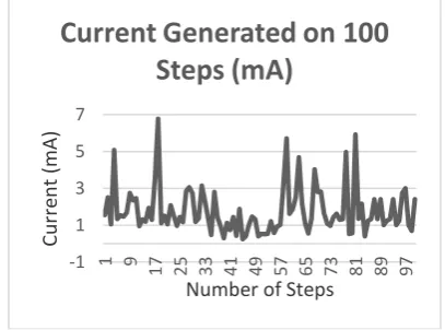
Graphical representation of current generated by floorboards (100 steps)
While doing the charging test, samples of currents generated by the board were also recorded. In these data, the value of the average current was 1.78mA from 100 steps. The highest recorded current was 6.77mA because of multiple people stepping on the floor boards at the same time while the lowest was 0.3mA because of the light step of the person on the floor board.
Table 3: Discharging Test
In the discharging test, there were four sets of testing. Four different loads were used to test the consumption of the battery charge for three hours based on the intended load. The 3W load reduced the battery voltage by 0.04 volts while the 5W load reduced the battery voltage for 0.7 volts. The combined 5W and 3W load reduced the battery voltage for 0.11 volts while the combined two 5W load reduced the battery voltage for 0.14 volts for the first trial and 0.12V for the second trial.
Conclusion
1. The existing design can charge the intended load, yet the project at times would not work due to mechanical stress and corrosion which lead to lower output production or even an unexpected maintenance. Making the energy harvester portable and moving it depending on the number of people passing on a certain area and having a larger stepper would force people to step on it, and thus produce greater output. The aesthetics of the energy harvester were improved by making it broader and reducing the displacement of the board when stepped on. The construction of the prototype was not mechanically-based, thus avoiding unaccounted mishaps.
2. The standards of the regulatory boards as the PEC, NEMA, and IEEE are the guides which ensured the development of the prototype is safe and functional. 3. The layout of the project made feasible the operation
of the system. Some considerations are necessary such as reduction of its height, optimization of space, portability and maintenance of rubber mats and floor mats, and resoldering of connections of the sensors 4. On the financial aspects, return of investment in this
project may take longer but it can bring in more revenue per year.
5. The design of the project meets the required output after construction with set-up of every component properly followed with minor revisions.
6. The amount of electricity produced by the floor boards is based on the pressure exerted on the sensors, the force exerted is directly proportional to the output. The heavier the weight of the people stepping on the board, the greater its output will be.
-1 1 3 5 7
1 9 17 25 33 41 49 57 65 73 81 89 97
Curr
en
t
(m
A)
Number of Steps
The more people stepping on the board would charge
the battery quicker. The sensitivity test shows the floor boards can generate 12.69V-20.03V and 1.08mA to 1.85mA on a board on a normal step with people weighing 40-80kg. The floorboards can withstand impact of two jumping persons with the weight of 70 kg each. For the charging test, the floor boards can generate a range of 0.03V- 0.14 V; for the discharging test, there were four sets of testing. Four different loads were used to test the consumption of the battery charge for three hours based on the intended load. The 3W load reduced the battery voltage by 0.04 volts while the 5W load reduced the battery voltage for 0.7 volts. The combined 5W and 3W load reduced the battery voltage for 0.11 volts while the combined two 5W load reduced the battery voltage for 0.12V to 0.14 volts.
7. The project promotes sustainability in preserving the environment for it is clean and free energy. As desired, it will help in illuminating the entrance of the CEAFA building and the university in reducing its electrical bill on two LED lights. The project has a deep potential if given more time of study which will prove useful to society and the economy when applied to a larger scale.
Recommendation
To maximize use and generation of energy for the piezoelectric floor board, the researchers recommend the following, which may be worked on by the next set of researchers:
1. Addition of more piezoelectric sensors connected in parallel to have higher output current from the boards for it to charge faster.
2. Use of lighter material for the board’s casing for it to be more portable.
3. Fit the boards on the location with more people to maximize the power generation.
4. Reduce height of the board so that it can match the step height of the stairs where it is installed.
5. Cover a larger area so that multiple steps can be attained for each person.
References
[1]. Philippine Electrical Code Part 1 Volume 1 (2009)
[2]. National Electrical Manufacturer Association
[3]. Spotlight on Photovoltaics& Fuel Cells: A Web-based Study & Comparison" (PDF). (2007).
[4]. Sta. Maria, Hipolito,(2001) Engineering Economy 3rd edition
[5]. Andosca et al, (2012), The Experimental and Theoretical Studies on MEMS Piezoelectric Vibrational Energy Harvesters with Mass Loading.
[6]. Bustamante et al., (2011). Generate Energy Using Piezoelectric Crystals
[7]. Dayou et al., (2009) The Use of Piezoelectric Material to Generate Electricity.
[8]. Tsz-Ho NgandWei-Hsin Liao. (2004)The Study
of a Self-powered Piezoelectric Sensor
[9]. Worthington et al., (2010). A Design Study on the Geometric Parameters of Cantilever-based Piezoelectric Energy-harvesting Devices (EHD)
[10].Aluminum Nitride, retrieved from www.surmet.com/technology/aln/
[11].Ammeter, retrieved fromhyperphysics.phy-astr.gsu.edu/hbase/magnetic/movcoil.html#c3
[12].Barium Titanate, retrieved from www.americanelements.com/ batioxnp.html
[13].Connecting Wiresretrieved from www.almansourtrading.com
[14].Energy source, retrieved from www.energysource.us.com
[15].Gallium Orthophosphate, retrieved from www.rodit.com/SingleCrystal.html
[16].Multimeter, retrieved from
mechatronics.mech.northwestern.edu/design _ref/tools/
[17].My Sunlight Solar Systems Pvt Ltd., 2012, http://www.mysunlight.co.in/Solar_Charge_Cont roller.php
[18].Piezoelectric Effect, retrieved from
www.nanomotion.com/piezo-ceramic-motor-technology/piezoelectric-effect/
[19].Piezoelectricity, retrieved from http:/whatis.techtarget.com/definition/piezo
electricity
[20].PolyvinylideneFluoride,retrieved
fromwww.porex.com/technologies/materials/
[21].Power generation, retrieved from www.kids.esdb.bg/elproduction.html
[22].Quartz,retrieved from
minerals.net/mineral/quartz.aspx
[23].Tim Stilson, 1996 Piezoelectric Sensors, http://soumdlab.cs.princeton.edu/learning/tutorial s/sensors/node7.htm
[24].V. Ryan, 2002-2009, Diodes, retrieved from http://www.technologystudent.com/elec1/diode1. htm