Integrated Starter Alternator using PMSM
Pranoti Gathadi#1, A.A.Bhole *2
Department of Electrical Engineering, Government College of engineering Aurangabad
Maharashtra, India
Abstract
The development of hybrid electric vehicle (HEV) is gaining much popularity in recent years as to fulfil the aim of reduction in oil import bill. This paper describes a system which acts in both motoring as well as in generating mode by selecting proper choice of motor and control circuitry. Permanent magnet synchronous motor (PMSM) proves to be a good choice among the entire AC machine due to its flux weakening capability. The paper describes the control strategy with discrete PI controller so as to control the Integrated Starter Alternator (ISA) in both starter as well as generating mode by sensing the internal combustion engine (ICE) speed. Field oriented control helps to control speed and torque of the system. A 48V/12V ISA system is developed so as to increase fuel efficiency of hybrid electric vehicle.
Keywords - -Integrated Starter Alternator,
Permanent magnet synchronous motor,Discrete PI controller with external anti-windup,Field oriented controller(FOC),Space vector PWM, DC-DC buck converter.
I. INTRODUCTION
Nowadays,technology is more focused on electric and hybrid electric vehicle which ensures reduction in consumption of fuel and emission of harmful gases.HEV at present proves to be a vital option till more prominent pure electric vehicle is developed.In a conventional automotive system electric machine and drives used in vehicle were not capable of providing high starting torque hence a separate starter and alternator was used which increased the weight and also additional space was occupied.With the development in power electronics and drives a single machine is able to operate as a starter and alternator,such a system is known as ISA.Depending on the requirement of the ICE, ISA operates as a motor or alternator[1].
The control strategy plays an important role in proper functioning of ISA so as to have more efficient operation of hybrid electric vehicle.This paper describes a PMSM based ISA. Different types of AC machines prove to be suitable candidates for ISA system. But among all the AC machines Permanent magnet synchronous motor (PMSM) is gaining more popularity due to its high starting torque, low maintenance cost, and good flux weakening operating region. PMSM operates in constant torque mode when its speed is less than base speed and operates in
constant power mode when speed is above the base speed. This characteristic of machine helps in cost reduction of the system [2].The control strategy plays an important role in proper functioning of ISA so as to have more efficient hybrid electric vehicle.
This paper describes a parallel hybrid electric vehicle of PMSM based ISA scheme for 48V and 12V power net. The proposed control scheme used is based on field oriented control (FOC) which helps in suitable torque and speed control of ISA. The pulse signal for the switches is generated using pulse width modulation (PWM) technique.
II. OVERVIEWOFISA
ISA basically performs the function of starter and alternator (generator). The proposed system uses PMSM which functions as motor and alternator depending on the speed of the ICE. Motor as shown in the Fig. 1 is attached to the shaft of ICE and also to the battery with the help of the converter, which takes care that battery is charged up to 48V.An IC engine is connected to ISA, a 48V battery is used to power the 48V loads placed in hybrid electric vehicle and also to supply power to ISA when it’s operating in motoring mode.
This 48V system with the help of buck converter charges the 12V battery which is used to power low voltage loads in HEV. The PMSM performs as motor when the speed of the IC engine is below the prescribed minimum cranking speed [3]. Below this speed an IC engine would be in off condition and battery would supply power to engine so as to achieve a minimum torque. The power electronic converter present helps to convert AC to DC and vice versa with the help of bidirectional converter. Controller is used so as to operate ISA in generator as-well as motoring mode by sensing the IC engine speed. The control technique used for controlling of the system is Field oriented control to control the speed and torque of the motor with the help of stator current.
A. Basic Function of ISA
The basic functions of an ISA system are: 1.Automatic start and stop for fuel conservation. 2.Provides high efficiency compared to traditional
system.
3.Act as bi-directional power converter. 4.Noise free and efficient operation of ICE To Control vehicle speed we need to use accelerator or brake pedal, as per the operation mode required by the IC engine the applied torque must be either positive or negative. A vehicle is pushed forward by the tractive force produced by the vehicle torque and transferred to vehicle wheels by the transmission unit. Speed of the engine is defined as gear ratio between the crankshaft and the vehicles wheel and transmission line. Engine torque depends on speed and acceleration required, and the torque required is the summation of generated torque by ISA and IC engine expressed in equation (1)
(1) The torque generated by ISA and IC engine varies but the total amount of power required being generated should remain same. When braking is demanded by the driver, total power can be expressed by equation (2)
(2) In equation (2) very small amount of torque is required by IC engine. Majority of torque is absorbed by ISA and if some amount of torque remains, then friction brake handles the torque [4].
B. ISA Modelling (PMSM)
Permanent magnet synchronous motor is used for ISA in dq model with rotor fixed reference frame can be described by equation (3)-(6)
The voltage equation for rotor fixed reference frame are given as in equation (3)-(4)
(3)
(4) The electromagnetic torque is given by equation (5)
(5)
The generalized motor equation is given by equation (6)
(6) The electromechanical power is given by equation
(7)
(7)
Where,
– d and q axis voltage - d and q axis flux linkage - d and q axis current - Mechanical rotor speed
- Electrical rotor speed P – Number of pole pair [5].
III.PROPOSEDCONTROLTECHNIQUESOF
ISAFORHEV
For EV and HEV drives, precise speed control and speed torque characteristic is an important parameter. Various torque and speed control techniques are adopted, but for control of any motor such as for PMSM, rotor position detection is an essential parameter to be considered, so as to have a proper synchronization between flux and current vector. Conventionally, rotor position detection method involves use of different hall sensors and coils. Field oriented control system proves to be a good choice for controlling of ISA in motoring and alternating mode [7].
A. Field Oriented Control(FOC)
This method describes control of torque and speed which is directly proportional to electromagnetic state of motor same as in case of DC motor. This method is very useful for application where wide speed range i.e. from zero to maximum speed is required and where full torque is needed to be produced even at the zero speed operation [8]. In this method there are two constants as an input references: the flux component (aligned with d co-ordinate) and the torque component (aligned with the q co-ordinate). This method is based on controlling of stator current by transforming three phase time and speed dependent system into two Co-ordinate dq systems by using
equation (10).
=
(10)
As in case of PMSM, d axis current is kept zero as the rotor flux is fixed and determined by magnets. The Fig. 2 shows the proposed control system for field oriented control. In the control scheme torque controller is used in order to select torque reference which is given as an input to current reference generator.
This is used to limit the generated torque within a permisible range.Current controller is employed with park transformation which is controlled by discrete PI controller.Pulse width modulation(PWM) three phase, two- level generator generates the required signal which is further given to Power converter connected to PMSM[6].
B. Space Vector Pulse Width Modulation(SVPWM)
This is one of the best techniques of PWM as it helps in reducing total harmonic distortion. For three phases, two level PWM inverter used is described as three phase quantities as vectors in two dimensional planes. The space voltage vectors are considered as reference voltage and output voltages are space vectors. There are total eight switches present out of which two are zero switches (V1, V8) and six are active switches (V2-V7) [7].
Fig. 3 Space Vector PWM [7]
C. Discrete PI Controller
The proposed system uses a unique type of PI controller which has discrete inputs and also anti rest windings; this type of controller is used for a nonlinear type load. For an integral term saturation point at upper and lower level is considered. Anti-reset windup will not accumulate if the controller output is saturated at an upper or lower limit. The system provides more accuracy in case of HEV and also helps in reducing error.
D. DC-DC Buck Converter
DC to DC buck converter used has the characteristic of stepping down the voltages. The system consists of power devices and passive components. The conversion of high side input voltage to low side output voltage is done by equation (11).
(11)
A controller consists of switching device which helps in controlling the voltages of buck converter which converts 48V dc into 12V dc by using the buck converter. The value of capacitor is kept large enough so as to reduce ripple current and a diode is used so as to support flow of voltage in both directions. The Fig. 4 shows the MATLAB simulation model of buck converter used in the system [8].
Fig. 4 MATLAB simulation model of buck converter
IV. MATLABSIMULATIONRESULT
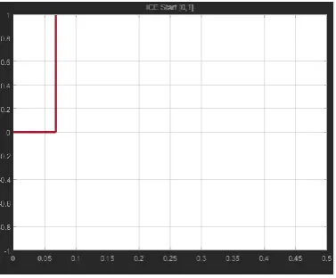
In this system interior permanent magnet synchronous motor is used which operates in both motoring and alternating mode. When the speed of the ICE is below the prescribed minimum speed of 700 rpm PMSM operates in motoring mode and when the speed goes above 700 rpm electrical machine controller senses the speed and ISA operates in alternating mode
.
Fig. 5 MATLAB Model
TABLE I.PARAMETERS OF ISA FOR HEV
Parameters Unit Values
Maximum Power Pm 14KW
Maximum Torque Tm 50Nm
Stator d axis inductance Ld 0.1mH
Stator q axis inductance Lq 0.3mH
Stator zero axis inductance
L0 0.05mH
Stator Resistance Rs 0.005 mohm
Permanent magnet flux linkage
ψ 0.04Wb
No. of pole pair P 2
A. Motoring Mode
positive in this mode; maximum torque supplied is 50Nm as shown in Fig. 5(c). During starting condition when ICE has not reached its minimum speed, the dc voltage drops because current is flowing out of the battery i.e. voltage is less than 48V as shown in Fig. 5 (d)
(a) IC engine in Off Condition
(b) Q axis current
(c) Torque when IC engine is Off
(d) Battery Voltage when IC engine is off Fig.5 MATLAB simulation result when IC engine is
below prescribed speed.
B. Alternator Mode
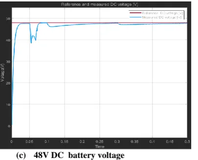
This mode of operation occurs when ISA reaches above the speed of 700 rpm which is the minimum required speed for engine to start. Fig. 6(a) shows the graph when IC engine is turned ON. When ICE turns on ISA operates in alternating mode. The q axis current component is a negative in this mode as shown in Fig. 6(b). Torque supplied is negative as in generating mode torque is negative as shown in Fig.6 (c). In this mode the battery is charged by supplying power to 48V battery from the alternator as shown in Fig. 6 (d). In this mode battery voltage rises to 48V.
(a) IC Engine is On Condition
(a) Q axis current
(c) 48V DC battery voltage
Fig. 6 MATLAB Simulation Result when IC engine is
on condition
V. CONCLUSIONS
This paper describes an ISA and its control topology for HEV application. In this field oriented control is used so as to control PMSM in both motoring as well as alternating mode depending on the speed of IC engine.
REFERENCES
[1] L.A Viorel, Lorand Szabo, Cristian Stet, Lars Lowenstein, “Integrated Starter-Generator for Automotive Applications”, Research gate, Vol.45, No.3, May 2004, pp. 256-260.
[2] Chunhua Liu,, K. T. Chau, J. Z. Jiang, “A Permanent-Magnet Hybrid Brushless Integrated Starter–Generator for Hybrid Electric Vehicles”, IEEE TRANSACTIONS ON INDUSTRIAL ELECTRONICS, Vol. 57, No. 12, Dec. 2010, pp. 4055-4064.
[3] Taehyung Kim, Sangshin Kwak, “A Flexible Voltage Bus Converter for the 48/12 Volt Dual Supply System in Electrified Vehicles”, IEEE TRANSACTIONS ON VEHICULAR APPLICATIONS, Vol. 66, No.3, March 2017 ,pp.2010-2018
[4] Andreas Malikopoulos, Zoran Filipi and Dennis Assanis, “Simulation of an Integrated Starter Alternator (ISA) System for the HMMWV”, Automative Research Center, The University of Michigan, April 2006, pp. 1-11
[5] Gheorghe-Daniel Andreescu, Cristina-Elena Coman, “Integrated Starter-Alternator Control System for Automotive”, IEEE International Symposium on Computational Intelligence and Informatics, Vol. 57, No. 3, 14-21 Nov 2013, pp. 339-343.
[6] G. Sree Lakshmi Dr. S. Kamakshaiah Dr. Tulasi Ram Das , “Closed Loop PI Control of PMSM for Hybrid Electric Vehicle using Three Level Diode Clamped Inverter for Optimal Efficiency”, International Conference on Energy Efficient Technologies for Sustaniablity,2013, pp. 754-759. [7] M. B. B. Sharifian. T. Herizchi , K. G. Firouzjah, “Field
Oriented Control of Permanent Magnet Synchronous Motor Using Predictive Space Vector Modulation”, IEEE Symposium on Industrial Electronics and Applications (ISIEA 2009), October 4-6, 2009,vol. 7, pp.574-579. [8] Tasi-Fu Wu, Yu-Kai Chen, “Modeling PWM DC/DC
![Fig 2: Field oriented Control [6]](https://thumb-us.123doks.com/thumbv2/123dok_us/8592721.1721582/2.595.311.520.652.753/fig-field-oriented-control.webp)