Beyond Watson and Crick:
P
rogramming the
S
elf
-
Assembly and R
econfiguration of DNA
N
anostructures
B
ased on
S
tacking
I
nteractions
Thesis by
Sungwook Woo
In Partial Fulfillment of the Requirements for the Degree of
Doctor of Philosophy
CALIFORNIA INSTITUTE OF TECHNOLOGY Pasadena, California
2013
ii
2013
iii
Acknowledgements
I was extremely fortunate and privileged throughout my graduate years. Foremost, I became the first student, and for a significant time remained the only student, of my advisor Paul Rothemund. He was an exceptional mentor and a great friend. We had a lot of fun together— making a stop-motion movie of DNA origami on a sunny Californian beach, creating a trillion ROSENs together, swimming and snorkeling in a beautiful lake in New Hampshire, and dealing with my lawsuit (I can say it was fun now that it is over). But my best memories are of our scientific discussions, which were often 6-7 straight hours spent arguing about things, developing new ideas, and, when writing together, competing to see who was the real perfectionist. I will miss those intellectually challenging moments the most. My deepest gratitude goes to Paul for his excellent guidance, patience, stimulation, and encouragement.
I was also very lucky to be part of the greater Winfree lab. I am very grateful to Erik Winfree for all his guidance and encouragement since we first met and chatted in Seoul back in 2006 (and even before our Seoul meeting through emails). Being within a group co-led by the two geniuses was a one-of-a-kind experience. I learned rigor, persistence, and ways to approach difficult problems from them. Many thanks also go to the rest of the group—Lulu Qian, Damien Woods, Ashwin Gopinath, Dave Doty, Jongmin Kim, Niranjan Srinivas, Constantine Evans, as well as visiting members Cody Geary, Denis Selnihin, Pierre-Etienne Meunier, Craig Martin, Anu Thubagere and past members, Rizal Hariadi, Nadine Dabby, Si-ping Han, Elisa Franco, Dave Zhang, David Soloveichik, Joseph Schaeffer, Hareem Maune, Ho-Lin Chen, Rebecca Schulman, Georg Seelig, Bernie Yurke, Peng Yin, Kevin Young, Seung Woo Shin, Matt Cook, Mikhail Hanewich-Hollatz, and Jerzy Szablowski—for their friendship, constructive scientific comments, and for keeping the lab a stimulating and fun place. I also thank Lucinda Acosta and Karolyn Knoll for always being helpful with ordering supplies and for being good friends.
I was very fortunate to have Niles Pierce as a committee member—he always asked critical and thought-provoking questions. Niles was also a very supportive and helpful option chair, and an exceptional teacher. I am also grateful to David Tirrell for being on my committee (we went through an earthquake together in the middle of my qualifying exam!) and for his interesting and inspiring questions. Near the end of my graduate years, I was very lucky to have interacted with two great scientists—Deborah Fygenson and Ebbe Andersen—who were visiting scholars in the lab at the same time. I thank them for carefully reading my thesis and giving me insightful comments.
iv
Sternberg, Nakul Reddy, Niema Pahlevan, Indira Wu, and Geoffrey Lovely—for their friendship and help during all the hard times we experienced working on problem sets and studying for quals together. I also thank Linda Scott for her help with many administrative tasks during my years in graduate school.
I also thank my friends in the Korean community at Caltech—Seokmin Jeon, Junho Suh, Hansuek Lee, Sinchul Yeom, Young Shik Shin, Hee-Joong Chung, Min Seok Jang, Kiyoul Yang, Dong-Wook Kim, Myoung-Gyun Suh, Taesik Oh, Daejung Kwon, Young Hyun Kim, Juyoung Kim, Haekong Kim, Ji Hun Kim, In Ho Cho, Sanghee Park, Wonhee Lee, Jina Choi, Chang Ho Sohn, Dongwan Kim, Hugh Kim, Sang-Mok Lee, Daegyoum Kim—just to name a few—who were great mentors, brothers (and a sister), and life companions.
I am grateful to Chris Rivera for his help on my project with proteins. I also thank Ethan Garner and Jessica Polka, for sharing their expertise and adding the final pinch of spices that were necessary to the soup of my experiments.
I thank Jack and Robyn Lutz, Sergii Romanenko, Michelle Bobrow, and Dave Doty (again), for joining my class “DNA nanotechnology for biologists”, putting up with my insufficient teaching skills and actively participating in discussions.
I thank Caltech and the Benjamin M. Rosen Family Foundation for generous scholarships which funded my graduate study.
From my life before Caltech, I owe a great debt to Professors Joon Won Park and Hee Cheul Choi in Pohang—for their guidance and encouragement, and for teaching me the joy of research. I also thank my parents, Hansub Woo, and Hyeongseon Cho, and my parents-in-law, Jongki Lee and Sounok Lee for their endless support and trust.
v
Abstract
Life is the result of the execution of molecular programs: like how an embryo is fated to become a human or a whale, or how a person’s appearance is inherited from their parents, many biological phenomena are governed by genetic programs written in DNA molecules. At the core of such programs is the highly reliable base pairing interaction between nucleic acids. DNA nanotechnology exploits the programming power of DNA to build artificial nanostructures, molecular computers, and nanomachines. In particular, DNA origami—which is a simple yet versatile technique that allows one to create various nanoscale shapes and patterns—is at the heart of the technology. In this thesis, I describe the development of programmable self-assembly and reconfiguration of DNA origami nanostructures based on a unique strategy: rather than relying on Watson-Crick base pairing, we developed programmable bonds via the geometric arrangement of stacking interactions, which we termed stacking bonds. We further demonstrated that such bonds can be dynamically reconfigurable.
The first part of this thesis describes the design and implementation of stacking bonds. Our work addresses the fundamental question of whether one can create diverse bond types out of a single kind of attractive interaction—a question first posed implicitly by Francis Crick while seeking a deeper understanding of the origin of life and primitive genetic code. For the creation of multiple specific bonds, we used two different approaches: binary coding and shape coding of geometric arrangement of stacking interaction units, which are called blunt ends. To construct a bond space for each approach, we performed a systematic search using a computer algorithm. We used orthogonal bonds to experimentally implement the connection of five distinct DNA origami nanostructures. We also programmed the bonds to control cis/trans configuration between asymmetric nanostructures.
The second part of this thesis describes the large-scale self-assembly of DNA origami into two-dimensional checkerboard-pattern crystals via surface diffusion. We developed a protocol where the diffusion of DNA origami occurs on a substrate and is dynamically controlled by changing the cationic condition of the system. We used stacking interactions to mediate connections between the origami, because of their potential for reconfiguring during the assembly process. Assembling DNA nanostructures directly on substrate surfaces can benefit nano/microfabrication processes by eliminating a pattern transfer step. At the same time, the use of DNA origami allows high complexity and unique addressability with six-nanometer resolution within each structural unit.
vi
Table of Contents
Acknowledgements ... iii
Abstract ... v
Table of Contents ... vi
I.
Introduction ... 1
I.1.
DNA Nanotechnology ... 1
I.2.
Towards the Development of Nanomachine Connectors ... 3
I.3.
Survey of Studies on Base Stacking ... 5
I.4.
Thesis Outline and Contributions ... 7
II.
Design and Implementation of Stacking Bonds ... 10
II.1.
Introduction ... 10
II.2.
Design, Results and Discussion ... 12
II.2.1.
Stacking of origami rectangles ... 12
II.2.1.1.
DNA sequence at blunt ends ... 12
II.2.1.2.
Global twist ... 13
II.2.1.3.
Crossover geometry at blunt ends ... 14
II.2.2.
Two approaches towards specific stacking bonds ... 19
II.2.2.1.
Binary codes ... 19
II.2.2.2.
Shape coding ... 30
II.2.2.3.
Summary and comparison of the two approaches ... 38
II.2.3.
Programming of cis-trans isomeric structures ... 41
II.2.4.
Thermodynamic measurements ... 43
II.2.4.1.
Measurement of the free energy of stacking bonds ... 43
II.2.4.2.
First energy model: assuming loop-loop interactions are neutral ... 44
II.2.4.3.
Second energy model: fitting with non-zero loop-loop interactions ... 47
II.3.
Conclusion and Future Directions ... 49
II.4.
Materials and Methods ... 52
II.4.1.
General ... 52
II.4.2.
Design of origami ... 52
II.4.3.
Preparation of origami ... 53
II.4.4.
Atomic force microscopy (AFM) ... 54
II.4.5.
Detail aspects in the design process ... 54
II.4.5.1.
Searching for large orthogonal sets of sequences ... 54
II.4.5.2.
Warnings: potential technical issues in designing DNA origami ... 56
II.4.6.
Supplementary materials ... 60
III.
Two-Dimensional Crystallization of DNA Origami Checkerboards via
Cation-Controlled Surface Diffusion ... 62
III.1.
Introduction ... 62
III.2.
Results and Discussion ... 65
vii
III.2.2.
Factors that allow two-dimensional assembly ... 66
III.2.3.
Why checkerboards, not linear chains? ... 68
III.2.4.
Effects of the strength of stacking interaction ... 70
III.2.5.
Effects of the concentration of divalent cation ... 72
III.2.6.
Crystal size is limited by irregularity of mica ... 74
III.3.
Conclusion and Future Directions ... 76
III.4.
Materials and Methods ... 77
III.4.1.
Surface diffusion assembly ... 77
III.4.2.
Atomic force microscopy (AFM) ... 77
IV.
ParMRC and Expandable DNA Nanostructures ... 78
IV.1.
Introduction ... 78
IV.1.1.
Using DNA origami to study biophysical questions ... 79
IV.1.1.1.
The ParMRC system ... 79
IV.1.1.2.
Open questions ... 81
IV.1.1.3.
DNA origami design: proposed and actual ... 83
IV.1.2.
Building expandable structures using growing biopolymers ... 86
IV.2.
Results and Discussion ... 88
IV.2.1.
Biophysical studies of the ParMRC system ... 88
IV.2.1.1.
AFM studies of ParR binding to
parC
on origami ... 88
IV.2.1.2.
Origami with multiple
parC
strands ... 95
IV.2.2.
Expandable nanostructures ... 101
IV.2.2.1.
Model system: origami as ParR/
parC
cores stabilizing ParM filaments 101
IV.2.2.2.
Expanding origami chains ... 108
IV.2.2.3.
Control system: non-expanding DNA nanotubes ... 118
IV.3.
Conclusion and Future Directions ... 121
IV.3.1.
Expandable triangles ... 122
IV.3.2.
Effects of distance between ParR/
parC
complexes on ParM filament
connection ... 123
IV.3.3.
Effects of the number of
parC
sites on single origami structures on the
growth rate of ParM filament bundles ... 124
IV.3.4.
Cup experiments ... 124
IV.3.4.1.
Is it just the geometry that really matters? ... 124
IV.3.4.2.
Would the active site in ParR alone stabilize filaments? ... 125
IV.4.
Materials and Methods ... 125
IV.4.1.
Preparation of DNA origami ... 125
IV.4.1.1.
DNA origami with a single
parC
... 125
IV.4.1.2.
DNA origami with multiple
parC
strands ... 126
IV.4.2.
Preparation of microbeads with
parC
... 127
IV.4.3.
Preparation of proteins ... 128
IV.4.4.
Preparation of ParM polymerization buffer ... 128
IV.4.5.
AFM of
parC
-origami, ParR, and ParM ... 129
IV.4.6.
Gel electrophoresis of
parC
-origami with ParR ... 129
IV.4.7.
Preparation of glass slides ... 129
IV.4.8.
Sample preparation for fluorescence microscopy ... 130
1
C h a p t e r I
Introduction
“Once we accept our limits, we go beyond them.” - Albert Einstein
I.1.
DNA
N
anotechnology
Many critical phenomena in biology are governed by the operation of molecular programs, written in the form of genetic code in DNA molecules. The programs are executed by a set of basic rules known as the central dogma: information in DNA is transcribed to RNA (by RNA polymerase), which is in turn translated into proteins (by ribosome), and then proteins perform complex tasks and determine phenotypes of the organism. There are complicated and exquisite machineries involved in each of these processes, but the software, the program itself is all – with the exception of RNA viruses, so far as is known to humans to date – in the molecule DNA.
DNA nanotechnology is a field that takes a direct shortcut from DNA to interesting and useful structures and functions without the help of protein machineries. We use the programming power of DNA to design and implement complex tasks almost purely out of DNA. We often borrow ideas from nature and try to mimic what nature does – from folding1, to neural networks2, to molecular walkers3-7 – and we often go beyond, e.g., a smiley face1 of ~100 nm scale does not exist
in nature and no living organism with 4 neurons can play ‘read your mind’ games with a human2. DNA nanotechnology is in that sense a branch of synthetic biology, which aims to fabricate biological systems that do not exist in nature.
2
thermodynamic equilibrium a collection of DNA molecules forms the desired structure. The focus of research has been on how one transforms information between the two domains: structure and sequence. The birth of the field originates from a very simple idea, in retrospect, that instead of two DNA strands with complementary sequences coming together and just forming a linear duplex as usual, one could design the sequences of four DNA strands such that a half of each strand has complementarity to only a half of another strand, so that they altogether form a crossbar-like immobile four-way junction8,9. By extending the ends of each duplex with short single-stranded
domains8, termed ‘sticky ends’, and by introducing extended versions of the four-way junctions10, usually referred to as tiles, for rigidity and functionality, researchers have created lattices11 with
periodic patterns and implemented computation by structures formed by algorithmic self-assembly12-14. Then the breakthrough invention of DNA origami1 changed the paradigm for methods of transformation between structure and sequence. It introduced the concept of folding: it uses a long single-stranded DNA as a scaffold and folds it into a desired shape with the help of many short strands, thereby enabling the creation of arbitrary (within limits) shapes and patterns at the ~100 nanometer scale. The technique, which was originally developed for two-dimensional shapes, was soon extended to enable the folding of complex three-dimensional shapes15-17. More
recent advances in structural DNA nanotechnology include the development of a two dimensional molecular canvas18 and three dimensional DNA bricks19, which significantly improved modularity20 in creating shapes by using uniquely addressed single-stranded tiles.
The development and use of DNA nanostructures as structural templates for further functionalization and manipulation of other components can be largely considered within the boundary of structural DNA nanotechnology. For example, DNA origami was used to program the alignment of carbon nanotubes for the bottom-up construction of a nanoscale transistor21, to create a
molecular analog of DNA chips that detect specific RNA targets22, and to monitor chemical reactions with single-molecule resolution23. DNA nanostructures have also been used as
custom-designed tools for studying biological systems, e.g., as a structural template to study the effect of the distance of binding sites on multivalent ligand-protein binding24, as picture frame shaped
architecture for direct observation and regulation of DNA-protein interactions25,26, and as a molecular rope for studying tug-of-war behavior between motor proteins27.
3
metastable state and another. By exquisitely programming the conditional changes of the states of the molecules (and the rates of those changes), researchers have developed digital logic circuits28,29, DNA tweezers30, and molecular walkers3-7. One of the most widely used mechanisms for such
programming is toehold-mediated strand displacement31. It is the mechanism by which a free strand
of DNA and a partially-complementary duplex containing a small single-stranded region (“toehold”) can rearrange to form a duplex with greater complementarity, often displacing one of the two originally duplexed strands, without complete dissociation of the initial duplex via a random walk process called branch migration. Such reactions occur isothermally at rates somewhat well understood32. By embedding (often sequestering) toeholds and their complements in multiple
molecular species, multi-level downstream reactions can be programmed to execute sequentially. Naturally, there have been attempts to combine these two aspects of DNA nanotechnology and create nanostructures that conditionally change their configuration in response to input of other DNA strands. Yan et al. developed a tile-based nanodevice that switches between two states and rotates the structure attached to it by removal and addition of external strands33. Andersen et al.
created a three-dimensional box that opens its lid upon input of key strands15. Han et al. devised a structure that can be partially cut by input of a set of strands and changes its configuration34.
Douglas et al. developed a clamshell-like container that can hold molecular payloads inside the container and opens conditionally by the binding of specific antigens from cells to release the payloads35.
I.2.
Towards the
D
evelopment of N
anomachine
C
onnectors
Although there have been developments of dynamic nanostructures by combining structural and dynamic aspects of DNA nanotechnology, the level of complexity and exquisiteness is far from what nature has. For example, the bacterial flagellum that allows some bacteria, e.g., E. coli, to swim around the environment is driven at its base by a reversible rotary motor36 (Figure I-1a). The
motor is about 45 nm in diameter and is assembled from about 20 different kinds of parts. Some parts are embedded stationary in the cell membrane, while allowing other parts to freely rotate against them.
4
assembly but are easily breakable by forces from neighboring components. We would also need some connectors that first initiate the assembly, then conditionally rotate by some mechanical interactions while maintaining the contact with the next components (see Figure I-1b). Chemically synthesized mechanically interlocked molecular architectures, such as rotaxanes and catenanes, have been used to create molecular shuttles or rotary motors that operate by chemical or photochemical stimuli37. However, for structural control and programmability of individual components over wide range of length scales, DNA is the most convenient and promising medium for designing nanomachines.
Figure I-1. The rotary motor of bacterial flagella and stacking-bond-based rotation parts. (a) An electron microscope (EM) image of the rotary part of a bacterial flagellum adopted from ref. 36. (b) A conceptual drawing of rotating machine parts using stacking bonds as the connector. Stacking bonds may be used as connectors that first guide specific self-assembly between parts, and then allow rotation by sliding past each other while maintaining contact, under external shear forces.
In this thesis we describe the development of specific and programmable bonds between DNA nanostructures based solely on stacking interactions, as potential connectors that are easily reconfigurable by forces. We achieve programmability by geometric alignment of the stacking interaction units, blunt ends—the termini of a DNA duplex. We believe that such bonds, termed
stacking bonds, can achieve those functions described above. Stacking bonds only involve face-to-face attraction of blunt ends, unlike bonds based on base-pairing interactions that would require structural interdigitation of the connecting strands. We believe that stacking bonds would require much smaller forces to break than base-pairing bonds with similar energy, especially when the force is applied in the shear direction, because the potential stepwise breakage would require much smaller force for each step than the case of breaking the base pairs all at once after elastic extension.
22
BERG
Annu. Rev. Biochem. 2003.72:19-54. Downloaded from www.annualreviews.org by California Institute of Technology on 06/02/11. For personal use only.
Stationary
part
Rotating
part
5
Figure I-2 shows schematic force-distance curves adapted from the literature for the cases of pulling a DNA duplex in the axial direction38 (Figure I-2a) and of “unzipping” a DNA duplex39 (Figure I-2b). While a DNA duplex undergoes elastic extension and abrupt rupture when pulled in the axial direction, when unzipped, a DNA duplex exhibits a sawtooth-like curve involving stepwise breakage of base pairs with smaller force for each step. We hypothesize that the breakage of stacking bonds under shear force would exhibit a similar behavior to the case of unzipping a DNA duplex.
Figure I-2. Schematic force-distance curves, for the case of (a) a DNA duplex when pulled in the axial direction (adapted from ref. 38), and for the cases of (b) a DNA duplex when “unzipped” (adapted from ref. 39) and a pair of DNA origami nanostructures connected by stacking bonds when pulled in the shear direction (hypothetical). The direction of applied force is represented by arrows in each case.
With a similar mechanism of stepwise rearrangement requiring small force for each step, stacking bonds may serve as connectors that allow rotation while maintaining the contact—the kind of challenge described above, as inspired by nature’s nanomachine bacterial flagellum. The alignment of blunt ends on the same surface and the face-to-face configuration of stacking bonds would give a ‘smooth’ bond surface and would allow sliding of the bonded surfaces against each other.
This thesis represents a primitive step towards the development of such connectors for molecular machines. We present the design and implementation of stacking bonds as programmable and chemically stable bonds. We further demonstrate dynamic separation of stacking bonds that once connected DNA origami nanostructures by exploiting a force-generating filament protein system.
I.3.
Survey of
S
tudies on B
ase
S
tacking
While the base pairing interaction of DNA seems to be well understood, it is hard to separate
F
d
F
d
(a) (b)
6
the relative contributions of base stacking and hydrogen bonding. Theoretical and computational investigations on the chemical nature of base stacking have suggested that the interaction is mainly governed by dispersion attraction (instantaneous dipole – induced dipole interaction)40,41. But such
studies are usually performed assuming a gas phase, i.e., no molecules other than DNA, to eliminate any potential interaction from other species, especially water, and characterize the ‘intrinsic’ energies. In real systems, in which DNA is usually surrounded by water molecules and ions, the base stacking interaction would have to be considered as a combination of multiple interactions, such as the intrinsic dispersion interaction, the hydrophobic interaction (an entropic effect for water molecules), and the ion-induced dipole-dipole interaction.
Experimentally, the base stacking interaction, independent of hydrogen bonding, can be observed by examining the binding between blunt ends. Blunt-end stacking between individual duplexes is negligible at the concentrations typically used in biochemistry experiments, but at extremely high DNA concentrations (~100 mM), it causes short DNA duplexes to connect end-to-end into long chains, which align to form liquid crystals42. DNA origami enabled the observation of
blunt-end stacking at a much lower concentration (~1 nM)1, because each origami nanostructure carried multiple blunt ends in a linear arrangement along the edges that can bind cooperatively.
In the study of liquid crystals of DNA42, the energy of stacking was estimated, based on the
average lengths of chains and the concentration of DNA, to be on the order of ~ –5 to –2 kcal/mol (in distilled water, ~20 °C). A molecular dynamics simulation study based on pulling simulations estimated the energy to be ~ –6 kcal/mol (1 M DNA in 120 mM NaCl, two DNA molecules in a box)43. An experimental attempt to directly measure the free energy of the stacking interaction in a
condition more relevant to biochemical systems (Tris-Borate-EDTA buffer, pH 8.0, 37 °C) was carried out using a short duplex fragment that contained a nick (a break in the phosphate backbone) in the middle44. The free energy of stacking was estimated based on the equilibrium ratio between the bound and unbound states of the duplex at the nicked site. Each possible pair of blunt end sequences was examined and showed the free energy values between –2.17 and –0.19 kcal/mol. We also measured the stacking energy using our stacking bonds between DNA origami, and compared the value with their values, which showed a good agreement as will be discussed in Chapter II.
Certainly we were not the first ones who tried to employ stacking interactions for construction of DNA nanostructures. Wang et al. used three-helix tiles with blunt ends on each edge to create long chains and one-dimensional arrays of streptavidin45. Endo et al. created ‘jigsaw piece’
7
the help of the stacking interaction between the edges (although strictly speaking the edges did not have blunt ends: they used four-thymine loops to prevent stacking during the assembly of each pieces). Both of these studies exploited the stacking interaction merely as a source of stable connection, but did not attempt to achieve specificity or programmability.
I.4.
Thesis
O
utline and
C
ontributions
The following chapters describe our development of stacking bonds and investigation of their potential for reconfiguration. Chapter II is based on a peer-reviewed publication, and Chapters III and IV present work that is not yet published.
Chapter II describes the design and implementation of stacking bonds. We first explore the stacking phenomenon of origami rectangles and flesh out some detail aspects and improve the performance of stacking between origami. We recognize the presence of the global twist in the original 2D origami, explain its origin, and create twist-corrected rectangles to improve bond fidelity and stability. By investigating the effect of the crossover geometry at blunt ends, we discover stacking polarity and find an optimal geometry for the creation of stacking bonds. For the design of diverse bond types, we introduce two different approaches: binary coding and shape coding of geometric arrangement of blunt ends. For each approach, we set up binding rules that derive from the stacking polarity and the nature of each approach. We define a set of design constraints, such as the number of active patches and the maximum number of allowed incorrect matches. We wrote computer programs to search and construct the bond spaces for each approach, and to explore the orthogonality between bond types. We experimentally demonstrate some of the bond types from each approach and present atomic force microscope (AFM) images for both origami chains based on single bond types and chains connected via orthogonal bond types. We further present data for stacking bonds programmed to control the cis/trans configuration between origami nanostructures. We estimate the stacking bond energy based on AFM results and we provide two different models: a nonlinear energy model with respect to the number of blunt ends on origami edges, and a linear energy model under the assumption that loops that were considered inert by design might contribute to the stability.
8
develop the idea of binary coding in addition to the shape coding approach. All computer programs for the construction of bond space under various constraints for both approaches were written by me. All experiments for investigating the stacking properties between rectangle origami and for testing and characterizing the stacking bonds via binary and shape coding approaches were performed by me. Experiments with corner origami for the cis/trans configuration and the statistical analysis were performed by Paul Rothemund. All other statistical and numerical analyses for stacking bonds and the stacking energy estimation were done by me. This work was published in full as: Sungwook Woo & Paul W. K. Rothemund, “Programmable Molecular Recognition based on the Geometry of DNA nanostructures”, Nature Chemistry, 3, 620-627 (2011), doi: 10.1038/nchem.1070.
Chapter III describes large-scale self-assembly of DNA origami into two-dimensional checkerboard-pattern crystals based on a surface diffusion protocol. We describe our understanding of the surface diffusion phenomena and the protocol where the diffusion of DNA origami occurs on a mica substrate and is dynamically controlled by changing the cationic condition of the system: Mg2+ first fixes origami to a mica surface, Na+ makes them mobile while still keeping them on the surface, then Ni2+ fixes the resultant structure back onto the surface. The protocol also involves
incubation under an elevated temperature. A series of systematic experiments suggested that Na+
and the surface are the essential factors, while heat merely facilitates the process. We found that the origami rectangles prefer the checkerboard pattern to a linear form because of their global twist and provide evidence based on control experiments carried out with twist-corrected origami. We explore the effect of the strength of the stacking bonds connecting origami on the assembly pattern: stronger stacking bonds mediated by larger contact area prevented the formation of checkerboard pattern crystals, again due to global twist. We also describe the discovery that the crystal growth on mica is limited by the nonuniform charge density of mica.
This work started and proceeded as a side project of the stacking bond project described in Chapter II. The idea of testing origami containing stacking patches at four corners was initiated by me during the early stage of investigating the stacking property of rectangle origami. The idea of testing different cation conditions emerged while chatting about the system with Si-ping Han. All the experiments for understanding the behavior of origami on surface and characterizing the effect of various factors were designed and performed by me. This work has a manuscript in its draft form to be submitted soon.
9
copy of the cell’s DNA by actively pushing each copy to the opposite poles of the cell. One perspective is to use DNA origami as a custom tool to study some unknown biophysical aspects of the machinery at the single-molecule level. We present a series of AFM studies that track the binding of components of the system on top of our origami template, and compare the results quantitatively with previously reported data from ensemble experiments. The second perspective we take is to exploit the dynamic property of the ParMRC system to engineer expandable nanostructures: we break stacking bonds between DNA origami by anchoring the binding sites of the protein system on each origami. We estimate the forces relevant to breaking the bonds with the protein system, and show preliminary fluorescence microscopy data for expanded structures, along with data from control experiments using DNA nanotubes.
10
C h a p t e r I I
Design and Implementation of
Stacking Bonds
†
“So beautiful it has to be true.” - James D. Watson
II.1.
Introduction
DNA base pairing is unique among mechanisms for molecular recognition47since it allows
the creation of combinatorially diverse bonds: the number of possible binding interactions scales exponentially with polymer length so that a polymer of just N nucleotides A, T, G, or C can express
on the order of 4N binding interactions. In practice, many sequences are unusable, exhibiting
undesired interactions with themselves or other sequences. But with attention to base composition, secondary structure, sequence homology, and thermodynamics, extremely large sets of orthogonal sequences (~240,000; N=25) can be designed to bind within a narrow range of melting temperatures48.This ability to instantiate diverse binding interactions has driven the creation of a wide variety of DNA nanostructures1,3,8,11,16,49, molecular computers28,50,51, and nanomachines4,30,52.
While DNA hybridization is extremely powerful, researchers have developed numerous artificial systems for molecular and macroscopic recognition using simple interactions including hydrogen bonds53,π-π stacking54,55, entropic depletion56,57, and capillary forces58,59. There has been
little development, however, of general systems capable of creating combinatorially diverse
11
bonds; each new type of interaction typically requires unique design insights and considerable synthetic effort. Besides DNA, other information-bearing heteropolymers like proteins might be used for combinatorially diverse bonds. Yet even for well-understood systems such as protein coiled-coils60, no systematic method exists for designing multiple orthogonal bonds.
Towards understanding and recreating the recognition properties of DNA it is natural to ask, “What causes two complementary DNA strands to bind?” While the first answer that may spring to mind is the hydrogen bonding between base pairs, base stacking between adjacent base pairs is apparently the dominant stabilizing factor in DNA binding44,61,62. The dominance of stacking is consistent with the sequence-dependent strength of DNA binding because stacking is itself sequence-dependent: the strongest stacking occurs between a GC pair and a CG pair (-2.17
kcal/mol), the weakest stacking at AT/TA (-0.19 kcal/mol)44. The nearest neighbor model for the
strength of DNA binding63-65owes its success over the base-composition model (simply counting
AT and GC pairs) to the fact that it includes stacking. One consistent picture is this: stacking provides much of the binding enthalpy for the duplex, and base pairing enforces specificity.
The question arises whether stacking alone can be used to create specific molecular recognition. Pure base stacking can be studied by examining the binding between blunt ends, the termini of a DNA duplex. Blunt-end stacking between individual duplexes is directly observed only at extremely high (~100 mM) concentrations42, but DNA nanostructures such as 3-helix tiles45
and 24-helix origami1 form long chains at much lower (500 nM and 1 nM) concentrations due to cooperative binding of multiple blunt ends. In achieving specific bonds using stacking, one might expect some difficulties. First, in contrast to base pairing which involves heterophilic (“like-unlike”) attraction, blunt-end stacking involves homophilic (“like-like”) attraction. Whether combinatorially diverse bonds in homophilic polymers are even possible has been an open question since Crick first suggested that the primitive genetic code might have been homophilic66. Second, DNA uses two types of attraction (A-T and G-C), so how can
combinatorially diverse bonds be constructed from just a single type of attraction?
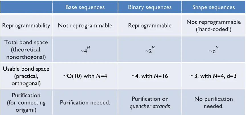
Here we present two general approaches to programming combinatorially diverse and specific bonds in a scalable fashion from a single homophilic interaction. Both approaches use DNA origami to create stacking bonds—geometric arrangements of stacked blunt ends. We map these arrangements onto abstract sequences, use computer algorithms to find sets of sequences predicted to be orthogonal, and experimentally test sets for orthogonality. The first approach encodes bond type using a 16-bit binary code along the edges of an origami rectangle. It is
12
second approach encodes bond type using geometric complementarity between pairs of “Manhattan skyline” edge shapes, with N “skyscrapers” each having one of M heights; the case of N=4 and M=3 with 34=81 bond types is explored. This approach is not reprogrammable (each origami is
“hard-coded”—a unique origami must be synthesized for each shape) but is experimentally simpler. In both systems, symmetry and mismatch constraints limit the number of bond types and size of orthogonal sets. Non-idealities like the flexibility of edges further decrease the number of usable bond types. We demonstrate the combination of origami using orthogonal sets of up to four distinct bond types. Finally, we use both systems to control the cis/trans geometry of multi-origami structures.
II.2.
Design
, Results and Discussion
II.2.1.
Stacking of origami rectangles
We first explored stacking using a rectangular origami with 24 blunt ends along each edge (Figure II-1a). Approximately 200 staple strands (typically 32 nt) were used to fold a scaffold strand (~7000 nt) into the desired shape. An L-shaped pattern of dumbbell hairpins1 was added to
provide height contrast under atomic force microscopy (AFM). Crossovers are positions at which a strand jumps from one helix to another.
Previously1, we observed stacking of similar 24-helix rectangles into long chains (up to 5
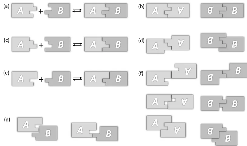
µm). However, the quality of the chains was low: they exhibited complete breaks (as in Figure II-1b) or dislocated bonds (with edges in partial contact, as in Figure II-1e) and the bonds between origami occurred in all four possible orientations (as in Figure II-1e). We hypothesized that three factors might be responsible: (1) the sequence of blunt-end base pairs was random, (2) the origami had a large global twist, and (3) the blunt ends had a crossover geometry incompatible with B-form stacking. We reduced or eliminated all three factors, demonstrated that at least (2) and (3) were contributing to the low quality of chains, and obtained straight linear chains with only two orientations. Details of these three factors are discussed in the following sections.
II.2.1.1.
DNA sequence at blunt ends
13
Figure II-1.Stacking of rectangles. (a) A long scaffold strand (black) is folded by multiple short staple strands to form a rectangle; features include edge staples (blue and red), interior staples (gray), dumbbell hairpins (orange ovals), and single-stranded loopouts (black bulges). The gray box indicates an area enlarged in (f). Each column of staples was originally 16 nt wide5; in twist-corrected rectangles, columns with base
deletions (pink) are 15 nt wide. (b,c) AFM comparison of rectangle chains without (b) and with (c) twist correction, deposited on mica. Upper left insets show models of single rectangles. Lower right inset (b) models how periodic breaks arise in a twisted chain during deposition. (d) Proposed structure of a stressed edge. (e) Model and AFM of rectangles with stressed edges. Solid vertical bars indicate that no stacking polarity is expected. Dashed vertical arrows emphasize that edges do not bond in an exclusively antiparallel orientation, as exemplified by rectangles related by 180° horizontal or vertical flips (indicated by half-circle arrows with an in-plane axis of rotation). (f) Proposed structure of a relaxed edge. (g) Model and AFM of rectangles with relaxed edges. Vertical arrows label stacking polarity; only “antiparallel” bonds form. Half-circle arrows indicate 180° rotation (about an axis going into the plane through the center of a bond). Scale bars in (b,c), 500 nm; in (e,g), 100 nm.
presented here, we decreased potential variability by placing a ‘GC’ base pair at each blunt end.
This was achieved by introducing single-stranded loopouts in the scaffold (Figure II-1a) to shift the scaffold sequence until a ‘GC’ occurred at the adjacent pair of blunt ends. A detailed procedure of
generating single-stranded loopouts in the scaffold is described in Materials and Methods (see the section for “Design of origami”).
II.2.1.2.
G
lobal twist
B-form DNA has a helical twist of 10.4 bp/turn67. The original rectangles1 were designed
case ofN¼4 andM¼3 with 34¼81 bond types was explored. This
approach is not reprogrammable (each origami is ‘hard-coded’; a unique origami must be synthesized for each shape), but it is exper-imentally simpler. In both systems, symmetry and mismatch con-straints limit the number of bond types and size of orthogonal sets. Non-idealities, such as the flexibility of edges, further decrease the number of usable bond types. We demonstrate the combination of origami using orthogonal sets of up to four distinct bond types. Finally, we use both systems to control thecis/transgeometry of multi-origami structures.
Results and discussion
Stacking of origami rectangles.We first explored stacking using a rectangular origami with 24 blunt ends along each edge (Fig. 1a). Approximately 200 staple strands (typically 32
nucleotides) were used to fold a scaffold strand (!7,000
nucleotides) into the desired shape. An L-shaped pattern of dumbbell hairpins5was added to provide height contrast under
atomic force microscopy (AFM). Crossovers are positions at which a strand jumps from one helix to another.
Previously, we observed stacking of similar 24-helix rectangles into long chains (up to 5mm) (ref. 5). However, the quality of the chains was low: they exhibited complete breaks (as in Fig. 1b) or dis-located bonds (with edges in partial contact, as in Fig. 1e) and the bonds between origami occurred in all four possible orientations (as in Fig. 1e). We hypothesized that three factors might be respon-sible: (1) the sequence of blunt-end base pairs was random, (2) the origami had a large global twist and (3) the blunt ends had a cross-over geometry incompatible with B-form stacking. We reduced or eliminated all three factors, demonstrated that at least (2) and (3) contributed to the low quality of chains, and obtained straight linear chains with only two orientations.
Regarding (1), the sequence at blunt ends: in principle, the strength of stacking bonds with random blunt-end sequences could vary by a factor of!11 (22.17/20.19) for all ‘GC’ versus all ‘AT’ pairs. Thus, in all the experiments presented here, we decreased potential variability by placing a ‘GC’ base pair at each blunt end. This was achieved by introducing single-stranded loopouts in the scaffold (Fig. 1a) to shift the scaffold sequence until a ‘GC’ occurred at the adjacent pair of blunt ends (Supplementary Note S2.4).
Regarding (2), the global twist: B-form DNA has a helical twist of 10.4 base pairs/turn (bp/turn) (ref. 32). The original rectangles5
were designed using a helical twist of 10.67 bp/turn, which was found to induce a significant global twist (recently studied in detail33,34). Here, we achieved an average helical twist of
10.44 bp/turn by deleting one base from every third column of staples (Fig. 1a) using our design code or caDNAno (ref. 35). Two AFM images show the difference in quality between chains formed by rectangles without (Fig. 1b) and with (Fig. 1c) twist cor-rection when deposited on mica. Whereas chains of twisted origami break with a characteristic offset (with a chirality consistent with a right-handed superhelix) every 2–6 origami, chains of twist-corrected origami exhibit rare breaks. For twisted and twist-twist-corrected origami, factors (1) and (3) were minimized by design.
Regarding (3), the crossover geometry at blunt ends: in general, we expect deviations from the B-form to weaken stacking23. The
original rectangles were designed with a set of edge staples that resulted in a crossover at every available location between adjacent blunt ends (Fig. 1d). In such edges, a conflict may arise because (i) the simultaneous presence of the scaffold and staple crossovers pulls the phosphates of scaffold and staples towards positions
1808 away from each other and (ii) the major–minor groove
relationship of a B-form base pair naturally places the phosphates
15nt 16nt
10.67bp/turn
v-flip h-flip
h2t h2t rot Base deletion columns
d e f
b Single-stranded loopouts c 10.44bp/turn a Dumbbell hairpin +
h2t h2t rot rot rot
g
Figure 1 |Stacking of rectangles.a, A long scaffold strand (black) is folded by multiple short staple strands to form a rectangle; features include edge staples (blue and red), interior staples (grey), dumbbell hairpins (orange ovals) and single-stranded loopouts (black bulges). The grey box indicates an area enlarged in (f). Each column of staples was originally 16 nucleotides (nt) wide5; in twist-corrected rectangles, columns with base deletions (pink) are 15 nt wide.b,c, AFM comparison of rectangle chains without (b) and with (c) twist correction, deposited on mica. Upper left insets show models of single rectangles. Lower right inset (b) models how periodic breaks arise in a twisted chain during deposition.d, Proposed structure of a ‘stressed edge’.e, Model and AFM image of rectangles with ‘stressed edges’. Solid vertical bars indicate that no stacking polarity is expected. Dashed vertical arrows emphasize that edges do not bond in an exclusively antiparallel orientation, as exemplified by rectangles related by 1808horizontal or vertical flips (indicated by half-circle arrows with an in-plane axis of rotation). Rectangles bind in head-to-tail (h2t), rotated (rot), horizontally flipped (h-flip) and vertically flipped (v-flip) orientations.f, Proposed structure of a ‘relaxed edge’.
g, Model and AFM images of rectangles with ‘relaxed edges’ (a larger example shown inc). Vertical arrows label stacking polarity; only ‘antiparallel’ bonds form. Half-circle arrows indicate 1808rotation (about an axis going into the plane through the centre of a bond). Scale bars: 500 nm (b,c); 100 nm (e,g).
ARTICLES
NATURE CHEMISTRY DOI: 10.1038/NCHEM.107014
using a helical twist of 10.67 bp/turn, which turned out to induce a significant global twist (recently studied in detail17,68). Here, in order to achieve an average helical twist of 10.44 bp/turn, we deleted one base from every third column of staples (Figure II-1a) using our MATLAB design code or caDNAno69. Two AFM images show the difference in quality between chains formed by
rectangles without (Figure II-1b) and with (Figure II-1c) twist correction, when deposited on mica. While chains of twisted origami break with a characteristic offset (with a chirality consistent with a right-handed superhelix) every 2–6 origami, chains of twist-corrected origami exhibit rare breaks. More wide-field AFM images for twisted (Figure II-3d-i) and twist-corrected (Figure II-3a-c) rectangles are shown in Figure II-3. Twisted and twist-corrected origami have factors (1), DNA sequence, and (3), crossover geometry, at blunt ends minimized by design.
II.2.1.3.
Crossover geometry at blunt ends
II.2.1.3.1.
Stressed edges vs. relaxed edges
In general we expect deviations from B-form to weaken stacking61. The original rectangles
were designed with a set of edge staples that result in a crossover at every available location between adjacent blunt ends (Figure II-1d). In such edges, a conflict may arise because (i) the simultaneous presence of the scaffold and staple crossovers pull the phosphates of scaffold and staples towards positions 180°away from each other, and (ii) the major-minor groove relationship of a B-form base pair would naturally place the phosphates 150°apart. Thus stressed edges seem incompatible with any geometry in which all of the blunt ends are in native form, and they might be expected to weaken or otherwise change stacking. Many different non-B-form geometries could resolve the stress at such edges, including breakage of the final base pair or a change in major/minor groove angles; accurately predicting what happens lies beyond the state of the art.
We propose that near-flattening of the major and minor grooves decreases the distinction between them (Figure II-1d) and creates a top-bottom pseudosymmetry that prevents stacking from exhibiting a strongly preferred orientation. Experimentally, just such a promiscuity of orientation is observed: rectangles bind in head-to-tail (34% of total bonds), rotated (44%), horizontally flipped
15
Edge staples were redesigned so that there are no staple crossovers (Figure II-1f). In such
relaxed edges blunt ends are free to assume normal B-form groove angles. Rectangles with relaxed edges can bind via near-B-form stacking (see the subsection for “Models of edge structures” below) in head-to-tail and rotated orientations, but not in flipped orientations because of their strong top-bottom asymmetry. Our experiments are consistent with the hypothesis that near-B-form stacking is preferred; only head-to-tail (42% of total bonds) and rotated orientations (58%) are observed (N=318, Figure II-1g). Further, dislocations are exceedingly rare (1%). This is consistent with the idea that either (i) stacking bonds based on relaxed edges are stronger than those formed from stressed edges, or (ii) relaxed edges are more geometrically uniform (thus allowing any dislocated bonds that form as kinetic products to slide and become full bonds). Origami in Figure II-1e,g have factors (1), DNA sequence at blunt ends, and (2), global twist, minimized by design.
II.2.1.3.1.1.
Models of edge structures
Because accurate models of origami edges backed by high resolution structural data do not exist, it is difficult to predict the exact structure and stacking configurations of the blunt ends on the edges of origami. Here we provide gross predictions based on the distance of the blunt ends from the nearest internal crossovers and the pattern of crossovers along the edge. We predict structures for three different edge models: (1) a crossover-free edge (Figure II-2a), (2) a relaxed edge with only scaffold crossovers (Figure II-2b), and (3) a stressed edge with both scaffold and staple crossovers (Figure II-2c). These predicted structures in turn imply predictions about the expected strength and behavior of the stacking bonds.
16
Figure II-2.Comparative modeling of three different origami edge structures. (a) Crossover-free edges. (b) Relaxed edges with only scaffold crossovers. (c) Stressed edges with both scaffold and staple crossovers. Each circle indicates a blunt end. In (a), both the black and colored bars (inside the circles) indicate the helical twist of bases belonging to tile adapter strands. In general, tile adapter strands are strands that extend from the edge of an origami to give it a geometry that is not possible using the canonical scaffold/staple geometry. Here, our intent is that the tile adapter strands create a crossover-free edge; we do not show the details and did not use them in our stacking experiments. Here we use them as part of a “thought experiment” concerning the geometry of stacking bonds, but we note that tile adapter strands have been used to create origami with a very similar crossover-free edges49. In (b) and (c), black bars indicate the helical twist of bases from the scaffold
strand, and colored bars indicate the helical twist of bases from the staple strands. Bars of the same color indicate the same strand, e.g., the orange staple in (a) runs for 1.5 helical turns in one helix, switches between helices at a 16-bp-deep internal crossover, and runs back for a length of 1.5 helical turns in the adjacent helix, as depicted by the three-dimensional drawing. Black dotted arrows indicate crossovers at the edge. In all three models, colored strands are intended to make 16-bp-deep internal crossovers. The models in (a-c), predict that the blunt ends on the edge are either B-form (a), near-B-form (b), or have disrupted base pairs that are incompatible with B-form geometry (c). (d-f) show models of the juxtaposition that occurs when two different origami edges form a stacking bond; these bonding models correspond to the edge structure models in (a), (b), and (c), respectively. Models (d) and (e) make predictions for the relative helical twist between blunt ends across the bond. Model (f) suggests that the disturbance of the base pairs at the edge of the origami may decrease the distinction between the major and minor grooves enough to create a top-bottom pseudosymmetry. This pseudosymmetry could allow bonding between origami in one of the flipped orientations (not shown).
edge, the base pairs at the blunt end would be oriented like those depicted in Figure II-2a. We note that while we do not make such a structure in this work, origami with very similar crossover-free edges have been made before51 using “tile adapters”, and so such structures can be experimentally synthesized.
Now consider a second origami with the same crossover-free edge structure, but with 15 base
No crossover
Only scaffold crossovers (relaxed edge)
Scaffold+staple crossovers (stressed edge) (a)
(b)
(c)
(d)
(e)
(f)
17
pairs between the edge and the crossover. When such an origami binds via a stacking bond to the origami described above, then the total number of base pairs between the first internal crossover points of the two origami will be 15+16 = 31, or roughly 3 helical turns. This means that for such crossover-free origami, the blunt ends on opposite sides of the stacking bond are oriented with a relative twist angle of ~34.6° (as depicted in Figure II-2d). Thus we would expect stacking of blunt ends between crossover-free edges to be native B-form stacking, and that it should be relatively strong.
Next consider our second edge structure, the relaxed edges (Figure II-2b), for which scaffold crossovers connect every other pair of helices. This is the edge structure that we use in all our work on stacking bonds, except for structures pictured in Figure II-1e and Figure II-3j-o. Because the scaffold crossovers act to pull the base pairs away from the helical twist angle that they would assume in a crossover-free edge, whatever structure forms at relaxed edges cannot be B-form DNA. However, because DNA can tolerate small deviations from B-form twist, we propose that the helices assume an amount of twist strain (roughly 34.6°, which is averaged over the 16 base pairs up to the crossover) and maintain native major/minor groove angles between the bases at the blunt end (depicted in Figure II-2b).
Given our model for relaxed edges, when two origami with relaxed edges bind via a stacking bond, their blunt ends will not be able to stack via B-form stacking; rather, they should bind with slightly different relative twist angles that are within approximately ±34.6° of the natural twist angle in B-DNA (Figure II-2e). We call such stacking between relaxed edges “near-B-form stacking”, which we predict would be roughly as strong as B-form stacking. Since relaxed edges have a top-bottom asymmetry that is defined by the major and minor grooves, near-B-form stacking can only occur when two origami bind in either the head-to-tail or rotated orientations. This prediction agrees well with the distribution of observed bond orientations, as discussed above.
18
(Figure caption on next page)
(a)
(b)
(c)
(d)
(e)
(f)
(g)
(h)
(i)
(j)
(k)
(l)
19
Figure II-3.Wide-field AFM images of rectangle origami systems. (a-c) Twist-corrected origami with relaxed edges. Note that they form chains with lengths on the order of ~10 um. Chains formed by these origami break in a way that suggests that the breakage occurs upon deposition since pieces lie close to each other. However, in contrast to the twisted origami shown in (d-i), twist-corrected origami break into long pieces and show no preferred direction for the shift between neighboring pieces. Note also that twist-corrected relaxed chains are straight with very rare dislocations, as opposed to the twist-corrected origami with stressed edges shown in (j-o). (d-i) Twisted origami (with relaxed edges). Chains break with a characteristic periodicity (2-6 origami) and directional offset. Note that some parts of the chains seem to unwind while depositing, especially near the ends (as suggested by the straight sections near the ends of twisted chains). (j-o) Origami with stressed edges (with twist-correction). Bonds are promiscuous: many dislocations occur and the bond orientations are random. Orange boxes and arrows show zoom-in areas. Scale bars in (a), (c), (j), (l),
(m), (o) are 600 nm, and scale bars in (b), (d-i), (k), (n) are 1 µm.
II.2.1.3.2.
Anti-parallelism of stacking bonds
The asymmetry of relaxed edges gives stacking bonds an interesting and important property analogous to the antiparallel nature of DNA hybridization: if we label relaxed edges with arrows according to their asymmetry, we see that two edges form a bond only if the arrows point in opposite directions. Thus the arrows define an antiparallel stacking polarity. We label edges such that when the major grooves at an edge point up, the arrow’s direction matches the 5’ to 3’ polarity of the scaffold at the edge (as shown in models in Figure II-1g). Stacking polarity allows stacking bonds to specify unique products by breaking the symmetry of otherwise symmetric bonds.
II.2.2.
Two approaches
towards
specific stacking bonds
II.2.2.1.
Binary codes
II.2.2.1.1.
Key concepts
Stacking between two origami edges can be largely abolished by omitting their edge staples1: each omitted staple prevents the formation of two blunt ends and leaves a 32-nt
single-stranded scaffold loop. Sufficient complementarity between such loops could allow them to associate. For the M13mp18-based designs used so far, origami without edge staples do not aggregate, suggesting that scaffold loops may act primarily as entropic brushes with no affinity71.