127 | P a g e
DIE LESS SINGLE POINT INCREMENTAL FORMING
PROCESS OF AA6082 SHEET METAL TO DRAW
PARABOLIC CUPS USING ABAQUS
1
K. Sai Santosh Kumar,
2A. Chennakesava Reddy
1
PG Student,
2Professor
Department of Mechanical Engineering, JNT University, Hyderabad, (India)
ABSTRACT
Aim of the current project work was to decide the formability of AA6082 alloy to manufacture parabola cups using single point incremental forming (SPIF) process. The finite element analysis has been carried out to model the single point incremental forming process using ABAQUS software code. The process variables of SPIF were sheet thickness, step depth, tool radius and coefficient of friction. The process variables have been optimized using Taguchi techniques. The major process variables influencing the SPIF of parabola cups were sheet thickness and step size.
Keywords:
AA6082 alloy, parabola cup, single point incremental forming, finite element analysis,
step depth, tool radius, sheet thickness, coefficient of friction.
I. INTRODUCTION
Deep drawing process is extensively employed for variety of cups using sheet materials by dies. In a series of
research on deep drawing process to fabricate variety of cup shapes, rich investigation have been carried out to
improve the super plastic properties of materials such as AA1050 alloy [1], AA2017 alloy [2], AA3003 alloy
[3], AA5049 alloy [4], Ti-Al-4V alloy [5], gas cylinder steel [6]. Matsubara in [7] analyzed numerically
controlled (NC) machine tool for forming flat metal sheets into convex shapes. In single point incremental
forming (SPIF) process, the sheet material is clamped along its edges and a hemispherical headed tool is moved
along a predefined geometrical path so that it deforms the sheet locally along the path. The important process
variables, which impact the SPIF process capability, are tool diameter, step depth, feed rate, rotational speed of
the spindle, sheet thickness, lubrication and tool path [8-13].
The current work was to study the formability of parabola cups of AA6082 alloy using SPIF. For this purpose
the design of experiments was executed as per Taguchi technique. The process parameters of SPIF were sheet
thickness, step depth, tool radius and coefficient of friction. The formability was evaluated using finite element
method.
II. MATERIAL AND METHODS
In the present work, ABAQUS (6.14) software code was used for the numerical simulation of SPIF process to
fabricate parabola cups. The material was AA6082 alloy. The SPIF process parameters were chosen at three
levels as summarized in table 1. The orthogonal array (OA), L9 was preferred to carry out experimental and
128 | P a g e
Table 1: Process parameters and levelsFactor Symbol Level–1 Level–2 Level–3
Sheet thickness, mm A 1.0 1.2 1.5
Step depth, mm B 0.50 0.75 1.00
Tool radius, mm C 4.0 5.0 6.0
Coefficient of friction D 0.05 0.10 0.15
The sheet and tool geometry were modeled as deformable and analytical rigid bodies, respectively, using
ABAQUS. They were assembled as frictional contact bodies. The sheet material was meshed with S4R shell
elements. The fixed boundary conditions were given to all four edges of the sheet. The boundary conditions for
tool were x, y, z linear movements and rotation about the axis of tool. True stress-true strain experimental data
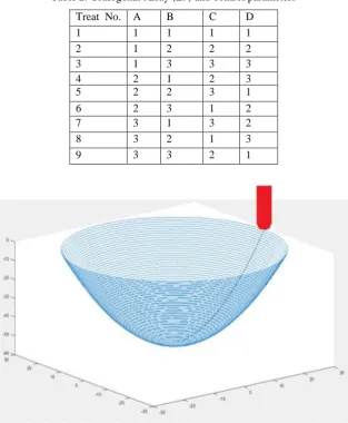
were loaded in the tabular form as material properties. The tool path geometry was generated using CAM
software [14] was imported to the ABAQUS as shown in figure 1. The elastic-plastic deformation analysis was
carried out for the equivalent stress, strain and strain rates and thickness variation.
Table 2: Orthogonal Array (L9) and control parameters
Treat No.
No.
A B C D
1 1 1 1 1
2 1 2 2 2
3 1 3 3 3
4 2 1 2 3
5 2 2 3 1
6 2 3 1 2
7 3 1 3 2
8 3 2 1 3
9 3 3 2 1
129 | P a g e
The influence of process variables on the von Mises stress, strain rate and thickness reduction are debated. Theformability limit diagrams are also created.
3.1 Influence of process parameters on effective stress
Table 3 gives the ANOVA (analysis of variation) summary of von Mises stress data. The percent contribution
specifies that sheet thickness, A legacies 66.08%, step depth, B contributes 15.64%, tool radius, C gives 8.42%
and coefficient of friction, D adds 9.87% of total variation on the von Mises stress.
Table 3: ANOVA Summary of the Effective Stress.
Source Sum 1 Sum 2 Sum 3 SS v V P
A 1262.57 1350.88 1361.91 1976.54 2 988.27 66.08
B 1339.83 1294.53 1340.98 467.89 2 233.94 15.64
C 1344.94 1306.10 1324.31 251.74 2 125.87 8.42
D 1335.41 1300.91 1339.03 295.10 2 147.55 9.87
e 0.00 0 0.00
T 5282.75 5252.43 5366.23 2991.26 8 100.00
Note: SS is the sum of square, v is the degrees of freedom, V is the variance, P is the percentage of contribution
and T is the sum squares due to total variation.
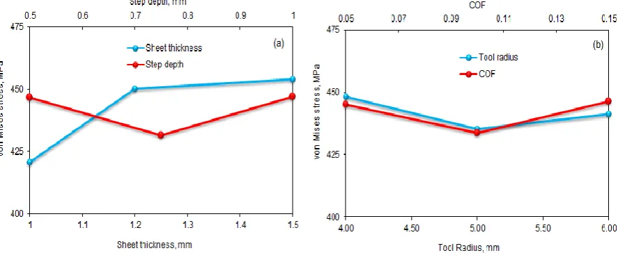
Fig.2 presents the influence of SPIF process variables von Mises stress induced in AA6082 alloy. The von
Mises stress is increased with increase of sheet thickness (Fig.2a). As the thickness of sheet increases the force
required to undergo plastic deformation of the sheet materials also increases. Hence, an increase in the von
Mises stress. Also, Fig.2a defines the von Mises stress as a function of step depth. The von Mises stress
decreases initially with decrease of step depth from 0.5 to 0.75 and later on it increases for a change in step
depth from 0.75 to 1.0 mm. The von Mises stress is minimum for tool radius of 5 mm and friction coefficient of
0.15 as shown in Fig.2b.
130 | P a g e
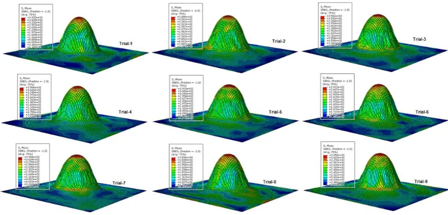
Figure 3: Effect of equivalent plastic strain of von Mises stress
For the trials 1, 2 and 3, the von Mises stresses are, respectively, 393.5, 388.4 and 391.6 MPa. For the trials 4, 5
and 6, the von Mises stresses are, respectively, 395.4, 393.3 and 393.3 MPa. For the trials 7, 8 and 9, the von
Mises stresses are, respectively, 395.4, 393.6 and 395.4 MPa. The ultimate tensile strength of AA6082-T6 alloy
is 300 MPa which exceeds in all the cases (figure 4).
131 | P a g e
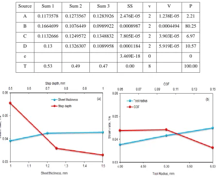
The ANOVA summary of the strain rate is given in Table 4. The percent contribution column establishes themajor contributions 2.21%, 80.25%, 6.97% and 10.57% of sheet thickness, step depth, tool radius and
coefficient of friction, respectively, towards variation in the strain rate.
Table 4: ANOVA summary of the strain rate
Source Sum 1 Sum 2 Sum 3 SS v V P
A 0.1173578 0.1273567 0.1283926 2.476E-05 2 1.238E-05 2.21
B 0.1664699 0.1076449 0.0989922 0.0008987 2 0.0004494 80.25
C 0.1132666 0.1249572 0.1348832 7.805E-05 2 3.903E-05 6.97
D 0.13 0.1326307 0.1089958 0.0001184 2 5.919E-05 10.57
e 3.469E-18 0 0
T 0.53 0.49 0.47 0.00 8 100.00
Figure 5: Influence of process parameters on strain rate.
The strain rate increases with increase of sheet thickness (Fig.5a) and tool radius (Fig.5b). The strain rate is
decreased with increase of step depth (Fig.5a) and coefficient of friction (Fig.5b). For smaller step size local
deformation plays an important role than stretching. As the tool radius increases, the area under the tool exposed
to the plastic deformation also increases. Hence, increase in tool radius enhances the strain rate. The cup
formation depends on the shear stress developed during the plastic deformation of sheet material. The frictional
shear stress is directly proportional to the coefficient of friction as per Coulomb's law of friction ( ,
where Fn is the normal pressure).
3.3 Influence of parameters on thickness reduction
The ANOVA summary of the thickness reduction is given in Table 5. The thickness reduction during the cup
drawing is only dependent on sheet thickness only. The other process variables have negligible influence on the
132 | P a g e
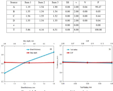
Table 5: ANOVA summary of the thickness reductionSource Sum 1 Sum 2 Sum 3 SS v V P
A 1.19 1.54 1.90 0.08 2.00 0.04 99.47
B 1.55 1.54 1.54 0.00 2.00 0.00 0.05
C 1.56 1.55 1.52 0.00 2.00 0.00 0.44
D 1.55 1.54 1.55 0.00 2.00 0.00 0.04
e 0.00 0.00 0.00
T 5.86 6.16 6.51 0.08 8.00 100.00
Figure 6: Influence of process parameters on thickness reduction.
133 | P a g e
reduction of thickness was considered at the center-line of the deformed cup as shown in Fig.7. As observedfrom Fig.7, the majority of thickness reduction takes place in the walls of the cup but not in the flange or bottom
of the cup. The elements located at the mid regions of the walls are elongated higher than those present at the
top and bottom of the cup walls.
Figure 8: Forming limit diagrams: (a) for trials 1, 2, 3 (b) for trials 4, 5, 6 (c) for trials 7, 8, 9.
3.4 Formability of SPIF process
The formability diagrams of the cups are shown in Fig.8. During initial stages of SPIF, the shear and
compressive stresses were dominating the formability of parabola cups of AA6082 alloy. At later stages of
plastic deformation the tension is highly predominant resulting the stretching of sheet.
IV. CONCLUSIONS
The major SPIF process parameters which influence the formability of parabola cups of AA6082 alloy were
sheet thickness and step depth. The optimal process parameters could be sheet thickness of 1.5 mm, step depth
134 | P a g e
REFERENCES
[1] A. C. Reddy, "Formability of Warm Deep Drawing Process for AA1050-H18 Pyramidal Cups,"
International Journal of Science and Research, vol. 4, no.7, pp. 2111-2119, 2015.
[2] A. C. Reddy, "Finite Element Analysis of Warm Deep Drawing Process for 2017T4 Aluminum Alloy:
Parametric Significance Using Taguchi Technique,” International Journal of Advanced Research, vol. 3,
no. 5, pp. 1247-1255, 2015.
[3] A. C. Reddy, "Practicability of High Temperature and High Strain Rate Superplastic Deep Drawing
Process for AA3003 Alloy Cylindrical Cups," International Journal of Engineering Inventions, vol. 5, no.
3, pp. 16-23, 2016.
[4] A. C. Reddy, "High temperature and high strain rate superplastic deep drawing process for AA5049 alloy
cylindrical cups," International Journal of Engineering Sciences & Research Technology, vol. 5, no.2, pp.
261-268, 2016.
[5] A.C. Reddy, "Finite element analysis of reverse superplastic blow forming of Ti-Al-4V alloy for
optimized control of thickness variation using ABAQUS," Journal of Manufacturing Engineering, vol. 1,
no.1, pp.6-9, 2006.
[6] A. C .Reddy, "Evaluation of local thinning during cup drawing of gas cylinder steel using isotropic
criteria," International Journal of Engineering and Materials Sciences, vol. 5, no.2, pp.71-76, 2012.
[7] S. Matsubara, A computer numerically controlled dieless incremental forming of a sheet metal,
Proceedings of the Institution of Mechanical Engineers, Part B: Journal of Eng. Manufacture, Vol. 215,
No. 7, pp. 959-966, 2001.
[8] V. Srija, A. C. Reddy, “Numerical Simulation of Truncated Pyramidal Cups of AA1050-H18 Alloy
Fabricated by Single Point Incremental Forming,” International Journal of Engineering Sciences &
Research Technology, vol. 5, no. 6, pp. 741-749, 2016.
[9] T. Santhosh Kumar, A. C. Reddy, “Single Point Incremental Forming and Significance of its Process
Parameters on Formability of Conical Cups Fabricated From AA1100-H18 Alloy, International Journal
of Engineering Inventions,” vol. 5, no. 6, pp. 10-18, 2016.
[10] A. Raviteja, A. C. Reddy, “Implication of Process Parameters of Single Point Incremental Forming for
Conical Frustum Cups From AA 1070 using FEA,” International Journal of Research in Engineering and
Technology, vol. 5, no.6, pp. 124-129, 2016.
[11] T. Santhosh Kumar, V. Srija, A. Ravi Teja, A. C. Reddy, “Influence of Process Parameters of Single
Point incremental Deep Drawing Process for Truncated Pyramidal Cups from 304 Stainless Steel using
FEA,” International Journal of Scientific & Engineering Research, vol. 7, no. 6, pp. 100-105, 2016.
[12] C. R. Alavala, “FEM Analysis of Single Point Incremental Forming Process and Validation with
Grid-Based Experimental Deformation Analysis,” International Journal of Mechanical Engineering, vol. 5, no.
5, pp. 1-6, 2016.
[13] C. R. Alavala, “Validation of Single Point Incremental Forming Process for Deep Drawn Pyramidal Cups
using Experimental Grid-Based Deformation,” International Journal of Engineering Sciences & Research
Technology, vol. 5, no. 8, pp. 481-488, 2016.