263 | P a g e
EVALUATION OF MECHANICAL PROPERTIES OF
POLYMER COMPOSITE MATERIALS
Vishwanatha N.R
1,Rani R
2,Chaithra K.N
3,
1
Assistant Professor, Dept. of Mechanical Engineering, NDRKIT, Hassan, Karnataka, India
2
Assistant Professor, Dept. of Mechanical Engineering, NDRKIT, Hassan, Karnataka, India
3
Lecturer, Dept. of Mechanical Engineering, Rajeev polytechnic, Hassan, Karnataka,India
ABSTRACT
Composite material are engineering materials made from two or more constituent materials, which are distinct in physical or chemical properties, which remain, separate and distinct on a macroscopic level within the finished structure.
The present experimental work deals with the study of mechanical properties of glass fiber reinforced polymer with vinyl ester resin and silicon dioxide filler particles. Glass fiber mat of 360 gsm and silicon dioxide of size 40 to 150 mesh is used. Laminates are prepared by using Hand lay-up method. Laminates are cured in hot air oven at 800C about one hour for better curing. Specimens for tensile, flexural and impact test were cut from the fabricated laminate according to the ASTM standards and are tested. The result showed that the Ultimate tensile strength of the laminate with 5, 10, wt% silicon dioxide filler exhibit lower tensile strength till 5% as compared to unfilled composites and then increases. For bending test, the laminate with 5, 10% silicon dioxide filler exhibit higher flexural strength than unfilled composite at constant position and load condition and in impact test the laminate with 5, 10% silicon dioxide filler exhibit higher impact strength than unfilled composite.
I. INTRODUCTION
1.1 Composite Materials
A composite material is defined as a combination of two or more materials that results in better properties than
when the individual components are used alone. Composite materials are consisting of one or more
discontinuous phases embedded in a continuous phase. The discontinuous phases are usually harder and stronger
than the continuous phases and are called the „reinforcements„ or „reinforcing materials‟ whereas the continuous
phase is termed as the „ matrix‟ which is more ductile and less hard. The reinforcements serve to strengthen the
composites and improve the overall mechanical properties of the matrix. Properties of composites are strongly
dependent on the properties of their constituent materials, their distribution and the interaction among them.
II. MATERIALS
2.2
Reinforcement materials
264 | P a g e
2.2.1 Glass fiberGlass fiber is a material consisting of numerous extremely fine fibers of glass. It is used as a reinforcing agent
for many polymer products, to form a very strong and light fiber reinforced polymer (FRP) composite material
called glass reinforced plastic (GRP), popularly known as “fiber glass”. Glass fiber mat of 360 gsm is as shown in figure 2.1 and also specification of glass fiber mat is as shown in table 2.1.
Specification of glass fiber mat
Figure 2.1: Glass fiber mat of 360 gsm
Table 2.1: Specification of glass fiber mat
2.2.2 Filler material
In this study, silicon dioxide (figure 2.2) with an particle size of 40 to 150 mesh were used as filler in 5%wt,
10%wt, with respect to weight of vinyl ester resin.
Silicon dioxide, also known as silica (from the Latin silex), is a chemical compound that is a dioxide of silicon
with the chemical formula SiO2. Silica is most commonly found in nature as quartz. Silica is one of the most
complex and most abundant families of materials, existing both as several minerals and being produced
synthetically. Notable examples include fused quartz, crystal, fumed silica, silica gel, and aero gels.
Applications range from structural materials to microelectronics to components used in the food industry.
Specification of silicon dioxide filler
Product E-glass fabric
Product
family Plain woven
Manufacturer Owens Corning (OCV) Technical Fabrics, India
Total weight
(g/m2) 360
Fabric width
(m)
265 | P a g e
Figure 2.2: Silicon dioxide
Table 2.2: Specification of silicon dioxide filler
2.3 Resin System
The resin system consists of vinyl ester (figure 2.3) with its 2% of catalyst, promoter, accelerator. Vinyl ester
resins are unsaturated resins prepared by the reaction of a monofunctional unsaturated acid, such as methacrylic
or acrylic, with a bisphenol diepoxide. The resulting polymer is mixed with an unsaturated monomer, such as
styrene. The handling and performance characteristics of vinyl esters are similar to polyesters. Some advantages
of the vinyl esters, which may justify their higher cost, include superior corrosion resistance, hydrolytic stability,
and excellent physical properties, such as impact and fatigue resistance. It has been shown that a 20 to 60 mil
layer with a vinyl ester resin matrix can provide an excellent permeation barrier to resist blistering in marine
laminates. Specification is as shown in below table 2.3.
Product Silicon dioxide (extra pure)
Manufacturer Loba Chemie Pvt. Ltd., Mumbai, India
Molecular formula SiO2
Molecular weight 60.08
Physical state Crystalline powder
Colour/odour White/odourless
Particle size 40-150 mesh
Boiling point 2230oC
Melting point 1710oC
Specific
gravity/density
2.20 g/cm3
Chemical stability Stable under normal temperatures and pressures
266 | P a g e
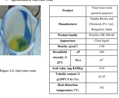
Specification of vinyl ester resin
Figure 2.3: vinyl ester resin
Table 2.3: Specification of vinyl ester resin
Features of vinyl ester resin
Vinyl ester combines inherent toughness with outstanding heat and chemical resistance. Corrosion-resistance.
Possesses low ester content and low unsaturation resulting in greater resistance to hydrolysis and less
shrinkage during cure.
High resistance to micro fracturing and shrinkage.
III.
SPECIMEN PREPARATION
3.1. Fabrication process
Figure 3.1: Basic procedure of hand lay- up technique
Fabrication is defined as the process of converting raw materials into finished products. Fabrication process is
done by using Hand lay-up method. Hand lay-up molding is the method of laying down fabrics made of
reinforcement and painting with the matrix resin layer by layer until the desired thickness is obtained.
The glass fiber mat of size 250×250mm is used for fabrication of laminates. Release film was laid on the surface
of the mold and release spray is sprayed to facilitate easy removal of the laminate after curing. The glass fiber
mats are laid on the surface of the mold. Figure 3.2 shows the step by step fabrication process. Product Vinyl ester resin
(general-purpose)
Manufacturer
Naptha Resins and
Chemicals Pvt. Ltd.,
Bangalore, India
Product family Polyflex GR 200-60
Appearance Clear liquid
Density (g/cm3) 1.06
Brookfield
viscosity @
25oC
cP 440
Pa-s 10-3
Acid value (mg KOH/g) 9.65
Volatile content (2
g/150oC/1 h) (%) 42.45
Heat distortion
267 | P a g e
a) Mold b) Applying release spray to the release film
c) Applying resin on the mat d) Applying load
e) Curing in oven f) Cured plate
Figure 3.2: Fabrication Process
The resin, catalyst, promoter and accelerator mixture is applied on both surface of the glass fiber mat using
brush, the same mixture is uniformly distributed throughout the glass fiber mat and the procedure is continued
for all next layers of glass fiber mat and the mold is then closed and load is applied for about 24hrs for curing.
Plates are prepared with 0%, 5% and 10% of silicon dioxide filler materials using By-mass method. Plates are
again cured at 800C using oven.
For the preparation of particle filled glass fiber reinforced vinyl ester composites, silicon dioxide filler particles
are added to the above mixture, the composite specimen with two different filler proportions are prepared. The
weight fractions of the filler in the matrix were 5%, 10% with respect to the weight fraction of the vinyl ester
resin.
66.67 gram of resin is added for each 100 gram of glass fibre. Resin system consists of vinyl ester resin with its
2% of catalyst, promoter and accelerator.
The weight fraction of fiber and filler in the finished laminate is calculated using the equation
W = Wt / Wfl
Where, Wfiber= Weight fraction of fiber, %
Wt= Total weight of mats, grams
268 | P a g e
3.2 Preparation of samples
All samples are prepared according to American Standard for Test Methods (ASTM)
3.2.1. Tensile Test Specimen
According to ASTM D 638, the specimen is cut into required dimension (175× 20×5 ) using jig saw and is
finished to size using emery paper. Aluminum end tabs are mounted at both ends of the specimen for the
purpose of gripping. The geometry of the test specimen is shown in figure 3.1
3.2.2. Flexural Test Specimen
According to ASTM D790, the specimen is cut into required dimension (150×12.7×10) using jig saw and is
finished to size using emery paper. The geometry of the test specimen is shown in figure 3.2
3.2.3. Impact Test Specimen
Izod Test Specimen
According to ASTM D 256, the Izod specimen is cut into required dimension (64×12×3.2) using jig saw and is
269 | P a g e
IV. EXPERIMENTATION
4.1 Tension Test
Figure 4.1 shows tensile specimen of GFRP composite whose ends are gripped into universal testing machine
with a capacity of 100 KN. Extensometer is fitted to test specimen which measures extension over the length of
the specimen. The sample is loaded along the fiber direction gradually and at regular intervals of loads extension
is measured. After certain load extension increases at faster rate and the capacity of extensometer to measure
extension comes to an end and hence, it is removed before this stage is reached and extension is measured from
scale on the UTM. Load is increased gradually till the specimen breaks. For each composition, three identical
specimens are tested and average results are reported. The load v/s deflection values are noted and stress v/s
strain graphs are plotted.
Figure 4.1: Tensile test setup
4.2 Flexural Test
The flexural test measures the force required to bend a beam under three point loading conditions. The specimen
lies on a support span and the load is applied to the center by the loading nose producing three points bending at
a specified rate. The parameters for this test are the support span, the speed of the loading, and the maximum
deflection for the test.
The 3- point bend test is conducted as per ASTM standard D790 using UTM. The data recorded during the test
is used to evaluate the flexural strength.
270 | P a g e
4.3 Impact Test
Izod Test
The impact properties of the material are directly related to the overall toughness which is defined as the ability
to absorb applied energy. Impact strength is a measure of toughness. In this research, pendulum impact test –
Notched Izod Impact Test is utilized. Figure 4.3 shows Izod testing machine.
Figure 4.3: Impact testing machine ( Izod test )
4.4 Results And Discussions
In this section the experimental results obtained for the tensile, bending and impact tests were discussed.
4.4.1. Tensile strength
Since composites are brittle materials they manifest only macroscopic elastic deformation up to the stress at
which they fails. These materials follow linear elastic stress-strain relations up to their fracture. The stress-strain
diagram and load v/s displacement diagram for these composites are as shown in figure 4.4(a) to figure 4.4(h),
all curves indicate non-linear behavior. The point of deviation from linearity is the indication of failure initiation
due to development of crack on the tension side. Young‟s modulus is determined from the slope of the
stress-strain curve within the elastic limit.
Figure 4.4(a): Stress v/s Strain graph for unfilled Figure 4.4(b): Stress v/s Strain graph for 5% filled
specimens specimens Strain
in%
Str
ess
in
M
P
a
Str
ess
in
M
P
a
271 | P a g e
Figure 4.4(c): Stress v/s Strain graph for 10% filled Figure 4.4(d): Stress v/s Strain graph for different
specimens combinations
Figure 4.4(e): Load v/s displacement graph for unfilled Figure 4.4(f): Load v/s displacement graph for 5%
filled specimens specimens
Strain
in%
Str
ess
in
M
P
a
Displacement in mm
L
o
a
d in K
N
Displacement in mm
Displacement in mm
Str
ess
in
M
P
a
Strain in%
L
o
a
d in K
N
L
o
a
d in K
N
Displacement in mm
L
o
a
d in K
272 | P a g e
Figure 4.4 (g): Load v/s displacement graph for 10% filled Figure 4.4(h): Load v/s displacement graphfor different specimens combinations
270 275 280 285 290 295 300 305
0 5 10
Figure 4.4 (i): Tensile strength v/s wt% of silicon dioxide
Figure 4.4(i) shows the variation of ultimate tensile strength v/s wt% of silicon dioxide filler. The Ultimate
tensile strength of the laminate with 5, 10, wt% silicon dioxide filler exhibit lower tensile strength till 5% and
then increases. 0 5 10 15 20 25
0 5 10
Figure 4.4(j): Young’s modulus v/s wt% of silicon dioxide
The variations of tensile properties (Young‟s modulus, total percentage elongation) of the Glass-fiber reinforced
vinyl ester composites with silicon dioxide filler are shown in Figures 4.4(e)–4.4(f). It is clearly seen that weight
fractions of the silicon dioxide filler in the vinyl ester matrix appear to influence tensile properties. The Young‟s
modulus of the glass fiber reinforced vinyl ester composite was decreases with filler content upto 5% and then
increases. Yo un g s mo du lus i n G P a
Silicon dioxide in % Silicon dioxide in %
273 | P a g e
01 2 3 4 5
0 5 10
Figure 4.4(k): Elongation at Failure v/s wt% of silicon dioxide
Higher the filler percentage, higher is the agglomeration of SiO2 particles, thus reducing the tensile
strength. Young‟s modulus is mainly dependent on the matrix deformation of the composite and increases as the
slope of load-deformation curve at the initial stage and is practically not much influenced by the interfacial
strength between fiber and the matrix.
The tensile modulus of SiO2 filled composites increases as the wt. fraction of the filler increases. Again there is
a reduction in the elongation at break of the composites with increase in the wt. fraction of the filler. This is due
to the fact that the SiO2 filler is hard and also highly brittle. As the wt. fraction of SiO2 filler increase, the
tensile modulus of the filled composites increases, but at the same time the system becomes more brittle. The
increase in the tensile strength with wt. fraction of filler is attributed to the high modulus of ceramic filler which
are dispersed uniformly in the fabric layers of filled composites.
Percentage elongation at failure increases with increasing the silicon dioxide filler up to 5% and then decreases.
Since after certain limit the specimen becomes more brittle with the addition of silicon dioxide.
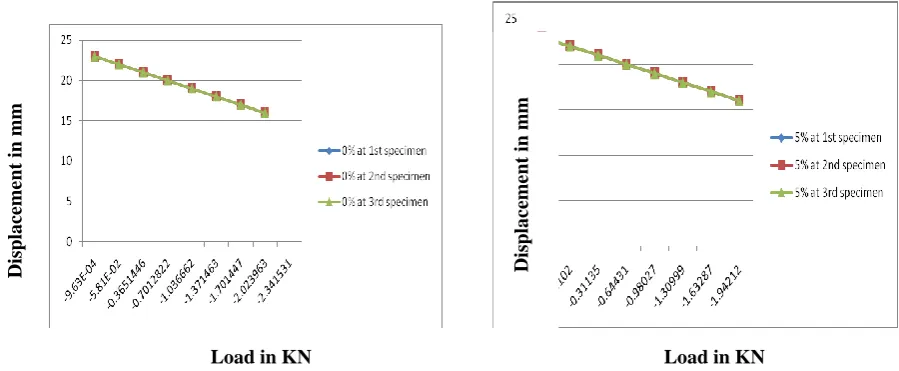
4.4.2 Flexural strength
Figure 4.5(a): Displacement v/s Load for unfilled Figure 4.5(b): Displacement v/s Load for 5% filled
specimens specimens Silicon dioxide in %
E
lo
ng
a
tio
n a
t
brea
k in %
Dis
pla
ce
me
nt
in mm
Load in KN Load in KN
Dis
pla
ce
me
nt
274 | P a g e
Figure 4.5(c): Displacement v/s Load for 10% filled Figure 4.5(d): Displacement v/s Load for different
specimens combinations
Figure 4.5 shows the variation of flexural strength v/s wt% of silicon dioxide filler. By observing
above graphs, the laminate with 5, 10 wt% silicon dioxide filler exhibit higher flexural strength than unfilled
composite at constant position and load condition. The flexural strength is found to increase with the increase in
filler content.
5.3. Impact strength
The izod impact strength v/s wt% of silicon dioxide diagram for these composites are shown in figure.
Figure 5.3(a) :Impact strength v/s wt% of silicon dioxide
Figure 5.3(a) shows the variation of impact strength v/s wt% of silicon dioxide filler. The laminate with 5, 10
wt% silicon dioxide filler exhibit higher impact strength than unfilled composite. The impact strength is found
to increase with the increase in filler content.
Dis
pla
ce
me
nt
in mm
Load in KN
Dis
pla
ce
me
nt
in mm
Load in KN
Silicon dioxide in %
Imp
a
ct
s
tre
ng
th in J
/m
m
275 | P a g e
VI. CONCLUSION
Effect of inclusion of silicon dioxide as filler material in glass/vinyl ester composites on tensile and impact test
has been investigated experimentally. Based on the results of investigation, following conclusions are made.
The Ultimate tensile strength of the laminate with 5, 10, wt% silicon dioxide filler exhibit lower tensile
strength till 5% and then increases.
By observing flexural strength graphs, the laminate with 5, 10 wt% silicon dioxide filler exhibit higher
flexural strength than unfilled composite at constant position and load condition. The flexural strength is
found to increase with the increase in filler content.
In Izod test, the laminate with 5, 10 wt% silicon dioxide filler exhibit higher impact strength than unfilled
composite. The impact strength is found to increase with the increase in filler content.
There may be reasons for this decline in strength of these particulate filled composites compared to the unfilled
one. One possibility is that the bonding at the interface between the filler particles and the matrix may be too
weak to transfer the load from matrix to fiber. This poor interfacial bonding causes partially separated micro
spaces between the filler and epoxy matrix, which obstructs stress propagation when stress is applied and
induces decreased strength and increased brittleness.
REFERENCES
[1] B.R. Raju et al., the Effect of Silicon Dioxide Filler on the Wear Resistance of Glass Fabric Reinforced
Epoxy Composites
[2] Fu et al., (2000) investigated the tensile properties of PP reinforced with Short Glass Fibers (SGF) and
Short Carbon Fibers (SCF) composites.
[3] Wonderly et al., (2005) investigated the biaxial glass fiber/vinyl ester and carbon fiber vinyl ester for
mechanical properties such as tensile strength and impact strength.
[4] Shivakumar et al., (2006) studied the mechanical characterization of two different polymer composites
made of E-glass fibers and carbon fibers reinforced with vinyl ester resin.
[5] Sujesh et al., (2012) investigated the tensile behavior of bidirectional woven Glass Fiber Reinforced
Epoxy Polymer (GFRP) composites filled with nano silica.
[6] Mohd Aidy Faizal et al., Tensile Property of Hand Lay-Up Plain-Weave Woven E-Glass/Polyester
Composite: Curing Pressure and Ply Arrangement Effect
[7] Gowthaman Swaminathan et al., Mechanical Performance of Glass and Carbon/Vinyl Ester Composites
for Marine Structures
[8] R.Elansezhian et al., Effect of nano silica fillers on mechanical and abrasive wear behavior of vinyl ester
resin in this paper, influence of different nano particles such as, on the wear behavior of a vinyl ester
resin composites is reported.
[9] Naveed Anjum et al., Role of Silicon Dioxide Filler on Mechanical and Dry Sliding Wear Behaviour of