Themed Section: Science and Technology
A CORDIC Architecture Implementation for Rectangular to Polar Conversion
Richa Sharma, Prof. Pooja Thakre
Electronics and Communication Department, Nuva College of Engineering and Technology, Nagpur, Maharashtra, India
ABSTRACT
Co-ordinate Rotation DIgital Computer(CORDIC) is a simple and efficient algorithm for performing computing tasks such as the calculation of trigonometric, hyperbolic and logarithmic functions, real and complex multiplications, division, square-root and many more using simple add, subtract and shift operations. Rectangular to polar conversion is an important operation in ALU, DSP processors, wireless communication, multimedia etc. This conversion requires hardware implementation of squaring, square root and arctangent circuits, which results in hardware complexity, large area requirement and high power consumption. To overcome this drawback, rectangular to polar conversion is carried out using CORDIC architecture. This paper proposes pipelined CORDIC architecture for rectangular to polar conversion using much simpler, cheaper and efficient hardware. Pipelining increases throughput of the system. The implementation has been done in VHDL language and simulation can be done on XILINX ISE software.
Keywords : CORDIC algorithm, pipelining, VHDL, XILINX ISE
I.
INTRODUCTIONCo-ordinate Rotation DIgital Computer is shortened as CORDIC. The simple principles of two-dimensional geometry are the basis of CORDIC arithmetic but the iterative method of a computational algorithm to implement this was first given by Jack E. Volder to compute multiplication, division and trigonometric functions in 1959[1], [2].
The key concept of coordinate rotation digital computer (CORDIC) algorithm is that it involves a simple shift-add iterative procedure. This shift-add iterative procedure perform several computing tasks by operating in either vectoring-mode or rotation-mode following any one among linear, hyperbolic, and circular trajectories [3]. CORDIC operates in both rotation and vectoring-modes for applications such as synchronization in digital receivers, 3-D graphics processor, phase and frequency estimations, eigen value estimations, QR decomposition, interpolators,
singular value decomposition etc. CORDIC operates in both circular and hyperbolic trajectories for 3-D structures such as hyperboloids, paraboloids and ellipsoids. The hardware implementation of these applications requires more than one CORDIC processor to operate in different modes and different trajectories. Multiple CORDIC processors are replaced by a reconfigurable CORDIC, which can operate in rotation and vectoring-modes, for both circular and hyperbolic trajectories. For range of applications in communication systems, signal processing, 3-D graphics, multimedia etc. a reconfigurable CORDIC can be used.
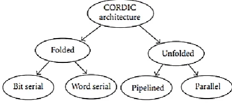
In general, the architectures can be broadly classified as folded and unfolded as shown in Figure 1, based upon the realization of the three iterative equations . Folded architectures are obtained by duplicating each of the difference equations of the CORDIC algorithm into hardware and time multiplexing all the iterations into a single functional unit. Folding provides a means for trading area for time in signal processing architectures. The folded architectures can be categorized into bit-serial and word-serial architectures depending on whether the functional unit implements the logic for one bit or one word of each iteration of the CORDIC algorithm. The CORDIC algorithm has traditionally been implemented using bit serial architecture with all iterations executed in the same hardware [3]. This slows down the computational device and hence, is not suitable for high speed implementation. The word serial architecture [7, 48] is an iterative CORDIC architecture obtained by realizing the iteration equations. In this architecture, the shifters are modified in each iteration to cause the desired shift for the iteration. The appropriate elementary angles are accessed from a lookup table. The most dominating speed factors during the iterations of word serial architecture are carry/borrow propagate addition/subtraction and variable shifting operations, rendering the conventional CORDIC [7] implementation slow for high speed applications. These drawbacks were overcome by unfolding the iteration process [1], so that each of the processing elements always perform the same iteration as shown in Figure 5.The main advantage of the unfolded pipelined architecture compared to folded architecture is high throughput due to the hard- wired shifts rather than time and area consuming barrel shifters and elimination of ROM. It may be noted that the pipelined architecture offers throughput improvement by a factor of n for n-bit precision at the expense of increasing the hardware by a factor less than n.
II.
BRIEF LITERATURE SURVEYCo-ordinate Rotation DIgital Computer is shortened as CORDIC. The simple principles of two-dimensional geometry are the basis of CORDIC arithmetic but the iterative method of a computational algorithm to implement this was first given by Jack E. Volder to compute multiplication, division and trigonometric functions in 1959[1], [2].
Concept, Design, and Implementation of Reconfigurable CORDIC Supriya Aggarwal, Pramod K. Meher, and Kavita Khare IEEE Transactions On Very Large Scale Integration (VLSI) Systems 2016.
The proposed method allow CORDIC to work in different modes and different trajectories of operations. A range of applications such as synchronizers, waveform generators, low-cost scientific calculators etc can use this reconfigurable CORDIC architectures , without affecting the maximum operating frequency. This proposed method save approximately 60% of the area compared to the conventional CORDIC architecture.
Implementation of a Fast Hybrid CORDIC Architecture Bhawna Tiwari, Nidhi Goel 2016 Second International Conference on Computational Intelligence & Communication Technology IEEE 2016. In this paper, the proposed architecture is faster in execution but reduced accuracy and high power consumption as compared to the reference architecture.
CORDIC-based FFT Real-time Processing Design and FPGA Implementation Aimei Tang*, Li Yu, Fangjian Han, Zhiqiang Zhang, 2016 IEEE 12th International Colloquium on Signal Processing & its Applications (CSPA2016), 4 - 6 March 2016, Melaka, Malaysia.
dual-port RAM, butterflies of the radix-2Decimation-In-Time (DIT) algorithm have been used to increase the performance of the design and Signal Noise Ratio is also increased as per the simulation results.
CORDIC II: A New Improved CORDIC Algorithm Mario Garrido, Member, IEEE, Petter Källström, Martin Kumm and Oscar Gustafsson, Senior Member, IEEE Ieee Transactions On Circuits And Systems Part Ii: Express Briefs 2016.
A number of versions of CORDIC algorithm are proposed but no authors has given the substitution of CORDIC micro-rotation. So a new algorithm called CORDIC II is presented that uses minimum number of adders as compared with the other CORDIC algorithm as it uses new variety of rotators.
CORDIC Architectures: A Survey B. Lakshmi and A. S. Dhar, Hindawi Publishing Corporation VLSI Design Volume 2010, doi:10.1155/2010/79489
This paper proposes various classification and survey of CORDIC algorithm and also focussed on algorithm that pre compute the direction of rotations. Depending on the specific application such algorithms are used. Special focus and more stress have been given on higher radix and redundant algorithms.
III.
PROBLEM DEFINITIONRectangular to polar conversion is an important operation in ALU and DSP processors wireless communication, multimedia etc. The conversion requires hardware implementation of squaring, square root, adder, and arctangent circuits. This results in hardware complexity, large area requirement and high power consumption. There are different types of architecture of CORDIC algorithm and each architecture has its own merits and demerits. So various existing methods have been studied and compared. From all the architectures, pipeline
CORDIC algorithm is best suited to implement rectangular to polar conversion.
IV.
MOTIVATIONIf FPGAs are implemented using digital signal processing algorithm, then the algorithm uses a nontrivial (transcendental) algebraic function, like square, square root, adder, and arctangent. Taylor series can be used to approximate these functions. The problem is then reduced to a sequence of multiply and adds operations. But more efficient approach, based on the Coordinate Rotation Digital Computer (CORDIC) algorithm can also be considered. This algorithm uses simple add, subtract and shift operations, which reduces hardware complexity of the circuit. The throughput of the circuit can be increased by pipelined CORDIC. This results in small, cheap, fast in calculation and reconfigurable hardware.
V.
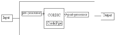
PROPOSED WORKFigure shows the block diagram of CORDIC processor. Three fundamental blocks of CORDIC Processor are the pre-processor, the post-processor and the actual CORDIC core.
Figure 2: Block Diagram of CORDIC processor
1. Pre-Processors and Post-Processors
places the CORDIC core’s results in the correct quadrant.
2. CORDIC
The actual CORDIC algorithm is performed by CORDIC Processor, therefore CORDIC core is considered as the heart of the CORDIC Processor Core. A pipeline of CordicPipe blocks are used to make the CORDIC and each CordicPipe block represents a single step in the iteration processes. For each iteration and the logic, the atan table is used. Pipelined structure is used to perform all the iterations. Pipelined structure makes CORDIC transformation in each clock cycle and enables to achieve highest throughput.
3. CORDIC Pipeline
A pipeline of CordicPipe blocks are used to make the CORDIC and the CordicPipe core performs each iteration step to manipulate the values as shown in the figure 3.
Figure 3: CORDIC Pipeline
VI.
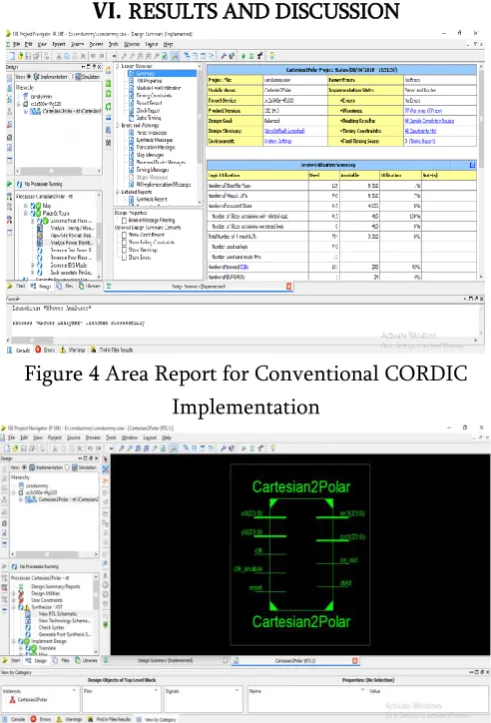
RESULTS AND DISCUSSIONFigure 4 Area Report for Conventional CORDIC Implementation
Figure 5 RTL Top view for Conventional CORDIC Implementation
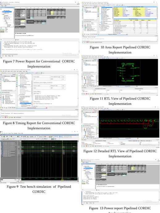
Figure 7 Power Report for Conventional CORDIC Implementation
Figure 8 Timing Report for Conventional CORDIC Implementation
Figure 9 Test bench simulation of Pipelined CORDIC
Figure 10 Area Report Pipelined CORDIC Implementation
Figure 11 RTL View of Pipelined CORDIC Implementation
Figure 12 Detailed RTL View of Pipelined CORDIC Implementation
Figure 14 Timing report of Pipelined CORDIC Implementation
Table I Comparative analysis of the conventional CORDIC and Pipelined CORDIC
Sr. No. Conventional CORDIC Reconfigurable Pipelined CORDIC 1 Number of slice
flip flops
129 1035
2 Number of 4
input LUTs
743 1016
3 Maximum
Frequency(MHz)
46.70 153.89
4 Power (mW) 0.81 0.81
Thus from the result obtained we observe that in conventional CORDIC area is optimized and in pipelined CORDIC speed is optimized
VII.
CONCLUSIONRectangular to polar conversion is an important operation in many applications, which uses complex hardware. So various existing methods have been studied, compared and better performance approach has been proposed. The block diagram of proposed work has been discussed, that uses simple add, subtract and shift operations. The CORDIC algorithm has been implemented in VHDL language and simulation has been carried on XILINX ISE software. We also conclude that in conventional CORDIC area
is optimized and in pipelined CORDIC speed is optimized.
VIII.
REFERENCES
[1].
J E. Volder, "The CORDIC trigonometric computing technique," IRE Trans. Electronic Computing, vol. EC-8, pp. 330-334, Sep. 1959.[2].
Sudhakar Reddy.P , Ramachandra Reddy "ASIC Implementation of Autocorrelation and CORDIC Algorithm for OFDM Based WLAN", ISSN 1450-216X Vol.27 No.4 (2009), pp.588-596[3].
C.-S. Wu, A.-Y. Wu, and C.-H. Lin, "A high-performance/low-latency vector rotational CORDIC architecture based on extended elementary angle set and trellis-based searching schemes," IEEE Trans. Circuits Syst. II, vol. 50, no. 9, pp. 589-601, Sep. 2003.[4].
R. Shukla and K. Ray, "Low latency hybrid CORDIC algorithm," IEEE Trans. Comput., vol. 63, no. 12, pp. 3066-3078, Dec 2014.[5].
C.-S. Wu and A.-Y. Wu, "Modified vector rotational CORDIC (MVR-CORDIC) algorithm and architecture," IEEE Trans. Circuits Syst. II, vol. 48, no. 6, pp. 548-561, Jun. 2001.[6].
S. Aggarwal, P. K. Meher, and K. Khare, "Area-time efficient scaling-free CORDIC using generalized micro-rotation selection," IEEE Trans. VLSI Syst., vol. 20, no. 8, pp. 1542-1546, Aug. 2012.[7].
F. Jaime, M. Snchez, J. Hormigo, J. Villalba, and E. Zapata, "Enhanced scaling-free CORDIC," IEEE Trans. Circuits Syst. I, vol. 57, no. 7, pp. 1654-1662, July 2010.[8].
Y. Liu, L. Fan, and T. Ma, "A modified CORDIC FPGA implementation for wave generation," Circuits Syst. Signal Process., vol. 33, no. 1, pp. 321-329, 2014.TRANSACTIONS ON VERY LARGE SCALE INTEGRATION (VLSI) SYSTEMS 2016.