© 2017 IJSRST | Volume 3 | Issue 1 | Print ISSN: 2395-6011 | Online ISSN: 2395-602X Themed Section: Scienceand Technology
A Novel Control for Reactive Power Compensation and Improve Power Factor
with Statcom Configuration
B. Prasanna Lakshmi
Ph.D Research Scholar, JNTUA University, Ananthapur , Andhra Pradesh, India
ABSTRACT
This paper deals with modelling of STATCOM along with the design of linear current and voltage controllers. The fuzzy logic control method is used to design linear current and voltage controllers to improve the power factor with the help of reactive power compensation. STATCOM is nothing but the static synchronous compensator which regulates the voltage and corrects the power factor at the point of common coupling by injecting reactive power. The principle of operation is same as that of synchronous condenser. The use of proposed method removes the fluctuations and improves the magnitude of the current and voltage also phase angle which goes to nearly zero value. The performance of the method is obtained through MATLAB SIMULINK tool box.
Keywords: Reactive Power Compensation, STATCOM, Fuzzy controller.
I.
INTRODUCTION
The STATCOM i.e. static compensator is very commonly used for the reactive power control. The STATCOM is also known as static VAR generator (SVG) is a voltage converterdevice which uses in order to generate the active and reactive power needed by the system. The STATCOM has several advantages such as fast response, continuous and quick control of reactive power. The power system becomes very complex because there is interconnection of long distance transmission lines [1-3]. The grids become unstable in nature as the loads are vary in their phase angle and magnitude that affects on power factor [4-6]. Commissioning new transmission systems was extremely expensive and also takes more amount of time to set up. Therefore, in order to meet increasing power demands, utilities must rely on power export or import arrangements through the existing transmission systems. To improve power factor the capacitor banks are used but it is having number of disadvantages [7].
non-linear controller [14]. The dynamic and steady state nature of STATCOM using SVPWM method (Space Vector Pulse Width Modulation) is more better than SPWM because SVPWM inverter has higher modulation index [15].
The linear controller method is more convenient for STATCOM application as compared to nonlinear controller [16-18]. In order to mitigate this, in [19] design of a linear current controller and voltage controller on the basis of gain and time constant adjustment along with the parameter of the coupling inductor and storage capacitor.
These controllers are used in STATCOM and control the reactive power for improvement of power factor on the variation of DC link voltage. But in this paper some fluctuations are there so that in order to avoid these fluctuations and to improves the reactive power we are introduced fuzzy controller for the improvement of power factor with reactive power compensation. In addition, this research work demonstrates fast, dynamic performance of the STATCOM in various operating conditions.
This paper is organized as follows. Section II illustrates the modelling of the STATCOM & analysis. Section III presents the design of fuzzy controller for the STATCOM. Section IV presents the simulation results. Finally, Section V concludes this paper.
II.
STATCOM MODELLING AND ANALYSIS
A. Operating principle:
As is well known, the STATCOM is, in principle, a static replacement of the age-old synchronous condenser. Fig.1 shows the schematic diagram of the STATCOM at PCC through coupling inductors. The fundamental phasor diagram of the STATCOM terminal voltage with the voltage at PCC for an inductive load in operation, neglecting the harmonic
in Figure 2. Ideally, increasing the amplitude of the STATCOM terminal voltage V~oa above the amplitude of the utility voltage V~sa causes leading current I~ca to be injected into the system at PCC as shown in Figure 2.
B. Modeling:
The modelling of the STATCOM, through well known, is viewed in the lines below, for the sake of convenience. The modelling is carried out with the following assumptions:
1. All switches are ideal.
2. The source voltages are balanced.
3. Rs represents the converter losses of the coupling inductor.
4. The harmonic contents caused by switching action are negligible.
Figure 1. Schematic diagram of STATCOM [19]
The 3-phase stationary abc co-ordinate vectors with 120 apart from each other are converted into αβ two-phase stationary coordinates. The α axis is aligned with a axis and leading β axis and both converted into dq two-phase rotating co-ordinates. The Park’s abc to dq transformation matrix is used here. The actual proposed circuit is too complex to analyze as a whole, so that it is partitioned into several basic sub-circuits, as shown in Figure 1. The 3-phase system voltage Vs,abc lagging with the phase angle α to the STATCOM output voltage Vo,abc and differential form of the STATCOM currents are defined in (1) and (2). = [ ] = √ [ ( ) ( )] (1)
( ) =- + - (2)
Where, , ̅, and have their usual connotations. The above voltages and currents are transformed into dq frame. ( ) = - - + - (3) - + - (4)
The switching function S of the STATCOM can be defined as follows:
S= [ ] = √ m
[ ( ) ( )] (5)
The modulation index, being constant for a programmed PWM, is given by,
MI=
= √ m
(6)
The STATCOM output voltages in dq transformation are
= m [ ]
(7)
The dc side current in the capacitor in dq transformation
= m [ ][ ] (8)
The voltage and current related in the dc side is given by,
= (9)
The complete mathematical model of the STATCOM in dq frame is obtained as,
[ ] = [ ] [ ] + [ ] (10)
III.
DESIGN OF FUZZY CONTROLLER FOR
STATCOM
A. Basics of Fuzzy controller
The basic diagram of fuzzy controller is shown in Figure 3.
Figue 3. Basic representation of fuzzy controller
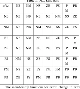
Table 1. FLC Rule Base
ε/∆ε NB NM NS ZE PS P
M PB
NB NB NB NB NB NM NS ZE
NM NB NB NM NM NS ZE PS
NS NB NM NS NS ZE PS P
M
ZE NB NM NS ZE PS P
M PB
PS NM NS ZE PS PS P
M PB
PM NS ZE PS PM PM PB PB
PB ZE PS PM PB PB PB PB
The membership functions for error, change in error and output is shown in Fig.4, 5 and 6 respectively.
Figure 4. Membership function of error(ε)
Figure 5. Membership function of change in error(∆ε)
Figure 6. Membership function of output
IV.
SIMULATION RESULTS
A. Simulation using FLC
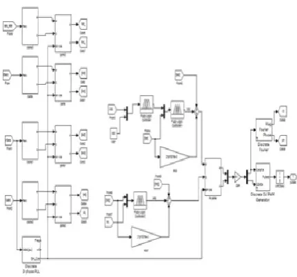
Figure 7. Proposed circuit configuration
Figure 8. Proposed control circuit using FLC
B. Responses using FLC Model
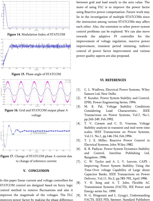
The dc link capacitor is charged to 550V at that time STATCOM operates well which is shown in Fig.9. In this paper fuzzy controller is used so that,it improves the magnitude of the voltages is shown in Fig.10,11, and 13. The controller output is connected to the voltage source converter, voltage gets increases that affects on the reactive and active power shown in Fig.12. The Fig.14 and 15 depicts modulation index of STATCOM which is unity and phase angle of the STATCOM is nearly zero respectively. The grid phase A and STATCOM output A voltage is shown in Fig.16.
The Figure 17 shows the change of STATCOM phase A current due to change of load current by an arrow.
Figure 9.Grid phase A voltage and phase A current
Figure 10. Grid phase A voltage and STATCOM phase A current
Figure 11. Active and reactive components of STATCOM current
Figure 12. Active and reactive power of STATCOM
Figure 14. Modulation Index of STATCOM
Figure 15. Phase angle of STATCOM
Figure 16. Grid and STATCOM output phase A voltage
Figure 17. Change of STATCOM phase A current due to change of reference current
V.
CONCLUSION
In this paper linear current and voltage controllers for STATCOM control are designed based on fuzzy logic control method to remove fluctuations and also it improves the magnitude of the voltages. The FLC improves power factor by making the phase difference
between grid and load nearly to the zero value. The moto of using FLC is to improve the power factor using Reactive power compensation. Future work may lie in the investigation of multiple STATCOMs since the interaction among various STATCOMs may affect each other. Also, the extension to other power system control problems can be explored. We can also move towards the adaptive PI controller for the improvement of voltage regulation, reactive power improvement, transient period imitating, indirect control of power factor improvement and various power quality aspects are also proposed.
VI.
REFERENCES
[1]. C. L. Wadhwa, Electrical Power Systems, Wiley Eastern Ltd, New Delhi.
[2]. P. Kundur, Power System Stability and Control, EPRI, Power Engineering Series, 1994.
[3]. M. K. Pal, Voltage Stability Conditions Considering Load Characteristic, IEEE Transactions on Power Systems, Vol.7, No.1, pp.243-249, Feb.1992.
[4]. T. V. Cutsem and C. D. Vournas, Voltage Stability analysis in transient and mid-term time scales, IEEE Transactions on Power Systems, Vol.11, No.1, pp.146-154, Feb.1994.
[5]. T. J. E. Miller, Reactive Power Control in Electrical Systems, John Wiley,1982.
[6]. K. R. Padiyar, Power System Dynamics-Stability and Control, Interline Publishing Ltd, Bangalore, 1996.
[7]. C. W. Taylor and A. L. V. Leuven, CAPS : Improving Power System Stability Using the Time-Over voltage Capability of Large shunt Capacitor Banks, IEEE Transactions on Power Delivery, Vol.11, No.2, pp.783-792, April 1996. [8]. Y. H. Song and A. T. John, Flexible AC
Transmission Systems (FACTS), IEE Power and Energy series Inc. 1999.
[10]. R. M. Mathur and R. K. Varma, Thyristor based FACTS Controllers for Electrical Transmission Systems, IEEE Power Engineering Society, Sponsorned, Wiley Interscience, 2002.
[11]. A. T. Johns, A. Ter-Gazarian and D. F. Wame, Flexible ac transmission systems (FACTS), IEE Power and Energy Series, London, U.K.
[12]. R. M. Mathur and R. K. Varma, Thyristors-based FACTS Controllers for Electrical Transmission Systems, IEEE Press, Wiley-Interscience Publication.
[13]. L. T. Moran, P. D. Ziogas and G. Joos, Analysis and Design of a Three- Phase Synchronous Solid-State Var Compansator, IEEE Trans. Industry Application, Vol. 25, No. 4, 1989, pp. 598-608.
[14]. C. Shauder and H. Mehta, Vector analysis and control of advanced static VAR compensators, IEE Proc, 140, No. 4, July 1993.
[15]. M. Sengupta, J. K. Moharana and A. Sengupta, Study on an Advanced Static VAR Compensator switched from a Space Vector PWM inverter-Analysis, simulation and comparison with the conventional sinusoidal PWM, NPEC 2003, IIT Bombay, 16-17 Oct 03 pp. 72-78.
[16]. D. M. Brod and D. W. Novotny, Current control of VSI - PWM inverter, IEEE Trans. Industrial Appl, Vol.IA-21, pp.562-570, July/Aug.1985. [17]. S. Buso, L. Malesani and P. Mattavelli,
Comparison of Current Control Techniques for Active Filter Application, IEEE Trans. Industrial Electronics, Vol.45, No.5, pp.722-729, October 1998.
[18]. S. K. Sethy and J. K. Moharana, Modeling, Design and Simulation of Current and Voltage Linear Controller of a STATCOM for Reactive Power Compensation, NSPEES-12, Sept.29-30, GIET, BBSR, pp. 37-44, 2012.
![Figure 1. Schematic diagram of STATCOM [19]](https://thumb-us.123doks.com/thumbv2/123dok_us/9087475.1443650/2.595.321.534.552.685/figure-schematic-diagram-of-statcom.webp)