DEVELOPMENT
OF
MESHLESS
METHOD
BOUNDARY
CONDITIONS FOR HIGH SPEED FLOWS
Krishna H.S1
1. SHOCK STRUCTURE MODEL
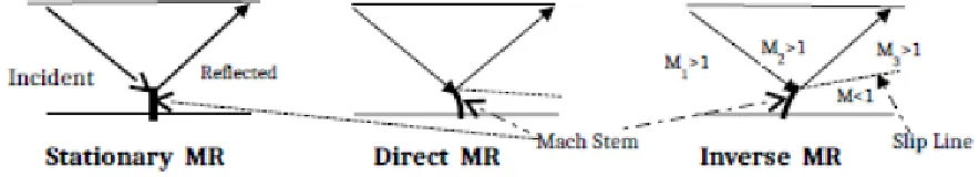
During numerical flow simulation, diffusion can be induced through artificial viscosity term to control development of flow. Early researchers included the dissipation term in the formulation of finite volume Euler equations to suppress odd-even point oscillations arising from pressure-velocity coupling. It was found that second difference diffusion terms with second and fourth difference pressure coefficients rendered wiggle-free computation. The highorder central differencing schemes produce accurate results in smooth flow regions but give rise to oscillations at shocks or discontinuities. This problem has been resolved through special upwinding methods and by Roe linearization technique [1], with or without characteristic decomposition. The development of Euler codes has paralleled the development of positivity or monotonicity preserving schemes that satisfy Jameson’s local extremum diminishing principle (LED criterion) [2] in order that physically meaningful values of pressure and density could be computed. Customarily, the residual is evaluated as convective and diffusive fluxes separately in order to improve the accuracy of computation of flow properties. If meshless technique is employed then the diffusive flux can be obtained as the product of point fluxes and least square (LSQ) coefficients along coordinate directions prior to time integration to steady state solution. Irregular boundaries and fine broken cells at the wall, which were constraints to computational accuracy of Cartesian mesh solvers, are now implemented efficiently by meshless wall boundary techniques [3]. The accuracy with which shock waves reflecting at the wall boundaries can be captured depends both on the computational schemes used and the shock structure model adopted. Even after a century old research, a concrete shock wave development model does not exist. Among various models suggested by researchers, the three-shock theory [4, 5] (3ST) putforth by von Neumann stands out as the most realistic one to describe the commonly encountered shock wave phenomena. In situations where only a regular shock reflection is expected as in ducted flows, a Mach wave reflection too may occur. A consequence of this effect is the appearance of Mach stem at the wall accompanied by a regular shock wave. Now, according to 3ST, non-regular shock reflection called Mach reflection (MR) is produced by three intersecting shock waves: incident wave, reflected wave and Mach stem. Their point of intersection called triple point (T) may move toward, away or parallel to the reflecting surface, giving rise to direct, inverse or stationary MR as shown in the Figures 1. These occurrences are termed as Mach stem and it forms the subject matter of this paper.
Figure 1 Different Types of Mach Reflection (MR) Occurring at the Wall
2. NEW WALL BOUNDARY CONDITIONS
The θ-β-M relationship [6] for oblique shock wave reflection is the basis for computing regular shock reflection. The schematics of regular oblique shock reflection between two reflecting surfaces are shown in the Figure 1. At the wall boundaries, the incident oblique shock wave Mach number, M1, is only slightly more than or just equal to the minimum Mach
1 Aeronautical Development Agency, PB 1718, Bangalore, India – 560017
International Journal of Latest Trends in Engineering and Technology
Vol.(9)Issue(1), pp.143-147
DOI: http://dx.doi.org/10.21172/1.91.22
e-ISSN:2278-621X
Abstract - Fully supersonic flows (Mach number =1 to 5) are characterized by diffusion phenomena and generation of shock waves. The vital role played by artificial viscosity in controlling diffusion is discussed here. A new set of wall boundary conditions are developed to eliminate undesirable Mach stem that occurs during regular reflection. Besides, a new two-step time marching scheme for gridless Cartesian Euler solvers is implemented to mitigate the need for flux splitting, entropy fixing or grid adaption while still employing simple techniques like state vector smoothing and scaling to capture shock waves crisply in a singular point flow computation.
number necessary for propagation of a straight, attached shock wave so that direct Mach reflection occurs as illustrated in Figure 1 instead of regular reflection of weak shock wave. The formation of local subsonic pockets of flow in the vicinity of the wall inside the boundary layer in real fluids may cause the reflected wave to be farther removed from the wall. The jump in static pressure rise across the reflected shock wave depicted in Figure 2 is cited as another reason for detachment from the boundary surface. In a ducted flow, the effect of pressure and velocity are contrary to each other, hence pressure rise at any point in the flow is accompanied by a corresponding decrease in velocity. At very high pressure and density prevailing in the duct, the expanding shock wave may cause localized subsonic pockets of flow to occur near the point of shock reflection and hence the appearance of Mach
Figure 2 Abrupt Pressure Rise across Shock Figure 3 Viscid and Inviscid Discontinuities
stem [7, 8]. Numerically, this abrupt pressure rise at reflection point O in Figure 2 can be controlled by stencil averaging [9,10] of density, ρ or Pressure,P and by ensuring local flow velocity, u in the streamwise direction to be fully supersonic so that only regular shock reflection occurs at the wall. It is obvious that special treatment of boundary conditions at the wall is essential for exact simulation of high speed flows. Additionally, if viscous and thermal diffusion effects are considered by using the Navier-Stokes equations then the inviscid discontinuities are transformed into smooth and continuously varying transitions instead of step-like transition as shown schematically in Figure 3. The transition distance Δ indicated in Figure 3 is about 0.1μm which requires extremely fine resolution mesh to capture internal shock structure.
The step by step procedure for eliminating Mach reflection is discussed below:
i) First and foremost step is to ensure proper connectivity between point clouds. By mixing the primitive variables of the current iteration with the previous one, smooth development of flow is ensured. In practice, this can be realized by using 3-point finite difference formula for state vector update of flow variable such as density of fluid, ρ, as a modified boundary condition:
(1)
Here, u, and v represent velocities along coordinate directions (i,j).
ii) Apart from the usual boundary conditions of surface tangency of flow (v.n=0) for inviscid flows, the standard 3- or 4-point formula normal to the wall is essential to compute the flow variables accurately at reflection points by augmenting the standard boundary conditions rather than merely applying the simple finite differencing scheme. The direct implementation of 4-point formula is not permissible because of steep pressure rise in the viscinity of the wall which may cause the solution to diverge. An implementation of combined 3- and 4-point formula at wall boundaries given below helps in computing the regular shock pressure P without Mach stem:
P3 = 0.5*(3*Pi,j+2–Pi,j+3) (2)
P4 = 0.125*(15*Pi,j+1 – 10*Pi,j+2 +3*Pi,j+3) (3)
Pi,j = Pi,j + (P3 ─ P4)
(4) iii) Finally, by either stencil averaging of density or pressure as in (eqn. 5) below or equivalently by applying successive relaxation scheme across the shock wave, adverse pressure gradients may be handled easily. Further, by applying time-dependent technique such as predictor-corrector method that permits mixed subsonic-supersonic flow computations [11] desirable smoothing may be achieved.
ρi,j = (λ÷2)*(ρi-1,j+ρi,j+1+ρi+1,j+ρi,j-1+ρi,j) ÷ 4 (5)
where diffusive constant, λ is assigned a value ranging from 0.8 to 0.9. In all the above cases, it is emphasized that these modified boundary conditions should be applied strictly at the wall boundaries to avoid distortion resulting from excessive smoothing of interior points.
3. TWO-STEP MESHLESS SCHEME
grid but an essential difference between the two exists in the distribution of neighbouring points. In meshless method, the nearest neighbours constitute the point cloud whereas in unstructured mesh, two successive points of computation need not be adjacent points. The connectivities between neighbouring points are determined by the directional derivatives or gradients of flux vector. A second order space discretization that stipulates C2 continuity between grid points forms the basis of the numerical scheme. Connectivity is destroyed if the points become collinear, which is surely a degenerate case that should be avoided. The popular edge-based meshless method described in literature [12] ensures reciprocity of nodes for proper connectivity and permit the use of approximate Riemann solvers for single midpoint flux computation. The fact that various Euler codes are based on different methods of computing fluxes makes accurate computation of convective fluxes all the more important in the development of flow solver. The procedure for modifying an existing grid-based Euler code to meshless [9-13] or hybrid code involves evaluating LSQ coefficients, aij and bij , along coordinate directions, finding the sum F (=af+bg) of spatial derivative of linearized convective fluxes f and g, and then integrating the discretised Euler equation to steady state solution by Runge-Kutta method. In order to ensure proper connectivity between point cloud stencils and to facilitate proper flow development, it is essential to smoothen the state vector at every node n as given below:
Step 1:
Step 2: (6)
Here, Q represents the smoothened state vector at node n, q is the current value of state vector, qˆ is its previous
iteration value, qt is the average value of the state vector of four triangular quadrants denoted as qI, qII, qIII and qIV [10] that make up 5-point stencil at point (i,j), ζ is a diffusion constant which is assigned a value of unity for highly diffusive flows such as expansion shock and a small fractional value (say 0.1) for all other flows and κ=10-5 introduces artificial compressibility into the solution to control expansion shock wave. More details about the two step scheme can be obtained from [9, 10] .
4. VALIDATION TEST CASES
As part of validation study, two standard tests are considered: i.) A low diffusion problem represented schematically by regular oblique shock wave at M=2.9 between two reflecting surfaces in Figure 4 and ii.) A high diffusion problem of expansion shock wave in a forward facing step at M=3. The codes employed for this purpose are 2-step, time marching, Cartesian meshless generic and CUSP Euler solvers described in [2, 14,15].
4.1. Regular Oblique Shock Reflection
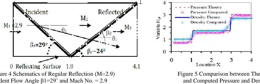
This test case establishes the efficacy of the Meshless solvers. The test set up for producing regular reflection must conform to the conditions [16] shown in Figure 4. The flow is rendered parallel to the wall by imposing condition (u,v,ρ,p)(x,1,t) = (2.61934,-0.50632,1.6999,1.5281) at the upper surface which in effect makes the flow to turn through deflection angle θ1= θ2 = 10.94º = tan-1(v/u). It is observed that there is close agreement between oblique shock theory and computed results [16,17] of generic Euler meshless code for pressure and density in the plane y=0.5 in Figure 5. Also, the regular oblique shock reflection for density computed by generic Euler code for 60x20 and 164x40 point cloud distributions illustrated in Figure 6 indicate exact simulation of incident and reflection angles as that occurring in an ideal regular reflection.
Figure 4 Schematics of Regular Reflection (M=2.9) Figure 5 Comparison between Theory
Figure 6 Regular Oblique Shock Reflection Using Generic Euler Code for 60x20 and 164x40 Point Cloud
4.2 Expansion Shock Wave
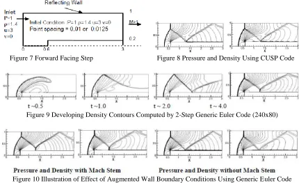
This test case demonstrates the capability of the code to produce highly accurate results for high speed diffusive flows. In Figure 7, the corner at the step of forward facing duct represents a singular point in the flow because it gives rise to expansion shock wave. All test cases discussed here are subject to the inlet, outlet and initial conditions shown in Figure 7 with uniform point cloud distribution of 240x80 points. The pressure and density contours obtained from CUSP scheme based Euler solver is presented in Figure 8. Besides this, the computations from generic Euler code showing the sequence of steps through which the flow evolves in the forward facing stepped duct between time t = 0.5 and t = 4 is presented in Figure 9. The new wall boundary conditions (eqn. 1 to 4) to eliminate Mach stem occurring in regular reflection has been implemented in a generic Euler code [15] and its results of nearly exact numerical simulation of flow phenomena as compared with that of Woodward and Collela grided Euler solver [18] is depicted in Figure 10.
Figure 7 Forward Facing Step Figure 8 Pressure and Density Using CUSP Code
Figure 9 Developing Density Contours Computed by 2-Step Generic Euler Code (240x80)
Figure 10 Illustration of Effect of Augmented Wall Boundary Conditions Using Generic Euler Code
5. CONCLUSION
successfully tackled by a new set of boundary conditions. The fact that complex flow simulation can be carried out without resorting to elaborate methods of clustering the mesh or splitting the fluxes to capture shocks accurately makes it a viable technique to implement in advanced CFD codes. While still speculative, meshless methods hold the promise of future seamless CFD code development.
6. REFERENCES
[1] A. Jameson, “Analysis and Design of Numerical Schemes for Gas Dynamics 2 Artificial Diffusion and Discrete Shock Structure”, International Journal of Computational Fluid Dynamics, Vol. 5, pp. 1–38, 1995.
[2] A. Jameson, “Analysis and Design of Numerical Schemes for Gas Dynamics 1 Artificial Diffusion, Upwind Biasing, Limiters and Their Effect on Accuracy and Multigrain convergence”, International J. of Computational Fluid Dynamics, Vol. 4, pp. 171– 218, 1995.
[3] D.J. Kirshman and F. Liu, “A gridless boundary condition method for the solution of Euler Equations on Embedded Cartesian Meshes with Multigrid”, J. of Computational Physics, pp.119-147, 2004.
[4] Ben-Dor G., Shock-wave Reflection phenomena, 12-17, Springer 2007.
[5] E.I. Vasilev, Toy Elperin and Gabi Ben-Dor, “Analytical Reconsideration of the von Neumann Paradox in the Reflection of a Shock Wave over a Wedge”, Physics of Fluids, 20, 046101, 2008.
[6] J..D..Anderson, Fundamentals of Aerodynamics, ISBN 0-07-100767-9, Mc-Graw Hill Int. Ed. , Chap. 9, 1991.6
[7] S. Jaisankar and S.V.Raghurama Rao, “A Central Rankine-Hugonoit Solver for Hyperbolic Conservation Laws”, J. of Computational Physics, pp. 781, 228, 2009.
[8] C. Praveen., Development and Application of Kinetic Meshless Methods for Euler Equations, PhD Thesis, IISc., India, July, 2004.
[9] H.S.Krishna, “A Two-Step Time Marching Technique for Classical CFD Codes”, 14th Annual Symposium of Aeronautical Society of India, Bangalore, CP-39, pp.120.Aug.10-11, 2012.
[10] H.S.Krishna, Diffusion Schemes Meshless Solvers for High Speed Internal Flows, Report No. ADA/LCA/ARD&P/085/2014, July 2014.
[11] D.D.Marshall and M.R.Stephen, “A New Inviscid Wall Boundary Condition Treatment for Embedded Boundary Cartesian Grid Schemes”, AIAA 2004-583, Reno, Nevada, 5-8 Jan. 2004.
[12] Aaron Katz and Antony Jameson, “A Comparison of Various Meshless Schemes within a Unified Algorithm”, Orlando, Florida, AIAA 2009-596, 2009. [13] E.P.C.Koh, H.M.Tsai and F. Liu, “Euler Solution Using Cartesian Grid with a Gridless Least-Squares Boundary Treatment”, AIAA Journal, Vol. 43,
No. 2, February 2005.
[14] S.M.Deshpande., “Kinetic Meshless Method in Computational Fluid Dynamics”, Symposium on Advances in Fluid Mechanics, NAL Bangalore, pp.13-31.2003.
[15] J.T.Batina, “A Gridless Euler / N-S Solver Algorithm for Complex Aircraft Application”, AIAA Paper 93- 0333, Jan. 1993.
[16] Hong Luo & J.D.Baum and R.Lohner , “A Hybrid Cartesian Grid and Gridless Method for Compressible Flows”, 43rd AIAA Aerospace Sciences Meeting and Exhibit, AIAA Paper 2005-0492, 1-16, 10-13, Jan 2005.
[17] Sukumar Chakravarthy, Development of Upwind Schemes for the Euler Equations, NASA CR 4043, pp.50, Jan. 1987.