Abstract— With the advancements of robotic technologies, the industrial environments are adopting more and more aspects of automation to enhance product quality and accuracy and to reduce product cost. One of these aspects is the use of Automated Guided Vehicle (AGV) which is gaining importance in industrial logistics and transportation systems.However, in case of developing countries like Bangladesh, the development and utilization of such sophisticated systems are not always cost effective. An initiative was taken to design and fabricate a group of low cost automated guided vehicles to perform logistics in a quasi - industrial environment. The group consisted of two robotic vehicles that were capable of carrying certain workpieces and supplying these to a predefined unloading location. These robots were microcontroller operated and were re-programmable to accommodate the possible changes those in real industrial environment. Test runs we re performed by programming these for maneuvering through both linear and curved trajectories. An imaginary industrial environment was prepared in the laboratory and the robots went through several successful test runs that validated the effectiveness of the prototypes. The research highlights the possibility of AGVs for the logistics purposes at reasonable cost using appropriate technology.
Index Term— industrial logistics, automated guided vehicles, appropriate technology.
I. INT RODUCT ION
AGV (Automated Guided Vehicle) robots are widely used to autonomously transport workpieces between various assembly stations by following special guidewires or colored strips. Some AGVs transport food and medication throughout hospitals by tracking the position ceiling lights, which are
M. Yakut Aliis a research assistant in the Department of Mechanical Engineering, University of South Carolina, Columbia, SC 29208, USA.
e-mail: [email protected]
S. G. M. Hossain is a research assistant in the Department of Mechanical Engineering, University of Nebraska Lincoln, Lincoln, NE
68503, USA
e-mail: [email protected]
H. Jamil is a research student in the Department of Mechanical Engineering, École Centrale de Nantes, France.
e-mail: [email protected]
M. Z. Haq is a professor in the Department of Mechanical Engineering, Bangladesh University of Engineering and T echnology,
Dhaka-1000, Bangladesh. Home page: http://teacher.buet.ac.bd/zahurul/index.html
e-mail: [email protected]
*T hese authors contributed equally to the work
manually specified beforehand to the robot. Some specialized robots take advantage of the regular geometric pattern of the office-spaces, supermarkets, warehouses, container terminals or even air-conditioning ducts [1-3]. In potentially dangerous and inhospitable environments, autonomous robots are gaining widespread popularity. Schulze and Zhao (2007) reported the widespread usage of AGVS in Europe and China [4]. For the developing countries, industrial application s of robots are not very popular and cheap labor cost plays an important role for such situation. However, when the production speed and accuracy are not to be sacrificed, application of automation employing robots offers a practical solution [5].
Although mobile robots have a broad set of applications, there is one fact that is true of virtually every successful mobile robot: its design involves the integration of many different bodies of knowledge and the design and construction of mobile robots is as much an art as a science [1]. Robots locomotion actuators, manipulators, control systems, sensor suits, efficient power supplies, well-engineered software – all of these subsystems have to be designed to fit together into an appropriate package suitable for carrying out robot’s task effectively, efficiently and safely [6].
To assess the possibility of design and fabrication of AGVs in Bangladesh - a developing country in South Asia, a group of robotic vehicles were developed and tested for effectiveness. In most stages of the prototype development, the application of appropriate technology and locally available raw materials and hardware components were considered to reduce the cost within permissible range for the local industries. The robots were made for picking up and delivering loads in predefined locations. The initial prototypes were designed to handle much lighter loads than most industrial applications. The loads pick up and delivery was planned such that there were interactions between the two AGVs. One of the robots (C-Bot) was capable of gripping a cylindrical load and delivering it to another robot (Tray-Bot). Tray-Bot's wheels rear were fixed to a single shaft so that it could follow a straight path whereas C-Bot had two rear wheels separately powered and controlled and the controller generated control actions based on the readings from optical encoders attached to the wheels. Baglivo et al. (2005) used such encoders on the driver wheels of their AGVs [7]. Both the robots included tactile sensors – for Tray-Bot these were provided to sense the unloading destination – for C-Bot these were used as a safety in case of a collision with Tray-Bot. The linear trajectory of Tray-Bot and the curved trajectory of C-Bot were achieved by repeated test runs on the test field and updating the controller
Development of Automated Guided Vehicles for
Industrial Logistics Applications in Developing
Countries Using Appropriate Technology
actions based on experimental restults . The AGVs showed promising results in fulfilling their requirements.
II. DUMMY INDUST RIAL SET UP
In the industries, numerous components of various sizes and shapes need to be transferred from place to place during the manufacturing process. Flexibility is always incorporated in the design of AGVs to meet such requirements of the industry. In this research, the robots were capable of handling cylindrical polystyrene blocks of 300 mm diameter. The operation of the interactions of the robots were based on an imaginary industrial environment where one of the robots picks up a block from a predefined loading place and supplies it to the another robot after maneuvering in a certain trajectory. The second robot senses the delivery and travels in a linear path to perform final delivery of the block to unload it.
A typical AVGs and the dummy industrial setup schematic are illustrated in Fig.1. The robots could be pre-programmed according to the map of the working field. In the present study, the robot C-Bot would receive workpiece from the loading station, which can be a conveyor belt or forklift/ truck unloading zone. C-Bot would move along a straight and curved path and reach the boundary where the load transfer could take place. C-Bot transferred the load to Tray-Bot and retreat to its initial position. Tray-Bot would sense the workpiece being delivered and move along the straight arrows and perform final delivery to the unloading station and retreat.
Fig. 1. T he laboratory dummy industrial environment setup schematic.
III. DESIGN MET HODOLOGY
The mechanical structures of the robots were prepared mostly using aluminum to reduce overall weight and subsequently reduced power requirement to drive it. Locally available hardware components and materials were employed in the design and fabrication of the robots.
A. Design considerations of C-Bot
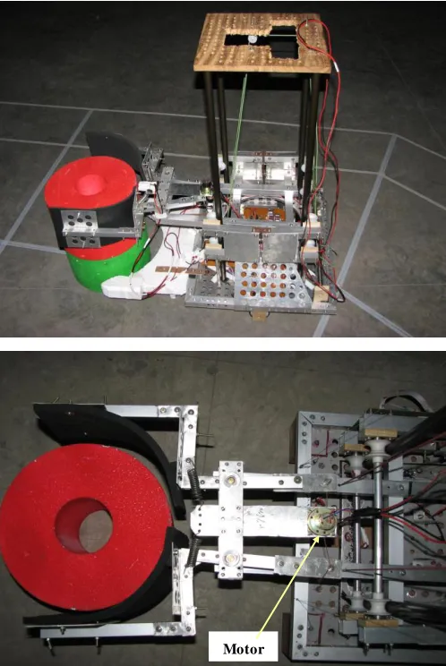
C-Bot, as shown in Fig. 2, was designed to maneuver in a linear/curved trajectory and was equipped with a gripper to grab the workpiece from the loading station and release it to
motors were used for both gripping and for the vertical movement of the gripper along four circular guide-ways. The vehicle had a dual motor drive system where both the motors were coupled directly to the wheels. A safety bumper was provided at the front portion of the vehicle to detect any obstacle that might come in front of its way.
Fig. 2. C-Bot (top) and the gripper (bottom).
B. Design considerations of Tray-Bot
Tray-Bot was operated in a straight path and so it had only one motor that was connected to the rear wheels by means of chain-sprockets. Its four wheels were adjusted carefully so that it could maintain the straight trajectory without noticeable deviation. The upper deck of the robot had a swinging tray made of aluminum. This portion contained two string-pulley mechanisms – one on the chassis to facilitate the rotation of the tray while the other one incorporated in the tray mechanism to perform a pulling operation which could finally push the cylindrical block (the workpiece) out of the tray and drop in the unloading station (Fig. 3).
Fig. 3. T ray-Bot and its tray.
IV. DRIVE AND CONT ROL SYST EM
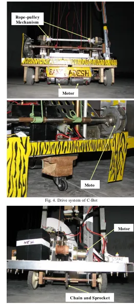
The C-Bot was designed as a three wheeler robot with two independently controllable wheels at the front and a free un-powered caster at the back (Fig. 4). Such a configuration provided very convenient forward and backward locomotion, as well as steering in any direction just by controlling the speeds and directions of the motors. The caster at the rear provided stabile pivoting for turning. The Tray-Bot drive motors were connected by chains to the drive shaft that accommodated two rear wheels, which ensured straight motion (Fig. 5).
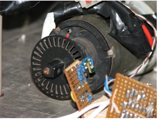
Both of the robots were controlled by PIC® 18F452 micro-controller based system, as shown in Fig. 6, using feedback signal from numerous sensors. Microcontroller generated Pulse Width Modulation (PWM) signals were utilized to control the drive motor’s speeds. Two PWM signals were used to control the speeds of two drive motors of C-Bot. Optical encoders , as shown in Fig. 7, were attached to the drive motors of the robots to provide the rotational speeds of the motors to the controller.
Fig. 4. Drive system of C-Bot
Fig. 5. Drive system of T ray-Bot.
Moto r Motor Powe r
Supply Motor
Rope -pulle y Me chanism
C hain and Sprocke t
Fig. 6. Control system electronics.
Fig. 7. Optical encoder connected to the motor shaft.
In the present study, although identical motors were driven from the same power source, it was found that the robot’s left wheel motor was slightly faster than the right wheel motor. Hence, experiments were carried out to find optimum duty cycle for the left motor to provide similar speed characteristics of the right motor. Tactile sensors were used in several places of both the robots and for their safety against pos sible collisions, the motion planning was performed in such a way that the robots would retard while being near to the destinations. Usage of visual sensor or camera was avoided as it may make the entire feedback system too complicated and raise the cost. This approach is similar to Lecking et al. (2005) who used laser scanner approaches instead of camera based systems to remain independent of luminance conditions that can be highly variable in industrial environments [8].
V. USE OF APPROPRIAT E TECHNOLOGY IN FABRICAT ION As the perspective of the whole research process was based on a developing country, it was not always possible to
part searches in local markets were performed and the initial design was changed accordingly to accommodate available resources. This happened for several components which exposed the reality of working situations.
Some examples of using appropriate technolog y has been illustrated in Figs. 2-7. In Tray-Bot, the pulling mechanism was made of belts collected from surplus store and pulleys from local hardware store (Fig. 5). Wooden structures were used to work as housing of tactile sensors. All the machining operations of the aluminum structures were performed in the local facility. In C-Bot, high torque motor was required to pull the whole gripper structure. Power window motors were used in this case which was collected from the automobile surplus store. Strings and wires were also local products which helped to keep the cost low. For the pulling mechanism to rotate Tray -Bot's tray, the housing of bearing and the pulley was made from wood whereas, the motor and chain-sprocket couples were collected from shipyard surplus stores.
All the circuit boards were made in the laboratory for price consideration (Fig. 6). Most of the electronic components (other than the micro-controllers) were local products. Even the optical encoders' circuits (Fig. 7) were prepared in the laboratory and all these components were working fairly well.
VI. TEST RUN RESULT S
The robots were tested in the dummy industrial facility prepared in the laboratory after the fabrication process and assembly. The first approach was to run the vehicles individually and observe their responses to the environment. Wheels were adjusted and the couplings and bearings were set to correct alignment as they were showing deviations after the very first few test runs. The individual sensors were tested for their accuracy and corrected wherever required.
The drive electronics went through some load tests where the vehicles were loaded and the corresponding current flow through the motors were measured. This was done to incorporate the electronic safety actions in the circuits.
Finally, the robots went through several full test runs where the C-Bot could successfully pick the workpiece and following the defined path, delivered it to Tray -Bot. Tray-Bot could successfully sense the workpiece placement on its tray by means of its tactile sensors and followed the assigned path to perform final delivery of the workpiece to the unloading station. The process was repeated several times to refine it to an acceptable level. At the end, it was proved to be a dependable and repeatable AGV system.
VII. CONCLUSION
case of mass production of s uch systems, some of the necessary key components could be imported. In this case, the cost of the components could be minimized by the large number of supply.
The robots developed in this research were lightweight and in some cases, slow speed. These could be modified and improved easily to meet the industry demands. From the test runs, it can be recommended that the usage of tactile sensors should be replaced by proximity sensors whenever possible as these sensors have lower expected life. Finally, it is worthwhile to mention that the possibility of AGVs development has a bright future in Bangladesh and the industries should come forward instead of becoming too much dependent on expected technology.
ACKNOWLEDGEMENT S
The authors would like to acknowledge the support of different laboratories of Bangladesh University of Engineering and Technology where the research works were performed.
REFERENCES
[1] R. Siegwart and I. R. Nourbakhsh, Introduction to Autonom ous
Mobile Robots. MIT Press, Cambridge, MA, USA, 2004.
[2] I. F. A. Vis, “ Survey of Research in the Design and Control of Automated Guided Vehicle Systems,” European Journal of
Operational Research, Vol. 170, pp. 677-709, 2006.
[3] C. Cariou, R. Lenain, B. T huilot and M. Berducat, "Automatic Guidance of a Four-Wheel-Steering Mobile Robot for Accurate Field Operations," Journal of Field Robotics, Vol. 26, pp.504– 518, 2009.
[4] L. Schulze, S. Behling, and S. Buhrs, “ Automated Guided Vehicle Systems: a Driver for Increased Business Performance”, in Proc. International Multi Conference of Engineers and Com puter
Scientists 2008, Volum e II, IMECS 2008, Hong Kong, 2008.
[5] L. Schulze and L. Zhao, “ Worldwide Development and Application of Automated Guided Vehicle Systems,” International
Journal of Services Operations and Inform atics, Vol. 2, pp. 164 –
176, 2007.
[6] J. L. Jones, A. M. Flynn and B. A. Seiger, Mobile Robots:
Inspiration to Im plem entation, AK Peters, Ltd.,1998.
[7] L. Baglivo, M. D. Cecco, F. Angrilli, F. T ecchio and A. Pivato, “An Integrated Hardware/ Software Platform for Both Simulation and Real-T ime Autonomous Guided Vehicles Navigation”, in Proc.
Of the 19th European Conference on Modeling and Sim ulation,
2005.
[8] D. Lecking, O. Wulf and B. Wagner, “ Variable Pallet Pick-Up for Automatic Guided Vehicles in Industrial Environments,” Logistics
Fair CeMAT, Hannover, 2005.
M. Yakut Ali received his B.S. in Mechanical Engineering from Bangladesh University of Engineering and T echnology, Dhaka, Bangladesh in 2007 with emphasis on Robotics and Mechatronics. He is currently working as a research assistant in Mechanical Engineering Department, University of South Carolina, Columbia, SC 29208 USA and working towards his M.S. degree in Mechanical Engineering. He is conducting both theoretical and experimental research on microfluidics and nanofluidics and micro and nano scale heat transfer.
S.G.M. Hossain received his B.S. in Mechanical Engineering from Bangladesh University of Engineering and T echnology, Dhaka, Bangladesh in 2007 with emphasis on Robotics and Mechatronics. He is currently working as a research assistant in Mechanical Engineering Department, University of Nebraska, Lincoln, NE USA and working towards his M.S. degree in Mechanical Engineering. He is conducting both theoretical and experimental research on Bio-mechanics and Bio-materials. His research interests include Bio-robotics.
H. Jamil received B.S. in Mechanical Engineering from Bangladesh University of Engineering and T echnology, Dhaka, Bangladesh in 2007 with emphasis on Robotics and Mechatronics. He is currently working towards his M.S. in Computational Mechanics at École Centrale de Nantes, France.