e-ISSN: 2278-067X, p-ISSN: 2278-800X, www.ijerd.com
Volume 12, Issue
6
(
June
2016), PP.27-32
Implementation of Variable Hysteresis Band Current Control
Technique for Three Phase PWM Rectifier Under Unbalanced
Input Impedance Condition.
Shailendra R.Teli
1, Shrikant S. Mopari
21
P.G. Student, Government College Of Engineering, Aurangabad, India
2Assistant Professor, Government College Of Engineering, Aurangabad, India
Abstract:-
This paper presents a closed loop control strategy to eliminated harmonics present at input and output side of rectifier when rectifier operate under unbalance input impedance condition. The unbalance present at input side of rectifier cause even harmonic at DC output side and odd harmonic in the input current as well as it affect the cost of DC side capacitor and AC side filter. To improve the performance of PWM rectifier, variable hysteresis current control technique has been implemented. Hysteresis current controller of variable bandwidth is used to track line current of all the three phases independently.Keywords:-
Harmonics, Pulse width modulation (PWM) rectifier, Unbalanced input condition, Hysteresis controller..I.
INTRODUCTION
Recent years the PWM rectifier has been widely used because it offers the possibility of low distortion line current with nearly unity power factor at any load condition [1]. It has advantages like instantaneous reversal of power flow, controllability of DC link voltage. PWM rectifier has wide application such as in uninterruptible power supply (UPS) system, for front end converter, renewable energy system, medium voltage (MV) high power application and also in regenerative low voltage (LV). However for given application stated above PWM rectifier is designed under consideration of balanced input condition. Unfortunately the benefits stated above are not fully realized under unbalanced input condition [2]. Unbalanced input condition can occur for a variety of reason such as non-uniformly distributed single phase load, faults, weak input supply or unsymmetrical nature transformer windings. These unbalance condition cause imbalance in the three phase supply both in magnitude as well as in phase angle.
The unbalance input voltage or impedance will be source of abnormal second harmonic at DC bus which reflect back to input causing flow of third order harmonics current. Thus the third order harmonic current causes a fourth order harmonic voltage on the DC bus and so on. This results in appearance of even harmonic at the DC output and odd harmonic in the input current. This cause adverse effect on system and make system unstable [3].Unbalance input condition are responsible for producing many problems in the operation of static converters like signal interference, relay malfunctioning, over voltage and excessive current as a result of resonance due to harmonic voltage or current in the network. The excessive losses in terms of heat in rotating machine and error in induction type KWH meter [4].
Since European EN50160 standards allows 6% low order supply voltage harmonic and supply voltage sag/swells within ±10%. Normal performance of PWM rectifier should be ensured under such varying and unbalanced supply voltage condition. Two approach are feasible to eliminate the harmonics appearing at the output DC link voltage and line side current. One approach is to use bulk filter to remove the ripple in the output voltage and input current. However it would slow down the dynamic response of the PWM boost rectifier. The other alternative is to use active control scheme to minimize the harmonics so that small size input/output filters can be used. This will also improve dynamic response of the PWM rectifier.
This paper presents variable hysteresis current control technique to reduce harmonic present at input and output side of rectifier under unbalance input impedances. Whether ever unbalance input impedances present high quality of input currents and output DC voltage are obtained. Here variable bandwidth of hysteresis current controller is used to track line current of all the three phases independently.
II.
LITERATURE REVIEW
A. Feed-forward control method
not operate under extreme unbalance condition. With respect to above approach A.V.Stankovic et al [6] proposed a method for PWM boost type rectifier under unbalance input voltage as well as unbalance input impedance. The proposed technique clears problem of adjustable power factor under input unbalanced operating condition. A.V.Stankovic et al [7] has proposed technique for complete harmonic elimination of PWM boost type rectifier at unity power factor under extreme unbalanced condition. The main advantage of that proposed method, PWM boost type rectifier can operate from the single phase supply in case where three phase source is not available.
B. Repetitive control scheme
Shinji Hara et al. [9] implemented a repetitive controller for three phase PWM rectifier in continuous time domain. To compensate all high frequency components in periodic reference input or disturbances by continuous time repetitive controller an unrealistic requirement for a proper controlled plant must be improved to assure stability. This requirement of controller overcome by Masayoshi et al.[10] by designing repetitive controller in discrete time domain. Discrete time domain limits the highest frequency components. It has an application in disk-file actuator system. X. H. WU et al. [11] design a repetitive controller in frequency domain for three phase PWM rectifier for DC link voltage and supply side current harmonics under unbalanced operating conditions. The main advantage of designing RC in frequency domain is the simplicity in control algorithm and real time implementation. The controller design would be easier in frequency domain than in time domain. Frequency domain repetitive controller enhances the robustness of the control system.
C. Vienna Rectifier
Traditionally three phase diode rectifier and thyristor rectifier are widely used in common AC-DC power conversion and rectifier-inverter based AC motor drives however such topology draw pulsed current from AC mains, causing low input power factor (PF)and large current harmonics pollution into utilities, resulting in increased distortion of supply voltage and losses contributing to inefficient use of electrical energy. In recent year various controlled technique has been proposed in order to reduce the voltage stress on power switches. The rectifier with variable switching frequency controller results in heavy interaction between phases when midpoint of DC link capacitor is not connected to the ground or source neutral of controlled rectifier. This results in acoustic noise, high switching losses and difficulty in designing input filter. C. Qiao. et al. [12] proposed constant frequency integration controller for three phase star connected switch three level rectifier (VIENNA) with continue conduction mode at unity power factor correction. The proposed controller can operate by sensing either inductor current or switching current. The operation of VIENNA rectifier at constant switching frequency not only reduce the harmonics at DC side of rectifier but also the voltage stress on power switch devices over two level converter. However when the neutral point potential operation imbalance, the capacitor voltage exceed half of DC link voltage which increase the voltage stress of power devices. LiGao He et al. [13] proposed a neutral point potential balancing controller for three level three switch VIENNA rectifier base on balance factor correction by measurement of input phase current. The proposed method balance neutral point potential with small variation by generating duty cycle of PWM signal with the help of real time calculation. June-Seok Lee et al. [14] introduced carrier based discrete PWM for VIENNA rectifier. The proposed method has high efficiency compare to carrier based continuous PWM method.
D. Hysteresis controller
study of different types of hysteresis controller namely constant hysteresis band, sinusoidal hysteresis band, adaptive hysteresis band and simplified adaptive hysteresis band for input current control.
III.
THEORETICAL APPROACH
The PWM rectifier is shown in Fig.(1). It is assumed that input voltage is balanced but input impedance is unbalanced. Harmonic elimination can be achieved by generating unbalanced command for three input currents under unbalanced input impedances [7].
Fig.1: PWM rectifier
Where,
V1,V2,V3 : Input voltages for three phases I1,I2,I3 : Input currents for three phases Z1,Z2,Z3 : Input impedances for three phases VS1,VS2,VS3 : Synthesized voltages
SW1,SW2,SW3 : Switching function for three phases V1
* ,V2
* ,V3
* : Conjugate of input voltages for three phases
S,S* : Apparent power and conjugate of apparent power
Vdc : DC output voltage
Three phase input voltages are,
1 1 1 1 Z I VS V (1)
2 2 2 2 Z I VS V (2)
3 3 3 3 Z I VS V (3)
Synthesized voltage can be expressed as,
2 2 1 1
dc S
V SW
V (4)
2 2 2 2
dc S
V SW
V (5)
2 2 3 3
dc S
V SW
V (6)
By substituting (4)-(6) into (1)-(3). The (7)-(9) equations are obtained,
2 2 1 1 1 1
dc V SW I Z
V (7)
2 2 2 2 2
2 dc
V SW I Z
V (8)
2 2 3 3 3 3
dc V SW I Z
V (9)
0
3 2 1I I
I (10)
Complex of apparent power is,
3 * 3 2 * 2 1 * 1
* V I V I V I
By multiplying equations (7), (8), (9) by I1,I2, I3 respectively and adding them up following equation is obtained, )
( 2
2 1 1 2 2 3 3 2 3 3 2 2 2 2 1 1 3 3 2 2 1
1 SW I SW I SW I
V I Z I Z I Z I V I V I
V dc (12)
0 3 3 2 2 1
1I SW I SWI
SW (13)
from equation (12) and (13),
2 3 3 2 2 2 2 1 1 3 3 2 2 1
1I V I V I Z I Z I Z I
V (14)
Equation (13) represented the condition for second order harmonics elimination. Equation (10), (11) and (13) represent a set of three equations with three unknowns. After solving these equations for three phase line current 𝐼1, 𝐼2and 𝐼3with all parameters known such as input complex power S, input voltages 𝑉1, 𝑉2and 𝑉3, input impedances 𝑍1, 𝑍2and 𝑍3 result in quadratic equation in terms of𝐼3. The correct value is select based on phase sequence of solution.
0 ) ( ) ( ) ( ) ( ) ( ) )( ( 2 ) ( 2 ) )( ( ) ( ) ( ) ( ) )( ( ) ( 2 2 * 1 * 2 * 2 1 * 1 * 2 1 2 * 3 2 * 1 * 2 * 1 * 3 2 1 * * 1 * 2 * 1 1 2 * 1 * 3 1 3 2 3 3 1 2 * 1 * 2 2 * 1 * 3 2 1 * 1 * 2 * 1 * 3 1 2 V V S Z Z V V V V S I V V V V Z Z S V V S Z V V V V V V I Z Z V V V V Z Z V V V V Z (15)
The phase current I2 can be obtained using equation (15). There are,
) ( ) ( * 1 * 2 * 1 * 3 3 * 2 V V V V I S I (16)
Equation (10) is used to calculate 𝐼1.These line currents from Equations (10), (15) and (16) are used as reference currents for harmonic elimination under unbalanced input impedances.
IV.
CONTROL METHOD
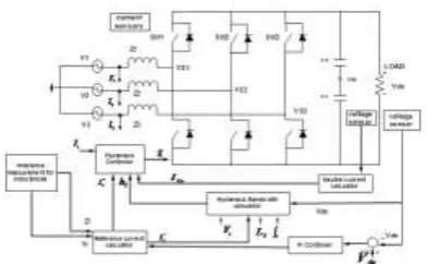
Schematic diagram for implementation of three phase PWM rectifier for unbalanced input impedance condition is shown in fig(2).The PWM rectifier is operated at near constant switching frequency method. The input-output harmonic elimination method is used to calculate the magnitude and phase angle of the reference currents. There are three input sinusoidal voltage sources representing a three phase input supply. Three input inductors connected with the three phases represent the input impedances. There are six IGBTs connected with anti-parallel diode representing the bidirectional switches of the PWM three phase rectifier. The rectifier output is given to two identical series-connected DC link capacitors. The voltage at midpoint of the two capacitors with respect to AC side neutral point is used to calculate neutral current. Here the current controller is a hysteresis controller with variable bandwidth and is used to track line current of all the three phases independently. Measured value of three phase currents (Ia,Ib,Ic), calculated neutral current IO, and hysteresis bandwidth (h), are inputs to the controller as shown in Fig.2 The output of the controller gives gate signals to all six IGBTs of the converter module. Equation (17) presents instantaneous value of the bandwidth of hysteresis controller h required to keep the switching frequency constant at a pre-set value fs [8].
Fig.2: Schematic diagram for implementation of three phase PWM rectifier for unbalanced input impedance condition.
The hysteresis bandwidth h varies in time and is periodic in nature. The frequency of hysteresis bandwidth plot is twice as that of fundamental frequency and is cosine in nature as it is shifted by 90 degree from the fundamental component. The bandwidth h depends on the values of output dc voltage, source instantaneous value of voltage, source input inductance, reference current and frequency of operation set.
V.
SIMULATION RESULTS
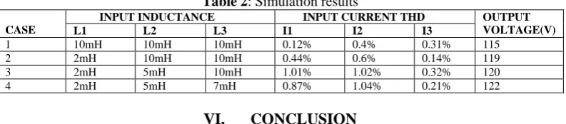
The unbalance at source side of rectifier is done by unbalancing source impedances. There are four simulation results shown of supply AC current and DC output voltage for balance and unbalance condition. Parameter used in simulation is shown in table 1. Input current THD, input inductance and output voltage at different cases are shown in table 2.
Table 1.Parameter used in simulation Sr. No Input L inductances Fundamental
frequency
Input supply voltage Output resistive load
L1 L2 L3 V1 V2 V3
1. 10mH 10mH 10mH 50Hz 60∟0 60∟-120 60∟120 150𝛺
Simulation results of case1 shows balance condition. At second case one phase is unbalance by placing one phase inductance value other than 10mH here 2mH is taken. Same applied for case 3 and case 4.
Fig3:case1output DC voltage and input AC current at balance condition
Fig5:case3 output DC voltage and input AC current at two phase unbalance condition.
Fig6: case4 output DC voltage and input AC current at three phase unbalance condition.
Table 2: Simulation results
CASE
INPUT INDUCTANCE INPUT CURRENT THD OUTPUT VOLTAGE(V)
L1 L2 L3 I1 I2 I3
1 10mH 10mH 10mH 0.12% 0.4% 0.31% 115
2 2mH 10mH 10mH 0.44% 0.6% 0.14% 119
3 2mH 5mH 10mH 1.01% 1.02% 0.32% 120
4 2mH 5mH 7mH 0.87% 1.04% 0.21% 122
VI.
CONCLUSION
This paper presents the implementation of sinusoidal variable hysteresis band current controller for three phase PWM rectifier operating at constant switching frequency 9 kHz with unity power factor. The closed loop technique is used to adjust the DC link voltage and elimination of input harmonics by updating reference current through feedback loop. The calculation of bandwidth for grounded midpoint DC link capacitor is then extended to floating condition using neutral current addition in current controller. This method reduce the harmonic contain in source current to lowest value and voltage controller is used to produce the reference current proportional to input power needed to maintain DC link voltage constant. The simulation results shows that the controller not only exhibits excellent adaptability, input harmonic reduction for unbalance input condition but also providing high reliability and simple controller at unity power factor.
REFERENCES
[1]. J.W.Wilson, “The Forced-Commutated Inverter As a Regenrative Rectifier,” IEEE transaction on industrial Applications, VOL IA-21, no. 4,pp. 769-775, Nov/Dec. 1984.
[2]. L.Moran, P.D.Ziogas, and G.Joos, “Design Aspects of Synchronous PWM Rectifier-Inverter System Under Unbalanced Input Voltage Conditions,” IEEE transaction on industrial Applications, VOL 28, no. 6,pp. 1286-1293, Nov/Dec. 1992.
[3]. R.P. stratford, D.E. Steeper, “Reaactive Compensation and Harmonic Supression for Industrial power Systems Using Thyristor Converters,” 1974 IAS Annual Meeting, 21 pp.
[4]. Joseph S. Subjak, , and John S. Mcquilkin, “Harmonics-Causes, Effects, Measurements, and Analysis: An Update” IEEE transaction on industrial applications, VOL 26, NO.6.November/December1990.
[5]. A.V.Stankovic, and T.A.Lipo, “A Novel Control Method for Input-Output Harmonic Elimination of the PWM Boost-Type Rectifier Under Simultaneous Unbalanced Operating Condition” 0-7803-5864-3/ 2000 IEEE.
[6]. A.V.Stankovic, and T.A.Lipo, “A Generalized Control Method for Input-Output Harmonic Elimination of the PWM Boost-Type Rectifier Under Simultaneous Unbalanced Input Voltage and Input Impedances” 0-7803-7067-8/ 2001 IEEE.
[7]. Ana VladanStankovic, and Kechen, “A New Control Method for Input-Output Harmonic Elimination of the PWM Boost-Type Rectifier Under Extreme Unbalanced Operating Conditions” IEEE transaction on industrial electronics, VOL 56, NO.7.july 2009. [8]. Upadhyay Abhishek Kumar, “A Generalized Control Method for Constant Switching Frequency Three Phase PWM Boost Rectifier
Under Extreme Unbalanced Operation Condition” (2015). ETD Archive. Paper 739.
[9]. Hara .S, OmataT.and Nakano M., “Synthesis of Repetetive control systems and its application” Proc. Of 24th CDC , Dec 1985 [10]. Masayoshi T, Tsao and K Chew, “Analysis and synthesis of discrete time repetitive controller” Trans, ASME: J dyn.
SystDevices,Vol 110, pp, 271-280, Jan 1988
[11]. X.H.Wu, S.K.Panda, and J.X.Xu, “ DC Link Voltage and Supply-Side Current Harmonics Minimization of Three Phase PWM Boost Rectifier Using Frequency Domain Based Repetitive current Controllers” 0885-8993/2008 IEEE.
[12]. C. Qiao and Keyue Ma Smedley, “Three phase unity power factor star connected switch (VIENNA) rectifier with unified constant frequency integration control” IEEE transaction on power electronics, VOL 18, NO.4.july 2003.
[13]. LiGao He and XinbingChen,“A neutral point potential balance control strategy based on vector controlled VIENNA rectifier” 978-1-4244-5287-3/2010 IEEE.
[14]. June- Seok Lee and Kyo-Beum Lee, “Performance analysis of carrier based discontinuous PWM method for VIENNA rectifier with neutral point voltage balance” IEEE transaction on power electronics, VOL 31, NO.6.june 2016.
[15]. J. W. Kolar and F. C. Zach, “A novel three-phase utility interface minimizing line current harmonics of high-power telecommunications rectifier modules,” in Proc. Telecommun. Energy Conf., 1994, pp. 367–374.
[16]. A. I. Maswood, A. K. Yusop, and M. A. Rahman, “A novel suppressed link rectifier-inverter topology with unity power factor,” IEEE Trans.Power Electron., vol. 17, no. 5, pp. 692–700, Sep. 2002.
[17]. Fangrui Liu and A. I. Maswood, “ A novel hysteresis band current control of Three Phase Three level unity PF rectifier with constant switching frequency” IEEE Trans.Power Electron., vol. 21, no. 6, Nov. 2006.