Evaluation of Steganographic Techniques
Based on Logic Gate and Shift Operators
Poonam yadav
M.Tech. Student, CSE Deptt., G.I.T.M., Gurgaon (Haryana)-India.
Rajesh kumar
Assit. Professor in CSE, G.I.T.M., Gurgaon (Haryana)-India.
Sonia gulati
Assit. Professor in CSE, G.I.T.M., Gurgaon (Haryana)-India.
Abstract— We are proposing evaluation of steganographic methods based on digital logic gates and shift operators. The modern secure image steganography presents a challenging task of transferring the embedded information to the destination without being detected. In this paper Logic Gate AND, OR, XOR, NOT and Shift Operators SHL, SHR, CIL, CIR are used on image matrix to derive the information matrix in this technique.The embedding can be reduced to large extent by using this technique.the logic gate and shift operator can be used combined.Then the address of row that derive the information matrix can be embedded into the along with the code of operator and Gates. This technique reduces large embedding We have used digital operations
based on logic gates and shift operators to derive the hidden information from image data. Keywords- Steganography, Hiding Information, Digital Logic,.
I.INTRODUCTION
Steganography is name given to techniques used for hiding information in digital objects such as image, video or sound files etc. Hiding information [4]in digital images open wide spectrum of applications such as – Secure communication, copy- right protection, and data authentication.
People use cryptography to send secret messages to one another without a third party overseeing the message. Steganography is a type of cryptography in which the secret message is hidden in a digital picture. The basic structure of Steganography is made up of three components: the “carrier”, the message, and the key. The carrier can be a painting, a digital image, an mp3, even a TCP/IP packet among other things. It is the object that will ‘carry’ the hidden message. A key is used to decode/decipher/discover the hidden message. This can be anything from a password, a pattern, a black-light, or even lemon juice. Steganography is the process of hiding a secret message within a larger one in such a way that someone cannot know the presence or contents of the hidden message. Although related, Steganography is not to be confused with encryption, which is the process of making
a message unintelligible—Steganography attempts to hide the existence of communication. Stegnography technique is classified as -
• Text-based Steganography - in which the message to be sent is embedded in a text file by formatting it based on line-shift coding, word-shift coding, feature coding etc. Reformatting of the text destroys the embedded content hence the technique is not robust.
• Audio Steganography - alters audio files so that they contain hidden messages. The techniques are LSB manipulation, phase coding and echo hiding.
• Image Steganography - hides message in the images. This technique is the most
Application of Steganography
• Copyright Protection
• Feature Tagging • Secret Communications
• Characterizing Data Hiding Techniques
• Perceptual Transparency
• Steganography in Image
II.STEGNOGRAPHY IN IMAGE
Information can be hide into images by using different technique.This complete chapter describe about the technique used for hiding the information into images
Classification of Stenographic Technique 1. Least significant bit insertion
2. Algorithms and transform 3. Masking and filtering
4. Logic Gates and Shift Operator Technique
Least significant bit insertion: In LSB Steganography, the least significantbits of the cover media’s digital data are used to conceal the message. The simplest of the LSB steganography techniques is LSB replacement. LSB replacement steganography flips the last bit of each of the data values to reflect the message that needs to be hidden. The advantage of LSB embedding is its simplicity and many technique use this method.LSB embedding also alows high perceptual transparency.However,there are many weaknesses when robustness,temper resistance and other security issues are considered.
Algorithms and transform:
Transform technique can offer superior robustness against lossy compression beacause they are designed to resistor exploit the method of popular lossy compression algorithm.An example of a transform based stegnographic system is the ”Jpeg-jsteg” software,which embeds the message by modulating DCT cofficient of the stego image based upon bits of the message and round of error during quantization.Transform based stegnography also typically offer increasedrobustness to scaling and rotation or cropping,depending on the invariant properties of a particular transform.
Masking and filtering:
Techniques that attempt to embed information only in perceptually insignificant manner,such as LSB embedded technique, are vulnerable to having the embedded data distorted or quantized by lossy image compression. The masking Properties of the human visual system allow perceptually significant embedding to be unnoticed by an observer under normal viewing conditions.”Masking” refers to the phenomenon where a signal can be imperceptible to an obsever in the presence of another signal (reffered to as an masker.) The masking properties are the reson why it is difficult for one to find a randomly placed needle in a haystack; the needle can be in plain view to an observer (not obscured by an object) yet the observer will have great difficulty lacating the needle.Masking (sometime reffer to image adaptive) system perform analysis of the image and use the information to determineappropriate region to place the message data.Masking system can also use the analysis to vary the strength (amplitude) of the embedded data based upon local image characterstics to maximize robustness.These systems are embed in either the spatial or transform domain.
Logic Gate and Shift Operator Technique:
Logic gates AND, OR, NOT and Shift operator SHL, SHR, CIL, CIR are used on image matrix to derive the information matrix inthis technique.The embedding can be reduced to large extent by using this technique.The address of row that derive the information matrix can be embedded into the along with the code for operator and Gates.
The information to be hidden and image file are read as row of bits matrices are equal.Three methods are used to derive out the information matrix rows.These method are as given below-
1. Logic Gate method 2. Shift Operator Mtehod 3. Combined Method 1. Logic Gate Method
Logic gates AND, OR, XOR, and NOT are used on image matrix to derive the information matrix in this method.
Insertion Method
Extraction Method
The extraction method is reasonably simple. From the agreed bit locations (both at the transmitting and receiving ends) in the image, the turbo-encoded message is extracted, which is decoded to get the Master Bit Pattern.
Shift Operator Method
Shift operators are generally used in serial transfer of data in digital systems. During the shift operations, if serial input transfers a bit into left most position, it is called shift left operation. If the serial input transfers a bit into right most position, operation is called shift right operation. The information transferred through serial input determines the type of shift. There are three types of shifts: logical, circular, and arithmetic. A logic shift is one that transfers 0 through the serial input. We will adopt the symbol SHL and SHR for logical shift-left and shift right operations. The circular shift (also known as rotate operation) circulates the input bits around the two ends without loss of information.
Combined Method
This method is combination of logic gate and shift operator method. In this scheme, we can use either logic gates or shift operators on image matrix to derive information matrix. Due to option of applying more operations on image matrix, there is more chance of selecting an image for embedding information.
III.ENHANCEDSTEGNOGRAPHICTECHNIQUEBASEDONDIGITAL
After applying the technique on more than 100 images it was observed that as the size of the row of information matrix goes beyond 10 bytes the selection of carrier image is very difficult as it is hard to derive out the information. In case if we are not able to derive out the information row it will be very difficult to send information of more than 10 bytes.This problem found in Technique Based on Digital Logic
Steganographic Technique Based on Digital Logic can be enhanced by three ways. 3.1By Dividing the Information Row
The technique can be enhanced by dividing the complete set of information in such a way that the size of each row not goes beyond 6-10 bytes accordingly. Suppose we want to send information of 100 bytes we must divide the information in 10 rows each having 10 bytes so that each information row can be derived out of two rows of images easily.In Logic Gate and Shift Operators Based Technique when we use information dividing method we will have to embed 180 bits(18 bits for every 10 bytes information) as compare to 800 bits( 8 bits for each of 100 bytes) in case of LSB(two least significant bit).
For example:
The information we have taken is ‘ i want to complete’ and the image on which we performed the operation is as shown in figure2 , ‘leena.bmp’. Applying the function on leena.bmp it was observed that first 5 character of information can be driven from the OR of 100th and 483rd rows next five from the OR of 97th and 346th rows next five from OR of 21st and 397th rows and the last five can be driven from OR of 40th and 338th rows.3.2 Using Mod Operation
By applying Mod operation on the values of pixels of image before applying any logical operation the values of pixels can keep in restricted range which is suitable in deriving out the information row. If the orginal values are not suitable in deriving out the information row the Mod operation can be used. Example by Using Mod Operation :The information we have taken for this example is ‘prevent’. The function image34 is not able to derive out this information if applied on image given in figure7. If the value of the pixels of figure4 restricted in between 97 and 123 the information can be derive out by applying OR operation on the rows 14 and 142. The same is the case if we take information ‘inderj’. It can not be derive out by function image34 but can be derive out successfully by function 36 given above by applying OR on 173 and 231.
3.3. Combining both Mod and the Information Dividing Method
Mod opertion can be applied on the value of pixels to restrict them into required range after that the information row is divided into parts to improve the efficiency of the method which make use of solution given above. Example of Combining both Mod and the information Dividing Method:
The information we have taken for this example is ‘I m coming on monday’.The function image37 is not able to derive out this information if applied on image give in figure 2.If the value of this pixel of figure 4 restricted in between 97 and 123 and the information is dividanded into piece of information can be derive out by applying OR operation on the row 8 and 222, 6 and 205, 8 and 15,23 and 33.
IV.IMPLEMENTATION OF TECHNIQUE
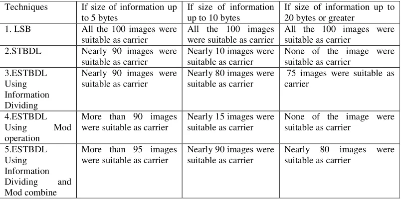
using Mod and dividing the information matrix into small parts. The result that were observed are shown in Table 1-3.Table 1 shows the number of image that can be selected as the carrier image out of 100 image
Techniques If size of information up to 5 bytes
If size of information up to 10 bytes
If size of information up to 20 bytes or greater
1. LSB All the 100 images were suitable as carrier
All the 100 images were suitable as carrier
All the 100 images were suitable as carrier
2.STBDL Nearly 90 images were suitable as carrier
Nearly 10 images were suitable as carrier
None of the image were suitable as carrier
3.ESTBDL Using
Information
Dividing Nearly 90 images were suitable as carrier
Nearly 80 images were suitable as carrier
75 images were suitable as carrier
4.ESTBDL Using Mod
operation More than 90 images were suitable as carrier
Nearly 15 images were suitable as carrier
None of the image were suitable as carrier
5.ESTBDL Using
Information Dividing and
Mod combine More than 95 images
were suitable as carrier
Nearly 90 images were suitable as carrier
Nearly 80 images were suitable as carrier
Table 2 shows the success rate of the three techniques in case of varying size of information.
Table 3 shows the maximum limit of information that can be transmitted via all the three techniques.The experiment was done on 512*512 bmp image of size 272 KB(2,62,144 bytes).In this table LSB, STBDL and ESTBDL are compared.The no of pixel in 512*512 images are 262144 and each pixel can store single bit so 262144 bits can be inserted.In ESTBDL 18 bits have to be insert for every 10 bytes so 10 bytes can be sent through 18 pixel (two bits in each pixel) so 1165084 bits can be sent through 262144 pixels.If size of information is more than 10 bytes it is difficult to derive out the information row so very difficult to send more than 160 bits.
Table 4 shows the no of bit to be embed in corresponds of varying size of information by using different techniques. Through the embedding of information is less when we divide the information into 10 bytes in comparison to 5 bytes. But the success rate of the later case is high. We also have to send two extra bits to tell the receiver about the size of row (5,10 bytes) and one for method used(whether using Mod or without Mod). Techniques If size of
information up to 10 bytes
If size of information up to 50 bytes
If size of information up to 100 bytes or greater
1.LSB 80 bits 400 bits 800 bits
Techniques If size of information up to 5 bytes
If size of information up to 10 bytes
If size of information up to 20 bytes or greater
1.LSB 100% 90% 100%
2.STBDL Nearly 90% 10% Nearly 0
3.ESTBDL More than 95%
90% 80%
Technique Maximum limit of embedding In image 512*512 of size
1.LSB 262144 bits
2.STBDL Very difficult to send more than 160 bits
2.ESTBDL if
information is divided into 5 bytes each row
38 bits 180 bits 360 bits
2.ESTBDL if
information is divided into 10 bytes each row
18 bits 90 bits 180 bits
Comparision between LSB and Technique Based on Digital Logic And Shift Operator shown in the figure below.
80 160
240 320
400
18 36 54
72 90 108
0 50 100 150 200 250 300 350 400 450
10 20 30 40 50 60
LSB
ESTBDL
Bytes to be sent
Data to be embed in both cases
B
it
s
to
b
e
e
m
b
e
d
The graph in figure shows the actual bits to be embedded in both LSB and Enhanced Stegnographic Techniques Based on Digital Logic(ESTBDL).
REFERENCES
[1] M Morris Mano, Computer System Architecture, 3rd
Edition,Printence Hall, 1998.
[2] Neil F. Johnson, Sushil Jajodia, “Exploring Steganography: Seeing the Unseen”, IEEE Computer, Feb 1998, pp 26-34.
[3] Neil F. Johnson, Sushil Jajodia, “Steganalysis of Images Created Using Current Steganography Software”, Lecture Notes in Computer Science,vol 1525, 1998, Springer-Verlag.
[4] JJ Eggers, R Bauml, Bernd Grid, “A Communication Approach to Image Steganography”, Proceedings of SPIE vol 4675, Jan 2002, Security and Watermarking of Multimedia Contents IV, San Jose, Callifornia.
[5] Parvinder Singh, Sudhir Batra, HR Sharma, “Evaluating the Performance of Message Hidden in 1st
and 2nd
Bit Plane”, WSEAS Transactions on Information Science and Applications, issue 8, vol 2, Aug 2005, pp 1220-1227.
[6] Parvinder Singh, Sudhir Batra HR Sharma, “Hiding Credentials in Biological Images”, A and B Research,Vol 22 no 1, Jan 2006, pp 22-25.
[7] SN Sivanandan, CK Gokulnath, K Prasanna, S Rajeev, “NFD Techniques for Efficient and Secured Information Hiding in Low Resolution Images”, Lecture Notes in Computer Sciences, vol 3347, Springer Verlag, 2004, pp 458-467.
[8] S Katzenbeisser, FAP Petitcolas, “Information Hiding Techniques for Steganography and Digital Watermarking”, Artech House, 2000. [9] NF Johnson, S Katzenbeisser, “A Survey of Steganographic Techniques”, Information Hiding, Artech House, pp 43-78, 2000. [10] R Chandramouli, Nasir Memmon, “Analysis of LSB based Image Steganography Techniques”, Proccedings of ICIP 2001, Greece, Oct
2001, pp 1019-1022.
[11] R Chanramouli, “A Mathematical Framework for Active Steganalysis”, ACM Multimedia Systems Journal, 2003.
[12] RJ Anderson, FAP Petitcolas, “On the Limits of Steganography”, IEEE Journal of Selected Areas in Communication, Special issue 16 no 4, 1998, pp 474-481.
[13] J Fridrich, MGoljan, R Du, “Reliable Detection of LSB Steganography in Grayscale and Color Images”, Proccedings of ACM Workshop on Multimedia and Security, Canada, Oct 200, pp 27-30.
[14] J Fridrich, MGoljan, R Du, “Detecting LSB Steganography in Color and Grayscale Images”, IEEE Multimedia, Nov 2001, pp 22-28. [15] MR Titchener, “Digital Encoding by Means of New T Codes to provide Improved Data Synchronization and Message Integrity”, IEE