Effect of Winglet Vortex Generators Orientation on
Heat Transfer Enhancement
Khudheyer S. Mushatet
Iltifat lazim edan
Mech. Eng. Dept. Mech. Eng. Dept.
College of Engineering College of Engineering
Thi-Qar University Thi-Qar University
E-mail:[email protected] E-mail: el _la [email protected]
Abstract-- experimental; and numerical investigation of three dimensional turbulent flow and heat transfer; inside a rectangular channel equipped with array of winglet vortex generators. Three pairs array of winglet vortex generators of different geometrical configuration as rectangular , triangular , semi circle and parabolic are considered. The array of winglet vortex generators is formed and distributed on the bottom hot surface with a facility for changing the angle of attack from (0° to 60°). ANSYS Fluent Code (15.0) based on a finite volume method is used to obtain the numerical results while a k- turbulence model is used to model the turbulent .The Reynolds number range is from 10000 to 50,000 under a constant heat flux boundary condition.. Two cases of winglet vortex generators array are included. The first case is anti stream common flow up. The second case is the combined anti and with stream common flow up. The two cases are tested for different values of angle of attack, the stream wise and span wise position between the vortex and Reynolds number. The obtained results show that the suggested arrangement of common ;flow up (anti and with stream) for vortex generator offers superior in heat transfer enhancement and overall thermal performance rated by 240% and 170% respectively. In addition, A signification increase in heat transfer enhancement , and overall thermal performance is found as the angle of attack and the positions between vortex generator increases .
Index Term— winglet vortex generators, turbulent channel flow, CFD
1. INTRODUCTION
The vortex generators are considered as a kind of passive heat transfer enhancement devices. This system is used for thermal equipment such as heat exchanger and internal cutting edge cooling of a gas turbine. The system of heat transfer enhancement is based on flow partition and reattachment. In general, flow reattachment introduces a strong shear flow on the surface behind each winglet or rib, resulting in an effective disturbance of the thermal boundary layer and in this way the heat transfer is improved [1]. A
effective in delaying boundary layer separation from the tube, reducing form drag,
transfer as it was observed with the wing could be avoided by using winglet- pair. The use of winglet-pair appeared to be a more attractive augmentation technique .Min et al. [19] developed a modified rectangular longitudinal vortex generator (LVG) obtain ned by cuting off the four corn ers of a rectangular wing. Their experimental results of this longitudinal mounted in rectangular channel proposed that the modified rectangular wing pairs of the modified rectangular wing pairs have better flow and heat transfer characteristics than those of rectangular wing pair. Zhang et al. [20] examined numerically the thermal enhancement and flow resistance characterristics in a rectangular channel with new makeup of double delta winglets and double delta winglet with holes. The double delta winglets with larger angle could make more effective heat transfer improvement. Caliskan [21] studied the heat transfer enhancement of punched LVGs using the infrared thermal image technique. He reported 23-55% increase in heat transfer performance and correlations for Nu were developed for corresponding LVGs.
In the work currently being done, a numerical and experimental study for three –dimensional turbulent flow and heat transfer in a channel with common flow up and combined anti and with stream wise common flow up arrangement of winglet vortex generator is performed. Three pairs array of winglet vortex generators of different
geometrical configuration as rectangular ,triangular ,semi-circle and parabolic are used. In addition a parabolic winglet type is tested as new suggested configuration under low and high Reynolds number rang (Re =103 to 5×10³).
Different values of stream wise distance which dimensionlized with channel height as Xr= 1.5,2 and 3 are
studied.
2. PROBLEM DESCRIPTION
The geometry consists of three dimensional rectangular channel with winglet vortex generators array. As shown in Fig. (1). Four types of winglet vortex generators as Triangular , Rectangular, Semi circle, and parabolic are tested. Different angles of attack(ß=0⁰,30⁰ ,45⁰ and 60⁰ )for vortex generators are studied.
The channel of length (L =1.08 m) ,height ( H =0.06m) and width(W =0.18m). Different sizes of vortex generators are considered while the ratio of area of the vortex generator with respect to the area of the channel inlet (Ar) is kept
constant. Three values of area ratio (Ar ) as
0.0740,0.0370,and 0.0231 are considered. Different values of stream wise distance which dimensionlized with channel height as Xr= 1.5,2 and 3 are tested. In addition ,the spine
wise dimensionless distance as Zr=1,1.5 is included. The distance from the channel inlet to the first pair of vortex generators is kept constant at (0.18) cm for the studied geometrical parameters.
Case 1.Anti stream wise common up.
Case 2. Combined anti and with stream wise common up.
Flow
x
z
Fig. 1. Schematic diagram of the physical problem.
3-EXPERIMENTAL WORK
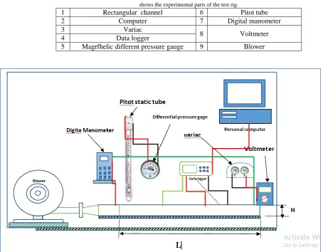
The schematic diagram of the test rig is depicted in
Fig.2.This system consisting of the rectangular channel is fabricated from galvanize steel material. The channel has a length (L=108 cm),height (H=6 cm) and width (w=18 cm)as shown in Fig.( 3).It consists of four walls, the two side walls are made of plexi glass to see clearly the vortex generators
and consequently ensuring that they are in their specified positions. The top and bottom walls are fabricated from galvanized steel.A heater of (3000)W is imposed to the bottom channel surface to generate a constant heat flux(q=1000W/m2). A glass wool insulation is used to
insulate the bottom hot surface in order to prevent the heat dissipation to the outside the channel .The experimental parts of the test rig is depicted in Fig.1.
Table I
shows the experimental parts of the test rig.
1 Rectangular channel 6 Pitot tube
2 Computer 7 Digital manometer
3 Variac
8 Voltmeter
4 Data logger
5 Magrfhelic different pressure gauge 9 Blower
Fig.2. schematic diagram of the test rig.
4.THE THEORETICAL WORK
9.The enfluence of thickness of vortex generators is assumed to be neglected.
The governing equation for the continuity ,momentum and energy based on the above assumptions are as follows.
∂u
∂x
+
∂v
∂y
+
∂w
∂z
= 0
(1)
X-Direction
(
∂u
2∂x
+
∂uv
∂y
+
∂uw
∂z
) = −
1
𝜌
∂P
∂x
+
∂
∂x
(
ʋ
∂u
∂x
) +
∂
∂y
(
ʋ
∂u
∂y
) +
∂
∂z
(
ʋ
∂u
∂z
)
+
∂
∂x
(−ú
̅̅̅) +
2∂
∂y
(−úv́
̅̅̅) +
∂
∂z
(−úẃ
̅̅̅̅)(2)
Y-Direction
(
∂vu
∂x
+
∂vv
∂y
+
∂vw
∂z
) = −
1
𝜌
∂P
∂y
+
∂
∂x
(
ʋ
∂v
∂x
) +
∂
∂y
(
ʋ
∂v
∂y
) +
∂
∂z
(
ʋ
∂v
∂z
)
+
∂
∂x
(−úv́
̅̅̅) +
∂
∂y
(−v́
̅̅̅) +
2∂
∂z
(−v́ẃ
̅̅̅̅) (3)
z-direction
(
∂wu
∂x
+
∂wv
∂y
+
∂w
2∂z
) = −
1
𝜌
∂P
∂z
+
∂
∂x
(
ʋ
∂w
∂x
) +
∂
∂y
(
ʋ
∂w
∂y
) +
∂
∂z
(
ʋ
∂w
∂z
)
+
∂
∂
x
(−
u
̅̅̅̅) +
́
w
́
∂
∂
y
(−
v
̅̅̅̅) +
́
w
́
∂
∂
z
(−
w
́
2
̅̅̅̅) (
4
)
4-1 Boundary Conditions
The boundary conditions are specified for each zone of the computational domain as follow:
At inlet:
Uniform inlet velocity ,U=Uin .
The flow is isothermal (T=Tin=300K).
At walls :
1- On the channel walls and vortex generators, the velocity is taken to be zero (no slip), u=v=w=0 . 2- A constant heat flux (q=1000W/m2) is imposed on the bottom surface.
3- 𝜕𝑝
𝜕𝑛 = 0 ,where n is a normal unit vector .
4- 𝑘 = 0 and = 0
At outlet :
1-A zero gage pressure is specified at the outlet domain.
5-NUMERICAL METHOD
A finite volume method is used to discretised the governing flow and heat equations. A Fluent code with Work bench is adopted to get the required results.
5.1 Grid independency
It is important to have a good fine mesh which must have a good distribution cells in order to have an accurate solution, for this reason, a grid independence study is made to choose the optimum grid to get a better solution. Table (2) shows the specified grid for all studied shapes. Grid independence tests are carried out in the following method before further numerical work. three sets of grid numbers, i.e.( 1244398, 1676622, 2543513 ) are adopted to examine the influence of the grid number on the calculation with vortex generators. grid number of 2543513 is applied in simulation to keep a moderate accuracy while saving computation time.
5-RESULTS AND DISCUSSION
The numerical results.
5.1 Validation with published results
A model validation must be performed to ensure that the present approach is reliable and applicable. This validation is done by comparing the results of the present model with results of anshuman and Singh.[22]as shown in Fig.(3). Acceptable agreement is obtained where the deviation does not exceeds 2% for Re=10000.
a-ß=30° b- ß=45°
0 0.5 1 1.5 2
0 10 20 30 40 50
Anshumanand Singh.[49]
0 0.5 1 1.5 2
X
0 10 20 30 40 50
S
p
a
n
w
is
e
N
ua
v
g
Present result
0 0.5 1 1.5 2
0 10 20 30 40 50
Anshuman and Singh[49]
0 0.5 1 1.5 2
X
0 10 20 30 40 50
S
p
a
n
e
w
is
e
N
ua
v
g
c- ß=60°
Fig. 3. Comparison of the present result with the published result of the Anshuman and Singh [22]
The discussion of numerical results are listed according to the studied cases as follows.
Case 1:anti stream wise common flow up
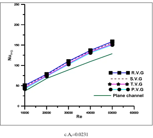
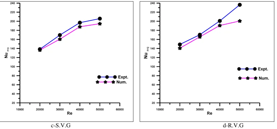
Fig. (4) shows the variation of average Nusselt number with Reynolds number for different shapes of vortex generators for ß=45° and Xr=1.5 . Generally ,it can be noted that the Nusselt number increases with the increasing Reynolds number because of the increasing the velocity which increases the heat transfer coefficient. It can be seen that, the rectangular vortex generators (R.V.G) provides a higher average Nusselt number than the semi-circle vortex generators (S.V.G), triangular vortex generators (T.V.G) and parabolic vortex generators (P.V.G) for all considered Reynolds number values. This behavior due to the sudden
expansion after the vortex generator. where of the RVG has the sharpest expansion with respect to the other shapes, which they have a gradual expansion. The sharpest expansion inducing the strongest longitudinal vortices and the higher flow obstruction, This configuration creates a stronger reverse flow as compared with those of other shapes, leading to better mixing between the core and the wall flows.
a.Ar=0.0740 b.Ar=0.0370
10000 20000 30000 40000 50000 60000 0
50 100 150 200 250
Plane channel
10000 20000 30000 40000 50000 60000 0
50 100 150 200 250
T.V.G
10000 20000 30000 40000 50000 60000 0
50 100 150 200 250
10000 20000 30000 40000 50000 60000 Re
0 50 100 150 200 250
N
ua
v
g
.
S.V.G
10000 20000 30000 40000 50000 60000 0
50 100 150 200 250
R.V.G
10000 20000 30000 40000 50000 60000 0
50 100 150 200 250
Plane channel
10000 20000 30000 40000 50000 60000 0
50 100 150 200 250
P.V.G
10000 20000 30000 40000 50000 60000 0
50 100 150 200 250
T.V.G
10000 20000 30000 40000 50000 60000 0
50 100 150 200 250
S.V.G
10000 20000 30000 40000 50000 60000 Re
0 50 100 150 200 250
N
ua
v
g
.
R.V.G
0 0.5 1 1.5 2
0 10 20 30 40 50
Present result
0 0.5 1 1.5 2
X
0 10 20 30 40 50
s
p
a
n
w
is
e
N
ua
v
g
c.Ar=0.0231
Fig. 4. Variation of average Nusselt number with Reynolds number for different shapes of vortex generators for ß=45° and Xr=1.5.
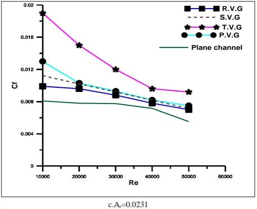
Fig.(5) shows the average skin friction coefficient distribution with Reynolds number for different shapes of vortex generators for ß=45° and Xr=1.5. Generally, it can be seen that the average
skin friction coefficient decrease with increasing Reynolds number. The friction factor enduced by using vortex generators is observed to be higher than that of the plane channel for all studied vortex generators shapes, This attributed to the suppression of the viscous sub-layer. This trend is increased as
vortex generators area ratio increases. The increased drag is always associated with extra pressure loss. When the area ratio increases ,the strength of longitudinal vortices are increases result in a reverse flow leading to noticeable increase in friction factor as compared with plane channel.
a.Ar=0.0740 b.Ar=0.0370
10000 20000 30000 40000 50000 60000 0.01
0.02 0.03
Plane channel
10000 20000 30000 40000 50000 60000 0.01
0.02 0.03
P.V.G
10000 20000 30000 40000 50000 60000 0.01
0.02 0.03
T.V.G
10000 20000 30000 40000 50000 60000 0.01
0.02
0.03 R.V.G
10000 20000 30000 40000 50000 60000
Re
0.01 0.02 0.03
C
f
S.V.G
10000 20000 30000 40000 50000 60000 0.01
0.02 0.03
Plane channel
10000 20000 30000 40000 50000 60000 0.01
0.02 0.03
P.V.G
10000 20000 30000 40000 50000 60000 0.01
0.02 0.03
T.V.G
10000 20000 30000 40000 50000 60000 0.01
0.02
0.03 R.V.G
10000 20000 30000 40000 50000 60000
Re
0.01 0.02 0.03
C
f
S.V.G
10000 20000 30000 40000 50000 60000 0
50 100 150 200 250
Plane channel
10000 20000 30000 40000 50000 60000 0
50 100 150 200 250
P.V.G
10000 20000 30000 40000 50000 60000 0
50 100 150 200 250
T.V.G
10000 20000 30000 40000 50000 60000 0
50 100 150 200 250
S.V.G
10000 20000 30000 40000 50000 60000
Re
0 50 100 150 200 250
N
uav
g
.
c.Ar=0.0231
Fig. 5. Variation of average skin friction factor with Reynolds number for different shapes of vortex generators for ß=45° and Xr=1.5
The fig.(6) shows the variation of average Nusselt number with Reynolds number for different angle of attack for Xr=1.5 and Ar=0.0370. This figure illustrates the maximum average Nusselt number were obtained at ß=45°,Re=50000. The
averaged Nusselt number of every shapes gradually increases with increasing Reynolds number. But, the R.V.Gwith ß=45° perform better in heat transfer. It is found that ß=0° gives minimum average Nusselt numberfollowed by 03°, 60°, 45° successively. This is because of the attack angle (ß ) that influences both the form and intensity of vortices. The R.V.G with smaller ß produce mainly longitudinal vortices which last over a long distance along the downstream direction. However, the smaller ß means smaller area facing the air flow, and the intensity of vortices generated is weaker. The R.V.G with larger ßcreate mainly transverse vortices which influence only the local area of R.V.G. Attack angle of ß=45°is of the optimum configuration for the best heat transfer performance in the present study. This trend is found for all tested shapes of vortex generators The optimum averaged Nusselt number is found for R.V.G. at Ar=0.0370, ß = 45° and Re = 50000. The optimum
increase in Nusselt number is( 31.6 % ) as compared with plane channel. The attack angle makes the vortex generators disturb the boundary layer more effectively and provide better air flow mix. and thus enhancing heat transfer.
a-T.V.G
b-P.V.G
10000 20000 30000 40000 50000 60000 0 20 40 60 80 100 120 140 160 180 200 ß=0
10000 20000 30000 40000 50000 60000 0 20 40 60 80 100 120 140 160 180 200 ß=30
10000 20000 30000 40000 50000 60000 0 20 40 60 80 100 120 140 160 180 200 ß=45
10000 20000 30000 40000 50000 60000 Re 0 20 40 60 80 100 120 140 160 180 200 N ua v g . ß=60
10000 20000 30000 40000 50000 60000 0 20 40 60 80 100 120 140 160 180 200 ß=0
10000 20000 30000 40000 50000 60000 0 20 40 60 80 100 120 140 160 180 200 ß=30
10000 20000 30000 40000 50000 60000 0 20 40 60 80 100 120 140 160 180 200 ß=60
10000 20000 30000 40000 50000 60000
Re 0 20 40 60 80 100 120 140 160 180 200 N
uav
g
.
ß=45
10000 20000 30000 40000 50000 60000 0 0.004 0.008 0.012 0.016 0.02 T.V.G
10000 20000 30000 40000 50000 60000 0 0.004 0.008 0.012 0.016 0.02 P.V.G
10000 20000 30000 40000 50000 60000 0 0.004 0.008 0.012 0.016 0.02 S.V.G
10000 20000 30000 40000 50000 60000 0 0.004 0.008 0.012 0.016 0.02 R.V.G
10000 20000 30000 40000 50000 60000
c-S.V.G
d-R.V.G
Fig. 6. Variation of average Nusselt number with Reynolds number for different effect angles of attack at the area ratio (0.0370)and Xr=1.5
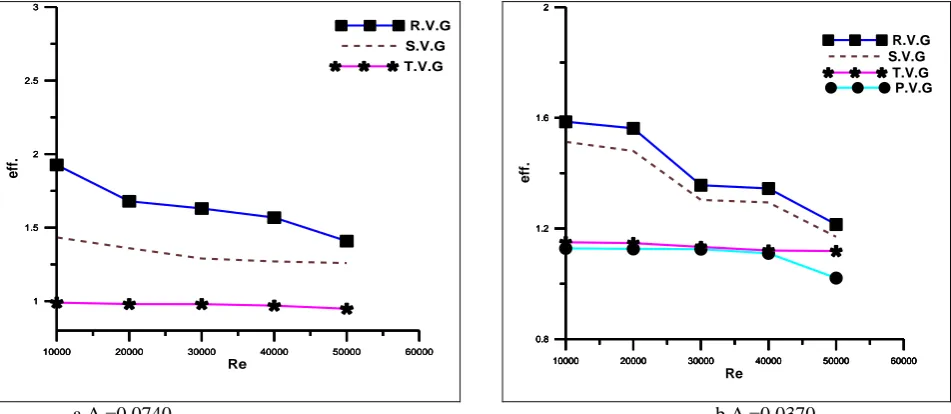
Fig.(7)shows the overall efficiency versus Reynolds numbers with different shapes and size of winglet vortex generators.It can be seen that the overall efficiency (η) are above unity for all the vortex generators. The enhancement factor tended to decrease with the rise in the Reynolds number values for all vortex generators. It is worth noting that the overall efficiency (η) of the R.V.G shape were higher than of those other shapes for all Reynolds number values. In addition , the minimum overall efficiency is noticed at the parabolic vortex generators. This indicated that the use of R.V.G leads to the advantage over that of P.V.G. where the maximum overall efficiency (η) is about 1.88 at Xr =1.5 and ß=45°.
a.Ar=0.0740 b.Ar=0.0370
10000 20000 30000 40000 50000 60000 0 40 80 120 160 200 ß=0
10000 20000 30000 40000 50000 60000 0 20 40 60 80 100 120 140 160 180 200 ß=30
10000 20000 30000 40000 50000 60000 0 20 40 60 80 100 120 140 160 180 200 ß=45
10000 20000 30000 40000 50000 60000
Re 0 20 40 60 80 100 120 140 160 180 200 N
uavg
.
ß=60
10000 20000 30000 40000 50000 60000 0 20 40 60 80 100 120 140 160 180 200 ß=0
10000 20000 30000 40000 50000 60000 0 20 40 60 80 100 120 140 160 180 200 ß=30
10000 20000 30000 40000 50000 60000 Re 0 20 40 60 80 100 120 140 160 180 200 N ua v g . ß=60
10000 20000 30000 40000 50000 60000 0 40 80 120 160 200 ß=45
10000 20000 30000 40000 50000 60000 1 1.5 2 2.5 3 T.V.G
10000 20000 30000 40000 50000 60000 1 1.5 2 2.5 3 S.V.G
10000 20000 30000 40000 50000 60000
Re 1 1.5 2 2.5 3 e ff . R.V.G
10000 20000 30000 40000 50000 60000 0.8
1.2 1.6 2
P.V.G
10000 20000 30000 40000 50000 60000 0.8
1.2 1.6 2
T.V.G
10000 20000 30000 40000 50000 60000 0.8
1.2 1.6 2
S.V.G
10000 20000 30000 40000 50000 60000
c.Ar=0.0231
Fig. 7. Variation of the overall efficiency with Reynolds number for different shapes of vortex generators for ß=45° and Xr=1.5
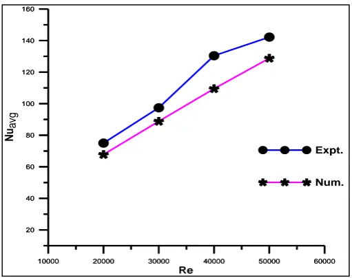
Fig. (8) shows the comparison between the experimental and numerical results of the plane channel.It can be illustrates that the numerical results agree well with the experimental results, with the mean deviation being about 11%. The agreement between the numerical and experimental results prove that the model and methods used in the present study are feasible and the numerical results are reliable.
Fig. 8. The comparison between the experimental and numerical results of the channel
Fig. (9) shows the comparison between numerical and experimental results of overall efficiency for the channel with T.V.G. This figure displays thatthe deviation percentage was about (5-6%) between the experimental and numerical results .This deviation value verifies that a good approach is followed for experimental and numerical work.
10000 20000 30000 40000 50000 60000 20
40 60 80 100 120 140 160
Num.
10000 20000 30000 40000 50000 60000 Re
20 40 60 80 100 120 140 160
N
uavg
Expt. 10000 20000 30000 40000 50000 60000 0.8
1 1.2 1.4
P.V.G
10000 20000 30000 40000 50000 60000 0.8
1 1.2 1.4
T.V.G
10000 20000 30000 40000 50000 60000 0.8
1 1.2 1.4
S.V.G
10000 20000 30000 40000 50000 60000 Re
0.8 1 1.2 1.4
e
ff
.
Fig. 9. Comp arison betwe en the overal
l efficie
ncy experi menta lly and numer
ically result s for many value of Reynolds number for T.V.G shape and Ar=0.0370, Xr=3.
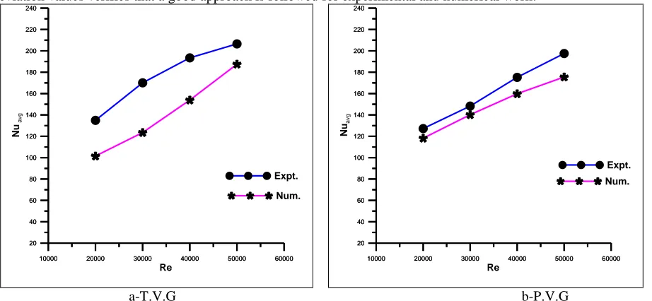
Fig.(10) shows the comparison between numerical and experimental results of average Nusselt number against Reynolds number for ß=45° and Ar=0.0370 and Xr=3. The deviation percentage for T.V.G was found to be about (7% ) between the
experimental and numerical result. while the R.V.G was about (4.7%),(4.4%)for S.V.G and P.V.G about (4.9%). These deviation values verifies that a good approach is followed for experimental and numerical work.
10000 20000 30000 40000 50000 60000 0.8
1.2 1.6 2
exp.ß=0
10000 20000 30000 40000 50000 60000
Re
0.8 1.2 1.6 2
e
ff
num.ß=0
10000 20000 30000 40000 50000 60000 0.8
1.2 1.6
2 num.ß=30
10000 20000 30000 40000 50000 60000
Re
0.8 1.2 1.6 2
e
ff
exp.ß=30
160 180 200 220 240
160 180 200 220 240
160 180 200 220 240
160 180 200 220 240 10000 20000 30000 40000 50000 60000
0.8 1.2 1.6 2
num.ß=60
10000 20000 30000 40000 50000 60000
Re
0.8 1.2 1.6 2
e
ff
exp.ß=60
10000 20000 30000 40000 50000 60000
Re
0.8 1.2 1.6 2
e
ff
num.ß=45
10000 20000 30000 40000 50000 60000
Re
0.8 1.2 1.6 2
c-S.V.G d-R.V.G
Fig. 10. Comparison between the average Nusselt number experimentally and numerically results for many value of Reynolds number for ß=45° and Ar=0.0370, Xr=3.
Case 2 Combine anti and with stream wise common flow up:
The variation of average Nusselt number with Reynolds number for different shapes of vortex generators for ß=45° and Xr=1.5 is shown in Fig. (11) . From this figure, it can be seen that the Nusselt number increases with the increasing
Reynolds number because of the increasing the velocity which increases the heat transfer coefficient. It can be seen that, the rectangular vortex generators (R.V.G) provides a higher average Nusselt number than the semi-circle vortex generators (S.V.G), triangular vortex generators (T.V.G) and parabolic vortex generators (P.V.G) for all considered Reynolds number values. This behavior due to the sudden expansion after the vortex generator. where of the RVG has the sharpest expansion with respect to the other shapes, which they have a gradual expansion. The sharpest expansion inducing the strongest longitudinal vorticesand the higher flow obstruction, This configuration creates a stronger reverse flow as compared with those of other shapes, leading to better mixing between the core and the wall flows. This trend is found for all tested sizes of vortex generators, however increasing the vortex generator size (represented here by Ar) leads to increase the average Nusselt
number. The optimum averaged Nusselt number is found for R.V.G. at Ar=0.0740, ß = 45° and Re = 50000. The optimum
increase in Nusselt number is 10% as compared with plane channel. Increasing the size of vortex leads to increase the flow restriction creating strong longitudinal vortices and thus enhancing heat transfer. The second case gives the higher than the first case about 17 % .
a-Ar=0.0740 b-Ar=0.0370 10000 20000 30000 40000 50000 60000
Re 20 40 60 80 100 120 140 160 180 200 220 240 N u a v g Expt.
10000 20000 30000 40000 50000 60000 20 40 60 80 100 120 140 160 180 200 220 240 Num.
10000 20000 30000 40000 50000 60000 20 40 60 80 100 120 140 160 180 200 220 240 Num.
10000 20000 30000 40000 50000 60000
Re 20 40 60 80 100 120 140 160 180 200 220 240 N u a v g Expt.
10000 20000 30000 40000 50000 60000 80 120 160 200 240 Plane
10000 20000 30000 40000 50000 60000 80 120 160 200 240 P.V.G
10000 20000 30000 40000 50000 60000 80 120 160 200 240 T.V.G
10000 20000 30000 40000 50000 60000 80 120 160 200 240 R.V.G
10000 20000 30000 40000 50000 60000
Re 80 120 160 200 240 N ua v g S.V.G
10000 20000 30000 40000 50000 60000 80 120 160 200 240 Plane
10000 20000 30000 40000 50000 60000 80 120 160 200 240 P.V.G
10000 20000 30000 40000 50000 60000 80 120 160 200 240 T.V.G
10000 20000 30000 40000 50000 60000 80 120 160 200 240 S.V.G
10000 20000 30000 40000 50000 60000
c-Ar=0.0231
Fig. 11. Variation of average Nusselt number with Reynolds number for different shapes of vortex generators for ß=45° and Xr=1.5
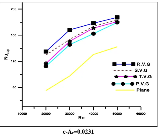
The variation of thermal enhancement ratio (Nuwith/Nuwithout) with Reynolds number for different angle of attack is
depicted in figure(12). It can be seen that the thermal enhancement ratio significantly increases with presence of vortex generators as compared with plane channel. This increase is noticed for any specified Reynolds number. For each vortex generator, it is decreased as Reynolds number increase . The introduction of VGs generates the longitudinal vortices and secondary flow, which breaks the boundary layer development. The boundary layer is thinner and the heat transfer is enhanced.As fact, the disturbing and mixing of flow would change the original field of flow and temperature and the flow separation point and the recirculation zone are delayed for the streamlined configuration. The higher area ratio of the winglet vortex generators greats more disturbance of the boundary layer and provides a better air flow mixing. Hence, the heat transfer is enhanced. The heat transfer enhancement from the rectangular vortex generator was significant more than those of other shapes vortex generators. The optimum increase is formed at an angle of attack (ß=45°). The thermal enhancement ratio varied from 1.6 to 2.8 with Re increasing. The reason of the above difference is described as follows. The winglet vortex generators make a hindrance in the main flow stream with a pressure difference in upstream and downstream of the vortex generators. This mechanism creates a strong longitudinal vortices. These vortices extend for a large distance behind the winglet vortex generators and vanish slowly in stream wise flow direction .This flow interaction accelerating the mixing process between the cold and hot fluid and thus increasing the thermal enhancement ratio. The optimum enhancement ratio is pointed at the rectangular vortex generators while the minimum at parabolic vortex generators. This trend is founded for all tested sizes of vortex generators, however increasing the vortex generator size (represented here by Ar) leads to increase the
thermal enhancement ratio. The optimum thermal enhancement ratio is founded for R.V.G. at Ar=0.0073, ß = 45° and Re =
50000. The second case gives the higher than the first case about 20 % .
10000 20000 30000 40000 50000 60000 80
120 160 200
Plane
10000 20000 30000 40000 50000 60000 80
120 160 200
P.V.G
10000 20000 30000 40000 50000 60000 80
120 160 200
T.V.G
10000 20000 30000 40000 50000 60000 80
120 160 200
S.V.G
10000 20000 30000 40000 50000 60000 Re
80 120 160 200
N
uavg
a-T.V.G b-S.V.G
c-R.V.G d-P.V.G
Fig. 12. Variation of the Nusselt number ratio Nwith/Nwithout(enhancement ratio) with Reynolds number for different angle of attack and Xr=1.5
The variation of average Nusselt number against Reynolds number due to the change in vortex generator angles of attack is depicted in Figure(13) for Ar =(0.0370) and Xr=1.5. Generally ,it can be observed that increasing the angle of attack leads to
increase the average Nusselt number as compared with plane channel. It is found the angle of attack affect the average Nusselt number variation ,where it increase as the angle of attack increase up to ß= 45° and them for all the considered vortex generators decreases. The Nusselt number at ß= 45° is marginally larger than that at ß= 60° Hence, the T.V.G gives the optimum Nusselt number at ß= 45°. The attack angle makes the T.V.G disturbs the boundary layer more effectively and provide better air flow mix.
The average Nusselt number of the channel with semi-circle vortex generators ( S.V.G ) is clearly increased in comparison with those of the plane channel. The Nusselt number at ß= 45° is marginally larger than that at ß= 60°and angle of attack ß=60 is greater than (ß=30°,0°). Hence, the ß=45° attack angle is the more optimal angle for the S.V.G. The second case gives the higher than the first case about 17 % .
10000 20000 30000 40000 50000 60000 0
0.4 0.8 1.2 1.6
2 Ar=0.0704
10000 20000 30000 40000 50000 60000 0 0.4 0.8 1.2 1.6 2
Ar=0.0370
10000 20000 30000 40000 50000 60000 Re 0 0.4 0.8 1.2 1.6 2 N
u w
it h / N uw it h o u t
Ar=0.0231
10000 20000 30000 40000 50000 60000 0 0.5 1 1.5 2 2.5 ß=0
10000 20000 30000 40000 50000 60000 0 0.5 1 1.5 2 2.5 ß=45
10000 20000 30000 40000 50000 60000 0 0.5 1 1.5 2 2.5 ß=60
10000 20000 30000 40000 50000 60000
Re 0 0.5 1 1.5 2 2.5 N uw it h / N uw it h o u t ß=30
10000 20000 30000 40000 50000 60000 0 0.2 0.4 0.6 0.8 1 1.2 1.4 1.6 1.8 2 2.2 2.4 ß=0
10000 20000 30000 40000 50000 60000 0 0.2 0.4 0.6 0.8 1 1.2 1.4 1.6 1.8 2 2.2 2.4 R e ß=30
10000 20000 30000 40000 50000 60000 0 0.2 0.4 0.6 0.8 1 1.2 1.4 1.6 1.8 2 2.2 2.4 N uw it h / N uw it h o u t ß=60
10000 20000 30000 40000 50000 60000 Re 0 0.2 0.4 0.6 0.8 1 1.2 1.4 1.6 1.8 2 2.2 2.4 ß=45
10000 20000 30000 40000 50000 60000 0
1 2 3
Ar=0.0370
10000 20000 30000 40000 50000 60000 Re 0 1 2 3 N u w it h / N
u w
it
h
o
u
t
a-T.V.G b-P.V.G
c-S.V.G d-R.V.G
Fig. 10. Variation of average Nusselt number with Reynolds number for different effect angles of attack at the area ratio (0.0370)and Xr=1.5
6-Conclusions
The potential using of winglet vortex generators array with different shapes, and arrangements in a three dimensional plane channel turbulent flow been conducted experimentally and numerically .The conclusions obtained from this
10000 20000 30000 40000 50000 60000 80
120 160 200 240
ß=0
10000 20000 30000 40000 50000 60000 80
120 160 200 240
ß=30
10000 20000 30000 40000 50000 60000 80
120 160 200 240
ß=45
10000 20000 30000 40000 50000 60000 Re
80 120 160 200 240
N
ua
v
g
ß=60
10000 20000 30000 40000 50000 60000 80
120 160 200 240
ß=0
10000 20000 30000 40000 50000 60000 80
120 160 200 240
ß=30
10000 20000 30000 40000 50000 60000 80
120 160 200 240
ß=45
10000 20000 30000 40000 50000 60000 Re
80 120 160 200 240
N
ua
v
g
ß=60
10000 20000 30000 40000 50000 60000
80 120 160 200 240
ß=0
10000 20000 30000 40000 50000 60000
80 120 160 200 240
ß=30
10000 20000 30000 40000 50000 60000
80 120 160 200 240
ß=45
10000 20000 30000 40000 50000 60000
Re 80
120 160 200 240
N
ua
v
g
ß=60
10000 20000 30000 40000 50000 60000 80
120 160 200 240
ß=0
10000 20000 30000 40000 50000 60000 80
120 160 200 240
ß=30
10000 20000 30000 40000 50000 60000 80
120 160 200 240
ß=60
10000 20000 30000 40000 50000 60000
Re
80 120 160 200 240
N
ua
v
g
5-Increasing the vortex generator angle of attack (ß), increase the thermal performance with considerable increase in pressure drop.
6- Enhancement of heat transfer for rectangular ,triangular ,semi circle and parabolic winglet vortex generators is enhanced by (146%-200%),(141%-71%),(144%-181%) and(134%-169%)respectively as compared with plane channel.
NOMENCLATURE
Symbol Definition SI
Units
Ach Channel area m2
Ar Area ratio
As Surface area m2
Av Vortex area m2
Cf Skin friction coefficient -
Cp Specific heat capacity J / kg.
K
CV Control volume -
Dh
Hydraulic diameter
(4A/Per.) m
f/fo Friction factor ratio
h Height of vortex m
H Channel height m
HD Dynamic head mm
k Thermal conductivity W/m.
K
L Channel length m
Nu Nusselt number -
Nuavg
Average Nusselt
number -
Nuwith/Nuwit hout
Thermal enhancement ratio
P Pressure Pa
PD The dynamic pressure Pa
q Heat Flux W/m2
Re Reynolds number -
T Temperature K
Symbol Definition SI
Units
Tb Bulk temperature K°
Tw Wall temperature K°
u Velocity in x-direction m/s
U Bulk inlet velocity m/s
v Velocity in y-direction m/s
W Channel width m
w Velocity in z-direction m/s
X1
The distance from the channel inlet to the first pair of vortex
generators
m
Xr Streamwise distance
y Transverse coordinate m
z Span wise coordinate m
REFERENCE
[1] S. Caliskan “Experimental investigation of heat transfer in a channel with new winglet-type vortex generators”, International Journal of Heat and
Mass Transfer 78 (2014) 604–614.
[2] M. Fiebig, P. Kallweit, N.K. Mitra, St. Tiggelbeck, Heat transfer enhancement and drag by longitudinal vortex generators in channel flow, Exp. Therm. Fluid Sci. 4 (1) (1991) 103e114.
[3] St. Tiggelbeck, N.K. Mitra, M. Fiebig, Experimental investigations of heat transfer enhancement and flow losses in a channel with double rows of longitudinal vortex generators, Int. J. Heat Mass Transf. 36 (9) (1993) 2327-2337.
[4] K. Torii, K.M. Kwak, K. Nishino, Heat transfer enhancement accompanying pressure-loss reduction with winglet-type vortex generators for fin-tube heat exchangers, Int. J. Heat Mass Transfer 45 (18) (2002) 3795–3801
[5] Jain A, Biswas G, Maurya D. Winglet-type vortex generators with common flow- up configu ration for fin-tube heat exchangers. Number Heat Transfer PartA 2003;43:201e19.
[6] A. Joardar, A.M. Jacobi, Heat transfer enhancement by winglet-type vortex generator arrays in compact plain-fin-and-tube heat exchangers, Int. J. Refrig. 31 (2008) 87-97.
[7] C. Liu, J.T. Teng, J.C. Chu, Y.L. Chiu, S.Y. Huang, S.P. Jin, T.T. Dang, R. Greif, H.H. Pan, Experimental investigations on liquid flow and heat transfer in rectangular microchannel with longitudinal vortex generators, Int. J. Heat Mass Transf. 54 (2011) 3069-3080.
[8] P. Promvonge, C. Khanoknaiyakarn, S. Kwankaomeng, C. Thianpong, Thermal behavior in solar air heater channel fitted with combined rib and deltawinglet, Int. Commun. Heat Mass Transf. 38 (2011) 749-756.
[9] M.C. Gentry, A.M. Jacobi, Heat transfer enhancement by delta –wing vortex generators on a flat plate: vortex interactions with the boundary layer, Exp. Therm. Fluid Sci. 14 (3) (1997) 231–242.
[10] M.C. Gentry, A.M. Jacobi, Heat tran sfer enhancement by delta–wing–generated tip vortices in flat–plate and developing channel flows, ASME J. Heat Transfer 124 (6) (2002) 1158–1168.
[11] T.M. Liou, C.C. Chen, T.W. Tsai, Heat transfer and fluid flow in a square duct with 12 different shaped vortex generators, ASME J. Heat Tran sfer 122 (2) (2000) 327–335.
[12] Du XZ, Feng LL, Li L, Yang L, Yang LY. Heat transfer enhancement of wavy finned flat tube by punched longitudinal vortex generators. Int J Heat Mass Transfer2014;75:368-80.
[13] C. Habchi, S. Russeil, D. Bougeard, J.L. Harion, T. Lemen and, D.D. Valle,H. Peerhossaini, Enhancing heat transfer in vortex generator-type multifunctional heat exchangers, Appl. Therm. Eng. 38 (2012) 14-25.
[14] J.M. Wu, W.Q. Tao, Numerical study on laminar convection heat transfer in a rectangular channel with longitudinal vortex generator. Part A: verification of field synergy principle, Int. J. Heat Mass Transf. 51 (2008) 1179-1191.
[15] G. Zhou, Q. Ye, Experimental investingations of thermal and flow characteristics of curved trapezoidal winglet type vortex generators, Appl. The rm. Eng. 37 (2012) 241–248.
[16] Q. Wang, Q. Chen, L. Wang, M. Zeng, Y. Huang, Z. Xiao, Experimental study of heat tran sfer enhancement in narrow rectangular chan nel with
longitudinal vortex generators, Nuclear Engineering Design 237 (2007) 686–693.
[17] G. Bisw as, P. Deb, S. Biswas, Generation of longitudinal streamwise vortices––a device for improveing heat exchanger design, Journal of Heat
Transfer 116 (1994) 588–597.
[18] G. Biswas, K. Torii, D. Fujii, K. Nishi no, Numerical and experimental determination of flow structure and heat transfer effects of longitudinal vortices in a channel flow, InternationalJournal of Heat and Mass Transfer 39 (16) (1996) 3441–3451.
[19] C.H. Min, C.Y. Qi, X.F. Kong, J.F. Dong, Expe rimental study of rectangular channel with modified rectangular longitudinal vortex generators, Int. J. Heat Mass Transf. 53 (15-16) (2010) 3023-3029.
[20] Zhang, T. Zhe Q. Huang, Xiao B. Zhang and Chun J. Liu," Numerical investigation of heat transfer using a novel punched vortex generator",International Journal of Computation and Methodology,2015, ISSN: 1040-7782 , pp. 1521-0634.
[21] Caliskan S. Experimental investigation of heat transfer in a channel with new winglet-type vortex generators. Int J Heat Mass Transf 2014;78:604-14.
![Fig. 3. Comparison of the present result with the published result of the Anshuman and Singh [22]](https://thumb-us.123doks.com/thumbv2/123dok_us/1352728.1643905/6.595.101.516.504.718/fig-comparison-present-result-published-result-anshuman-singh.webp)