(Full length research article)
Optimization of On-load Coil Parameters for High Frequency Industrial
Induction Heater
Pradip Kumar Sadhu
*
a, Nitai Palb and Atanu BandyopadhyaycaDepartment of Electrical Engineering, Indian School of Mines (Under MHRD, Govt. of India), Dhanbad-826004, Jharkhand, India, b
Department of Electrical Engineering, Indian School of Mines (Under MHRD, Govt. of India), Dhanbad-826004, Jharkhand, India
cDepartment of Electrical Engineering, Asansol Engineering College, Asansol-713304, West Bengal, India,
Received 19 April 2012; accepted 30 April 2012, Available online 1June 2012
Abstract
An exhaustive as well as comprehensive method for determining and optimizing the coil parameters for the best possible performance of high frequency resonant mirror inverter based induction heater is presented. Here litz wire is used for heating coil of the induction heater which controls the skin effect and proximity effect of conductor operating at high frequency. With the calculated optimum values of inductance and resistance at a particular operating frequency, HF mirror inverter topology has been simulated using P-SIM and MATLAB-SIMULINK. Afterwards waveforms have been shown. It is seen that at a particular switching frequency, the quality output is obtained, which can justify the feasibility for real implementation of high frequency mirror inverter fed induction heater in industrial appliances.
Keywords:
Induction heating, Mirror inverter, litz wire, P-SIM, MATLAB, ZCS and ZVS
1. Introduction
1Induction heater for industrial applications operates at a
high frequency range from 1 kHz to 100 kHz [1]. In the application of low frequency induction heating, the temperature distribution can be controlled by slowly varying magnetic fields below a frequency as low as 300 Hz. For medium frequency application, an auxiliary voltage-fed inverter is operated in parallel with the main current-fed inverter since the current-fed parallel inverters alone, when used for induction heating, fail to start. Mirror inverters [2] for high frequency induction heating and melting applications are started. For self-commutation, a resonant circuit is essential. It is assumed that the circuit is under damped; a mandatory condition for the circuit. The capacitor required for under damping can be connected in series or in parallel with the load. In the modern times, IGBTs, MOSFETs, GTOs, MCTs are preferred to SCRs mainly because they offer convenient turn OFF characteristics [3]. Some auxiliary circuits and equipment are required to minimize switching losses occurring at high frequencies. The requirements for the induction heaters are as follows [4, 5]:
Switching in high-frequency rang
* Corresponding author’s email :[email protected]
High efficiency
Power factor close to unity
Wide power range and
Reliability.
Induction heaters are usually designed to operate with a heating plate or pipeline made from a specific material [6, 7], mainly cast iron or Ferro-magnetic stainless steel. The following is therefore desired characteristic for the inverter;
No reactive components other than the heating coil and the non-smooth filter inductor,
No input or matching transformers,
50% duty ratio, simplifying the control and gate circuits,
Zero current switching (ZCS) and / or zero voltage switching (ZVS),
Clamped switch voltage and / or current, The use of uncontrolled voltage source.
The exact circuit diagram of the mirror inverter is shown in Fig. 1[2, 7, 8]. It has already been tested & verified that a high frequency mirror inverter can work with best performance & optimum output when alternating current through the short circuited bar in both the half cycle is exactly equal in magnitude.
International Journal of Engineering, Science and Metallurgy
Fig. 1 Circuit diagram of mirror inverter using IGBT
Here the single point ‘NM’ in Fig.1 is equivalent of the short circuited bar through which the high frequency current flows. Also this is the criteria to select the appropriate operating frequency of the switch which is used in the mirror inverter circuit. This can only be ensured by selecting the heating coil parameters suitably. In order to eliminate the problems due to the penetration of high frequency current, the primary heating coil is made of litz wire [9, 10] which is special kind of bundled conductor made up of multiple individually insulated strands twisted or woven together. A litz wire comprises of multiple strands of finer wires having an inner conductor and an outer insulating layer. The strands are twisted symmetrically with respect to the center line of the wire in such a way that the current density distribution in the wire becomes uniform. Three or more such litz wires are twisted to form a composite litz wire. The composite litz wires are suitable for the use in a high-frequency coil [11, 12]. However, the effectiveness of a litz wire depends on the selection of its number of strands and the dimension of each strand. In turn, they result in different inductance values. For an induction heating purpose, higher the inductance better is the heat generation. On the other hand, increase in supply frequency the current penetration in litz wire reduces [13].
Computation of coil parameters i.e. coils resistance & inductance for a twisted litz wire is complex. A better induction heater should have heating coil with higher value of inductance and lower value of AC resistance [14]. Therefore, it is also required to maximize the value of inductance and minimize the value of AC resistance at the same time [15].
The present paper deals with the optimal design of a coil for an induction heater suitable for industrial system on both unloaded & loaded conditions. The coil is considered to be a flat helical-shaped one and is made up of a litz wire. Since, multiple strands may present in a litz wire, an attempt is made to select the number of strands in a litz wire in an optimal sense. Both AC resistance and inductance have been computed analytically of a
multi-layered, multi-stranded litz wire windings [16]. The coil inductance is determined based on the concept of self-Geometrical Mean Distance (GMD) [17, 18]. Next, the analytical computation of AC resistance has been discussed. Some sample calculations, results are presented and discussed. Then the effective value of resistance & inductance of secondary metallic object is determined from which the reflected values of inductance and AC resistance for litz-coil are found. Finally using these values of coil inductance & resistance, the high frequency mirror inverter circuit is simulated in P-SIM and MATLAB-SIMULINK environments.
2. Computation of Inductance of a twisted litz wire
In this paper a helical-shaped coil is suggested to be used in the induction heater for industrial application. The schematic diagram of helical coil is shown in Fig. 2 (a) & (b). Important electrical parameter of a coil includes resistance, inductance and capacitance. Calculation of all these parameters is essential for designing a coil [19].
A. Inductance of a Multiple Stranded litz wire
Consider a round conductor consisting of a group of n parallel round strands carrying phasor currents I1,
.I2...In, whose sum equal to zero [17]. Distances of these strands from a remote point P are indicated as D1, D2 …Dn. The mutual flux linkages (λij) of the strand i due to
current in strand j can be obtained as follows [17]:
(
) (1)
The flux linkages of i-th strand due to its own current (i.e., self-linkages, λii) can be calculated using the
expression mentioned below:
( ) (2)
Where, for the sake of symmetry, considering
(3)
Where, ‘r’ is the radius of each strand expressed in meter. Therefore, total flux linkages (λi) of strand ‘i’ for ‘n’ no of strands may be obtained as below
∑
(4)
So,
(
) (5)
Let us assume that uniform current flows through each strand and shares I/n amount of current.
(
) (6)
( )
Now, inductance of ‘i’ th strand is obtained as follows:
( ⁄ ) (8)
Since, there are a total of n strands present in a litz wire conductor, the average inductance (Lavg) of the conductor can be found as:
(9)
Now, the total inductance of the conductor will be
( )
(10)
The total number of strand is calculated by using the expression, where ‘n’ is the number of strands and ‘x’ is the no. of layers [13]. Therefore, a 2-layered litz wire will have seven strands and a 4-2-layered litz wire will have 37 strands respectively.
The self GMD of the conductor with 4-layered 37 strands can be obtained as follows.
[( ) (∏
) (∏ )
(∏ )
]
(11)
Now, self and mutual distances (Dij for 1≤ i, j≤ 37) can be
calculated in a layer-by-layer basis and the self GMD of this conductor can be found as:
(12)
Therefore, the inductance of the stranded conductor will be
H/m (13)
B. Inductance of a Flat Helical Shaped Coil
From the Wheeler’s formula [19] inductance of the helical coil is obtained as follows:
(14)
Where N = total number of turns,
R = radius of the helical coil (in inches) H= height of the helical coil (in inches)
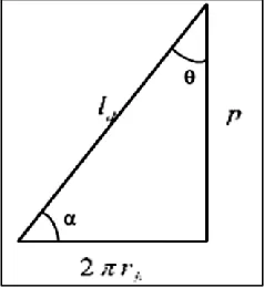
C. Length and Height of a Helical Shaped coil
Let us assume
R
is the radius vector, P is the distance between two successive turns. Total untwisted length of the coil [20],(15)
Height of the coil can be calculated as,
( ) (16)
(a) (b)
Fig. 2 Schematic diagram of helical coil (a) internal dimension and (b) overall view
D. Effect of Twist on the Length of Strand
Fig. 3 shows the effect of twisting on the length of strand [11, 12]. With simple twisting each strand will stay within one such shell at a radius rb and thus will be longer than
the overall bundle by a factor of
√ ( )
(17)
where, is the untwisted length of the strand per turn, is the bundle radius of a litz wire, is the pitch (i.e., vertical lift of the wire per turn after twisting) and
, being the helix angle by which the strand is twisted.
Fig. 3The effect of twisting on the length of the strand
Let us consider that a total of number of twisting to be given in the wire for a strand having effective length of
i.e . Therefore the total twisted length of a coil
( ) √ ( ⁄ ) (18)
It has been found in the literature of litz wire that normally for thick wire twelve turns per feet and for thinner wires 100 to 200 turns per feet of twisting are preferred.
E. Insulation Dimension of the Strands
The insulation thickness [12] of the strand can be considered as
(19)
Where B is the minimum insulation thickness in mils ( ), =0.518 for single build insulation and =0.818 for heavy build insulation. AWG stands for American Wire Gauge, which defines nominal
wire diameter in inches as
( )( ).
3. Resistance calculation
The overall dc resistance of a twisted bundle is the parallel combination of resistances of many such strands, each at a different radius. Because of the different resistance of strands at different radii, the dc current will not be exactly equal for each strand. However, the expression for total resistance is greatly simplified by assuming that the dc current flowing in each strand is the same. By performing both the simplified and exact calculations, it is found that the approximation of equal dc strand currents is 2% higher when the pitch is more than six times the diameter of the bundle. The overall dc resistance without twisting can be calculated [12] as:
(20)
where, is the total number of strands present in a bundle, is the diameter of a strand, is the resistivity of the copper wire and is the total length required for maintaining the effective length of the coil to be equal to .
A. DC Resistance of a Twisted Bundled litz wire
In Section II D, it has been noticed that the total length of a strand increases due to the twisting of the wire. This increase in length directly corresponds to the increased dc resistance of a strand. On the other hand, diameter of a strand also increases due to twisting of wires, which in turn reduces the dc resistance. Therefore, it is necessary to obtain the dc resistance correction factor due to twisting of the wire. The overall bundle diameter
depends on the strand packing factor ( ) like the following:
(21)
Where, is the overall bundle area ( ) and is the sum of cross sectional areas of all the strands with each strand area taken perpendicular to the bundle but not perpendicular to the strand [21].
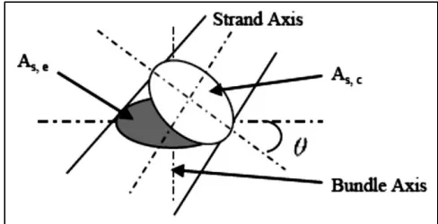
Fig. 4Cross sectional view of a strand after twisting
Thus, the area of each strand is taken at a different angle, θ to the strand axis, resulting in an elliptical area, as shown in Fig.4. For the purpose of simplicity the packing factor is assumed to be constant and independent of the pitch. However, the bundle diameter increases with twisting. Now, consider the situation when a bundle of n strands are twisted. In the bundle cross section, each strand area becomes elliptical at an angle θ as shown in Fig.4. Note that at different radii, θ have different values. Cross sectional area perpendicular to the strand can be calculated as below.
(22)
Where, is the cross sectional area of the strand perpendicular to the strand and is the cross sectional
area of the strand perpendicular to the bundle axis. As is independent of pitch,
(23)
Where, is the overall bundle area when there is no twisting.
Therefore, the total cross sectional area of the strand perpendicular to each strand is calculated as follows [11]:
(24)
∑ (25)
This can be approximated as
∫ ( ) (26)
Combining (24) and (26) bundle diameter with twisting can be found
√( ) (27)
Since, √ (28)
√ ( ) (29)
The DC power loss of a single strand can be calculated as
(30)
Where is the rms current in each strand.
In the cross section of a twisted bundle, DC power loss per unit area is-
(31)
Integrate over the bundle to get the total DC power loss
∫ (
)
(32)
Where, is DC loss of the bundle without twisting. Now, the DC resistance ( ) of the twisted bundle is
given by
( ) (33)
Where represents the DC resistance without
twisting.
B. AC Resistance of a Multi-Strand litz wire
In this section, an attempt is made to relate AC resistance with the skin effect factor ( ). If a conductor is composed of one or more concentric circular elements, then the centre portion of the conductor will be enveloped by a greater magnetic flux than those on the outside. Consequently, the self -induced back emf will be greater towards the centre of the conductor, thus, causing the current density to be less at the centre than the conductor surface. This extra concentration at the surface is known as skin effect, the results in an increase in the effective resistance of the conductor. The skin effect factor ( ) is
more in case of high frequency resonant inverter fed induction heated system [23, 24, 25].
The skin effect factor ( ) is expressed as [13, 14, 15, 16, 21, 22]:
( ) (34)
Where
, (35)
Where is frequency (Hz), is factor determined by conductor construction, ( =1 for circular, stranded, compacted and sectored) and is the DC resistance at normal operating temperature. Therefore, depends on two parameters, DC resistance and operating
frequency .
( ) (36)
Moreover, varies with the number of twist of the
stranded litz wire. Therefore, it is essential to obtain a value of number of twist for which becomes minimal
at a constant operating frequency. To achieve the same, it is considered that
or, * ( )+ (37)
Or, ( )
(38)
Now, combining the equations (34) through (39), optimal value of AC resistance may be obtained using the expression –
( )
[( ) ] , (39)
Where, all the notations have their usual meaning and discussed in the text.
4. Analysis & calculation of abject parameters
When an alternating current flows in a coil placed in close proximity to a conducting surface, the magnetic field of the coil will induce circulating (eddy) current in that surface. The magnitude and phase angle of this induced eddy current will determine the loading on the coil and thus its effective impedance. Induction heating is an electromagnetic phenomenon.
Following are the most important characteristics of induction heating:
The current flows mostly through the outer surface of the metal disc/object and heats the surface.
Here, the heat energy is transferred to the metal at an extremely rapid rate. The rate is faster than any conventional method of heating metals. This is due to the fact that heat is developed directly within the metal surface rather than being transmitted through the surface as in resistance heating.
The heat is generated without any physical contact between the source and the metal object being heated for the magnetic field is capable to penetrate any non-metallic medium placed between the heating coil and the material being heated.
Unlike conventional methods the disc surface can attain extremely high temperature if induction be continued.
A. Factors Affecting the Eddy Current in the Object:
There will be many different factors that will affect the eddy current induced in the metallic object and these are outlined below.
Material conductivity ()
The conductivity of the material of the metal surface has a direct effect on the flow of eddy current. The higher the conductivity of the material the larger will be the flow of eddy currents on the surface.
Permeability of the material ()
Permeability is the property of a material describing the ease with which it can give passage to magnetic flux. For non-ferrous metals such as copper, brass, aluminium etc. and for austenitic stainless steels, the permeability is almost the same as that of free space i.e. the relative permeability will be very close to unity. For ferrous metals, however, the value of relative permeability will be quite high, of the order of several hundred. The value of has a significant influence on the magnitude of the induced eddy current.
Operating frequency ()
The response to eddy current is significantly affected by the frequency chosen. Fortunately, however, this is an item which can be easily controlled.
Geometry of the object
Practical heating surface is neither flat nor of infinite size. Besides, geometrical features such as curvature, edges, grooves etc. will exist and they all will affect the eddy current response. Also, if the material thickness be less than the corresponding effective depth of penetration then this will also unduly affect the eddy current produced. Depth of penetration ()
The eddy current density and hence the amount of heat produced, is greatest on the surface of the metal being heated and then declines with the depth. It is convenient to define mathematically the standard depth of penetration where the eddy current is 37% of its surface value and may be expressed as:
(40)
Equation (40) reveals that following are the factors that affect the depth of penetration.
i) decreases with the increase of frequency ii) increases with the increase of resistivity iii) decreases with the increase of permeability.
A. Determination of Effective Resistance and Reactance of the Secondary Metallic Object
As induction heating is an electromagnetic phenomenon, the effective resistance and reactance of the secondary metallic object referred to the heating coil side can be derived from the fundamental electromagnetic field theory. This derivation is made in three steps as outlined below:
Calculation of the magnetic field due to a flat helical coil.
Calculation of the induced emf in the object due to the magnetic field created by the coil.
Calculation of the equivalent parameters of the object.
Calculation of magnetic field H due to helical coil:
For height/radius =14 or more, the magnetic field intensity for a solenoid or helical coil [20].
(41)
Here, H is the height of the coil and I is the current through the coil.
Calculation of the induced emf in the secondary metallic object:
The induced emf in the object is given by,
(42)
Now for the object N=1. Therefore,
(43)
Referring back this voltage to the side of the heating coil of ‘N’ number of turns, the reflected value of this induced emf due to the flux in the object may be written as [8]
( ) V/m (44)
Substituting Hm from (41),
( ) (45)
The equivalent impedance of the object,
Ω/m (46)
Substituting from (45),
( ) Ω/m (47)
Ω/m = R’object+ jX’object (48)
The equivalent resistance of the object per unit length,
Ω/m (49)
and the equivalent reactance of the object per unit length,
Ω/m (50)
From (49) & (50), the total equivalent resistance and reactance of the object after replacing ω by 2πf where f is the switching frequency
(51)
and
(52)
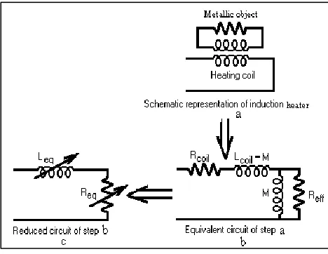
5. Equivalent circuit model of induction heating system
The helical shaped heating coil acts as the primary winding of a transformer while the secondary metallic objects would behave as its closed secondary winding as shown in Fig.5. The resistance of the heating coil (Rcoil) changes with frequency due to skin and proximity effects and also due to the change in temperature. Lcoil is the self inductance of the heating coil. M represents the mutual inductance between heating coil and metallic objects. Reff is the effective resistance of the metallic object when referred to the heating coil side. The metallic object inductance referred to the heating coil side is L2 = M, as there is no physical winding on the metallic object side. The basic circuit and the simplified equivalent circuits are well explained in Fig.5. The heating coil and the heating object (load) can be represented by an equivalent series combination of Req and Leq, where the values of Req and Leq are as follows:
(53)
(54)
Where
√( )
For induction heating as the resistance (Reff) and the magnetizing reactance (M) of the secondary metallic object are of same magnitude, the equations (53) and (54) can be rewritten as:
Fig. 5 Equivalent Circuit model for induction heater.
(55)
(56)
6. Sample calculations for heating coil
In the present paper, an attempt is made to obtain inductance and AC resistance of a heating coil for industrial application of induction heater operating at a high frequency. The heating coil is made up of litz wire having multiple strands and multiple layers (refer to Fig. 1) and the material is considered to be copper. For the strand size 26 AWG, operating frequency 33.33 kHz and number of twist equals to 100 per feet, Table I shows the physical dimensions of a twisted litz wire.
From the physical dimensions given in Table I of the litz wire with different layers & strands, a comparative study has been made between the values of inductance and AC resistance in the Table II and Table III respectively.
Table I Dimensions of the twisted litz-coil for the physical setup
Physical parameters
(Layers, Strands)
(1, 4) (2, 7) (3, 19) (4, 37)
Radius of a strand, rs (m) 0.0002 0.0002 0.0002 0.0002
Number of helical turns, N 200 200 200 200
Coil radius of the spiral coil, R (m) 0.04 0.04 0.04 0.04
Twisted Bundle dia. of the litz -wire, db (m) 0.001094 0.001433 0.002925 0.005015
Intermittent space between the winding of
spiral coil, S (m) 0.001094 0.001433 0.002925 0.005015
Packing Factor (Ka) 0.686413 0.77778 0.76 0.755102
Height of helical coil, H (m) 0.43772 0.57313 1.16996 2.00613
Total length of twisted helical coil, ltot (m) 50.26578 50.26599 50.2676 50.27172
GMD of the coil, Ds (m) 0.000349 0.000441 0.000767 0.001079
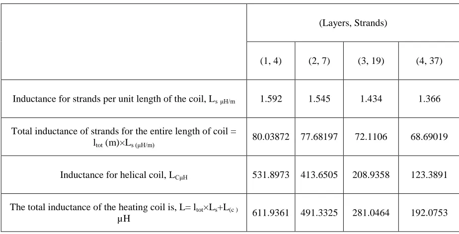
Table II Inductance of the multi-layered, helical shaped twisted litz-coil
(Layers, Strands)
(1, 4) (2, 7) (3, 19) (4, 37)
Inductance for strands per unit length of the coil, LsμH/m 1.592 1.545 1.434 1.366
Total inductance of strands for the entire length of coil =
ltot (m)×Ls (μH/m) 80.03872 77.68197 72.1106 68.69019
Inductance for helical coil, LCμH 531.8973 413.6505 208.9358 123.3891
The total inductance of the heating coil is, L= ltot×Ls+L(c )
Table-III A.C resistance of the multi-layered, helical shaped twisted litz- coil with skin effect
(Layers, Strands)
(1, 4) (2, 7) (3, 19) (4, 37)
Untwisted d.c resistance, Ω 1.683457 0.961979 0.354425 0.182017
Twisted d.c resistance, Ω 2.110158 1.338588 0.739825 0.569948
AC resistance with skin
effect, Ω 1.273142 1.997685 3.551112 4.536025
Skin depth δ, m 0.000362 0.000362 0.000362 0.000362
AC resistance with skin
effect & skin depth , Ω 0.696603 0.532015 0.260629 0.152009
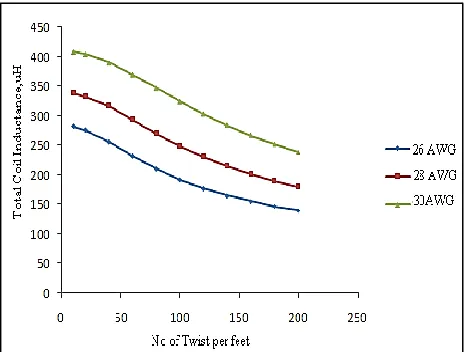
Fig. 6 shows the relationship of the coil inductance with number of twist of different litz wire constructions for different AWG of the strand. It is observed that with twist per feet increases for same strand size (AWG), the coil inductance decreases due to the increase of twisted bundle diameter of the litz wire. Again as the strand size (AWG) increases, coil inductance increases as twisted bundled diameter falls which decrease the height of the litz wire.
Fig. 6 Coil inductance variation with number of twist for 4-layered, 37-stranded litz wire
AC resistance for any strand size is found to be decaying for the increment of number of twist per feet for the same reason (Refer to Fig. 7).
The similar experiment has been conducted by varying the strand size and number of strands for a constant operating frequency (33.33 kHz). The variation of AC resistances with the number of twist per feet was found to be similar in nature for different number of strands.
Fig. 7 AC resistance variation with the number of twist for 4-layered, 37-stranded litz wire
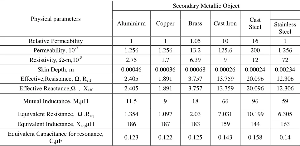
Table-IV Parameters of secondary metallic objects & equivalent resistance & inductance of litz wire
Physical parameters
Secondary Metallic Object
Aluminium Copper Brass Cast Iron Cast
Steel
Stainless Steel
Relative Permeability 1 1 1.05 10 16 1
Permeability, 10-7 1.256 1.256 13.2 125.6 200 1.256
Resistivity, Ω-m,10-8 2.75 1.7 6.39 9 12 72
Skin Depth, m 0.00046 0.00036 0.00068 0.00026 0.00024 0.00234
Effective,Resistance, Ω, Reff 2.405 1.891 3.757 13.759 20.096 12.306
Effective Reactance,Ω , Xeff 2.405 1.891 3.757 13.759 20.096 12.306
Mutual Inductance, M,µH 11.5 9 18 66 96 59
Equivalent Resistance, Ω ,Req 1.354 1.097 2.03 7.031 10.199 6.305
Equivalent Inductance, Xeq,µH 186 187 183 159 144 163
Equivalent Capacitance for resonance,
C,µF 0.123 0.122 0.125 0.143 0.158 0.14
It is obvious that for maximizing the heat generated in the induction heated system, the coil inductance should be high. But at the same time the AC resistance should also be low to minimize the skin effect losses. With the practical feasibility of design considered, the number of twist per feet is selected as 100. As stated, an important aspect of designing a litz wire for induction heating at industrial applications is to minimize the losses due to skin effect, which largely depends on operating frequency. Therefore, variation of AC resistance was studied varying the operating frequency between 20 – 100 kHz. This study was made for a twisted litz wire of 100 twists per feet. Fig. 8 shows the variation of AC resistances with the operating frequency for strand sizes, 26, 28 and 30 AWG, respectively. Since AC resistance increases due to the increase in frequency, operating frequency in the lower side will be more economical and loss free.
7. Sample calculations for secondary metallic object
When the high frequency induction heating system is loaded with some secondary metallic objects, the effective values of AC resistance and inductance of litz wire are changed. The experiment has been conducted with different metallic objects. With the coil radius & height of the coil determined as above, the ratio of H to R is more than 50. Therefore, the analysis presented in the section-IV is applied here to get the parameters of the secondary metallic objects for induction heated system. The working frequency is taken 33.33 kHz as earlier. Finally, with the effective values of resistance and inductance of the different secondary metallic objects, the
equivalent on load values of litz wire inductance & AC resistance are determined.
In the Table-IV, parameters of secondary metallic objects have been shown. For industrial application of induction heated system, stainless steel is preferred as secondary metallic object and therefore, the equivalent coil inductance & AC resistance have been taken as 163µH & 6.305Ω respectively.
8. Simulation of high frequency resonant inverter induction heated system
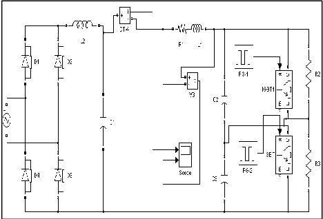
The circuit configuration shown in Fig. 1 has been simulated first by PSIM and then by MATLAB-SIMULINK. The parameters of the inverter configuration have been shown in Table V.
Table V: Input parameters of simulation
Filter circuit components L2=100µH, C1=5µF
Heating coil parameters
(reflected values) 163µH, 6.305Ω
Charging capacitors (C2 & C3) 0.4µF
Snubbed resistors (R2 & R3) 470 Ω
The circuit diagram used for the PSIM simulation work has been shown in the Fig. 9. In the Fig. 10, coil current waveform is shown.
Fig: 9 Circuit diagram for P-SIM Simulation of mirror inverter using IGBT
Fig. 10 Current waveform through the coil
The same circuit configuration is also simulated in MATLAB-SIMULINK environment. The circuit is shown in Fig. 11 & the corresponding waveform for coil current is shown in Fig.12.
Fig: 11 Circuit diagram for SIMULINK simulation of mirror inverter using IGBT
Fig. 12 Current waveform through the coil
Conclusions
Due to the inherent advantages, induction heated system based on high frequency mirror inverter are equally effective for industrial applications as it is for domestic equipments. To reduce the skin effect and proximity-effect losses, the heating coil is made of litz wire. However, choice of a litz wire construction is difficult and computation of AC resistance, inductance of a litz wire is complex. In the present paper, an attempt is made todesign a litz wire for industrial application. Inductance is calculated for four different litz wires, 1-layer-4-stranded, 2-layer-7-1-layer-4-stranded, 3-layered-19-stranded and layered-37-stranded. The physical dimensions of the 4-layered-37stranded litz wire has found to be largest compared to the others and thus suitable for large industrial induction heated system.
References
1. P. K. Sadhu, N. Jana, R. Chakrabarti, and D. K. Mittra (2005),A Unique Induction Heated Cooking Appliances Range Using Hybrid Resonant Converter , Int. Journal of Circuits, Systems and Computers, World Scientific, vol. 14, no. 3, pp. 619-630, June.
2. P. K. Sadhu, R. N. Chakrabarti, and S. P. Chowdhury (2010), An improved high frequency inverter circuit arrangement.,” Patent No. 244527 date of grant 09th December, Patent Office,Government of India
3. P. K. Sadhu, N. Pal, D. Sinha, and A. Bandyopadhyay (2010), Energy Efficient Induction Heated Cooking – Range using MCT baesd Hybrid Resonant Converter, Proc. IEEE on 2nd International Conference on Computer and Automation Engineering (ICCAE 2010), vol 5, February, pp. 637-641.
4. A. Okuno, H. Kawano, J. Sun, M. Kurokawa, A. Kojina and M. Nakaoka.(1998), Feasible development of soft-switched SIT inverter with load-adaptive frequency-tracking control scheme for induction heating, IEEE Trans. Ind Appl., vol 34,no. 4, pp. 713-718.
5. S. A. Gonzalez, M. l. Valla and C. H. Muravchik (2001), Analysis and Design of Clamped-Mode Resonant Converters with Variable Load, IEEE Transactions on Industrial Electronics, vol.48, no. 4, August, pp. 812-819. 6. W. E. Frank, Reuben Lee (1982), New Induction Heating
Transformers, IEEE Transactions on Magnetics, vol 18,no.6.pp.1752-1754.
7. P. K. Sadhu, N. Pal, R. N. Chakrabarti and T.K Chatterjee (2007), Performance analysis of HF mirror inverter for energy efficient induction cooker appliance range, in Proc. Int Conf. on Modeling and Simulation (MS’07), University of Calcutta, December, pp. 444-448.
8. N.Pal, P. K. Sadhu, R. N. Chakrabarti (2009), Choice of Pan Material in radio-frequency Mirror Inverter Induction Cooker, Journal of Institution of Engineers (I), Vol 89, pp 09-18 ,March 18.
9. Charles R. Sullivan (2001), Member, IEEE Cost-Constrained Selection of Strand Diameter and Number in a Litz wire Transformer Winding, IEEE Trans. Power Electronics,vol-16 ,no-2, pp.281-288.
10. Charles R. Sullivan (1999), Member, IEEE Optimal Choice for Number of Strands in a Litz wire Transformer Winding,
IEEE Trans. Power Electronics ,vol-14 ,no-2,pp.283-291. 11. Xu Tang and Charles R. Sullivan (2003),Stranded Wire
With Uninsulated strands as a Low-Cost Alternative to Litz Wire, Proc. IEEE Power Electronics Specialists Conf .,pp-1-7.
12. Xu Tang and C. R. Sullivan (2004), Optimization of stranded-wire windings and comparison with Litz wire on the basis of cost and loss,Proc. IEEE Power Electronics Specialists Conf., pp. 854 – 860.
13. Akiba Yutaka and Hirota Kazuo (1985), Litz wire for degreasing skin effect at high frequency, United States Patent no. 4549042.
14. Acero, J.; Alonso, R.; Burdio, J.M.; Barragan, L.A.; Puyal, D. (2006), Frequency-dependent resistance in Litz-wire planar windings for domestic induction heating appliances,
IEEE Trans. on Power Electronics, vol 21, no. 4, pp. 856 – 866,July.
15. Koertzen, H.W.E.; van Wyk, J.D.; Ferreira, J.A.(1992), An investigation of the analytical computation of inductance and AC resistance of the heat-coil for induction cookers”
Industry Applications Society Annual Meeting, vo1 l. pp.1113 - 1119 .
16. J. A. Ferreira (1992), Analytical computation of ac resistance of round and rectangular litz wire windings, in
Proc. IEE Proc. B, Electric Power Applications, vol.139, no.1, pp. 21–25.
17. D. P. Kothari and I. J. Nagrath (2003), Modern power system analysis, TMH, New Delhi,Chapter 2.
18. Herbert B. Dwight (1945), Electrical coils and conductors, MacGraw-Hill, Chapter 4.
19. H. A. Wheeler (1928), Simple inductance formulas for radio coils, Proc. of I.R.E., vol. 16, no.10, October, pp.1398-1400.
20. Chattyopadhyay, Rakshit (1999), Electricity & Magnetism,
Central Book Agency Books Allied (P) Ltd , pp.145-154. 21. K. W. E. Cheng and P. D. Evans (1994), Calculation of
winding losses in high frequency toroidal inductors using single strand conductors, Proc IEE. of Power Electronic Applications Conf., vol. 141, no. 2, pp. 52-62.
22. P. K. Sadhu, N. Pal, R. Chakrabarti, and D. K. Mittra (2006), A dynamic model for the simulation of induction cooktop, J. Industrial Engineering, Vol XXXV, No 6 , pp. 37-41.
23. F. P. Dawson and P. Jain. (1991), A comparison of load commutated inverter systems for induction heating and melting applications, IEEE Trans. Power Electronics., vol 6, no.3, pp. 430-441.
24. P. K. Sadhu,N. Pal, A. Bandyopadhyay, and D. Sinha (2010), Review of Induction Cooking – a Health Hazards Free Tool to Improve Energy Efficiency as Compared to Microwave Oven, Proc. IEEE 2nd International Conf. on
Computer and Automation Engineering (ICCAE 2010) , Volume 5, February, pp. 650-654.