Model Reference Adaptive System (MRAS)
Technique For Sensorless Scalar Control Of
Induction Motor
R B R Prakash, Dr. P Srinivasa Varma, Dr. A Pandian, K P Prasad Rao
Abstract: This paper describes a closed loop v/f control of induction Machine with Model Reference Adaptive System (MRAS) based sensorless rotor speed estimation technique. Generally to get the speed information of induction motor, tachometers are used. Speed sensor requires extra space for mounting and care and hence increases the cost and the size of the system. To make the drive mechanically more vigorous, we need to avoid the speed sensor. Researches introduced different sensor less methodologies to get the estimated rotor speed of Induction Motor (IM) drives. Such methods are divided into two types, one is signal inoculation method and another is model based method. In the Model-Based technique, MRAS is the simplest approach which is more effectively applied for estimation of rotor speed. Theoretical basis of scalar control and MRAS is described in detail and it is instigated in MATLAB/SIMULINK.
Keywords: Model reference Adaptive System, PI Controller, Induction Motor, v/f control, sensorless rotor speed estimation, parks transformation
————————————————————
1.
INTRODUCTION
For variable speed applications, AC machines are most commonly used in industry. Among the AC machines, Induction Motors are maintenance free; cost effective which is more suitable for adjustable speed applications in terms of weight, speed of rotation, size, weight, controllability, efficiency and reliability [1]. The variable speed drives (VSDs) are used in all manufacturing and processing industries to control the speed of IM driving loads reaching from pumps and fans to complex drives[2]. IMs do not have innately the ability of adaptable speed operation. May be due to this reason, DC motors were used in most of the electrical drives. Due to the recent advancements in the speed control methods, IM is using almost in all the electrical drives [3]. Different techniques of speed control of an IM such as variable stator voltage, frequency variation, constant V/f control, variable rotor resistance, pole changing, slip retrieval method. Closed loop constant V/f speed control method is used mostly. In this method to maintain flux constant we need to keep the V/f ratio constant so that unaffected maximum torque is attained [4]. Constant volts-per-hertz (v/f) control is more robust and simple control structure at the cost of reduced dynamic performance, which is acceptable for applications like pump and fan drive, and tolerable for other application if cost is an issue. These cost-saving features are definitely essential for small power applications. At higher power, the power components themselves dominate the system cost,
authorizing the execution of more refined control methods which serve to overcome the disadvantages of v/f control i.e. reduced dynamic performance. The cost advantage makes scalar control very striking for small power applications, while their vigor helps its use at high power, when fast response is not required. Such systems give a substantial portion in the market with speed sensor less drives. On-going study has concentrating on the removal of the tachometer at the shaft of the machine without failing the performance of the drives. By using sensor less methodology the difficulty of hardware is reduced and inferior cost, reduced size of the drive, sensor cable is eliminated, better noise exception, reliability of the drive increased and less maintenance requirements. Mostly in hostile environment operation motor without speed sensor is more suitable rather than sensor approach.
2.
SCALAR
CONTROL
TECHNIQUE:
In scalar control technique, speed is controlling by linearly changing the voltage and the frequency in order to sustain the air-gap flux constant [6-7]. In constant V/f speed control, a variable voltage and variable frequency is applied to the induction motor. Both the VSI (Voltage Source Inverter) and CSI (Current Source Inverter) are used in variable speed ac drives. Block diagram of Conventional closed loop v/f control of IM with tachometer is shown in below figure.1
Wref *
Wr
PI CONTROLLER
Wr
Wsl SPWM VSI
Tachometer INDUCTION
MOTOR
v/f Control
Va Vb Vc Limiter
Vs* S1 S3 S5
Integrator Ws e
Te
Figure .1 Conventional v/f Closed Loop control of IM with Tachometer
A Tachometer or a speed encoder is used to get the
information of the actual speed (r) of the IM and then it is
compared with the reference speed (ref). The difference
between the two speeds will generates an error speed and
————————————————
R B R Prakash, Department of Electrical and Electronics
Engineering, Koneru Lakshmaiah Education Foundation,
Vaddeswaram, AP, India. E-mail: [email protected]
Dr. P Srinivasa Varma, Department of Electrical and Electronics
Engineering, Koneru Lakshmaiah Education Foundation,
Vaddeswaram, AP, India. E-mail: [email protected]
Dr. A Pandian, Department of Electrical and Electronics
Engineering, Koneru Lakshmaiah Education Foundation,
Vaddeswaram, AP, India. E-mail: [email protected]
K P Prasad Rao, Department of Electrical and Electronics
Engineering, Koneru Lakshmaiah Education Foundation,
Vaddeswaram, AP, India. E-mail:
obtained speed error is send to proportional Integral controller (PI) [5]. The output of the PI Controller is the torque command which is directly proportional to the slip
speed command (ωsl). The slip speed command is limited
by using limiter. Synchronous speed (ωs) is achieved by
summing the actual rotor speed command (ωr) and the slip
speed command (ωsl) i.e. (ωr = ωs + ωsl). To determines the
inverter frequency command (fs ).
The voltage command (Vs*) is generated from frequency
* (1) s s V
If the air gap flux () maintained constant which can be
achieved only by maintaining the v/f ratio constant, which
further leads the unaffected maximum torque. Voltage (Vs*)
and Angle (e) is used to produce the 3 sinusoidal reference
voltages (Va*, Vb*, Vc*) as in the Equation (3)
In Sinusoidal Pulse width modulation (SPWM) technique, reference wave is compared with carrier wave to produce triggering pulses. When reference is greater than carrier the required pulse is generated. The generated triggering pulses are applied to VSI which converts DC into AC of required frequency and amplitude. Modulated AC output of VSI fed to the induction motor.
3. MRAS SPEED ESTIMATION TECHNIQUE:
To make the drive mechanically more vigorous, we need to avoid the speed sensor. Researches introduced different sensor less methodologies to get the estimated rotor speed of IM drives [8]-[11]. Such methods are divided into two types: one is signal inoculation method and another is model based method. In the Model-Based technique, MRAS is the simplest approach which is effectively applied for speed estimation. In this paper, Rotor Flux based sensor less approach is used to form MRAS for rotor speed estimation was studied. MRAS structure which is more effective and difficulty is reduced. MRAS approach consists of two models. In reference model (voltage model) the
quantity to be estimated (ωr) will not be considered.
Adaptive model (current model) which does involves the
quantity to be estimated (ωr).The voltage model output is
related with the output of an adjustable model till the error difference between the voltage model and adjustable model disappear to zero and with the correct value of rotor speed
(ωr), the rotor fluxes determined from the two models
(voltage model and adjustable model) should match. An adaptation system with PI control is used to adjust the rotor
speed (ωr) value until the two flux values equal. In figure
2(a) and figure 2(c), Basic diagram and block diagram of MRAS is shown. In figure 2(b) and figure 2(d), Transformations (3phase to 2phase) [5] and Rotor Flux Linkage of MRAS is shown.
Wref *
Wr
PI CONTROLLER
Wr
Wsl SPWM VSI
INDUCTION MOTOR v/f Control Va Vb Vc Limiter Vs* S1 S3 S5 Integrator Ws
e Te MRAS Wr Vabc Iabc Measured Motor Terminal Voltages and Currents Figure .2(a) MRAS Speed Estimation Technique3 2 3 2 INDUCTION MOTOR PHASE-A PHASE-B PHASE-C
Vas Vbs Vcs Ias Ibs Ics
s
V Vs Is Is
TRANSFORMATION abc
Figure. 2(b) Transformation (abc to αβ) of Voltages and Currents
Transformation of Voltages (abc to αβ):
Transformation of Currents (abc to αβ):
(2)
e s
dt
* * * * * *2
sin
2
2
sin
(3)
3
2
2
sin
3
a s e
b s e
c s e
V
V
V
V
V
V
01
1
1
2
2
2
3
3
0
3
2
2
1
1
1
2
2
2
s as s bs cs
V
V
V
V
V
V
01
1
1
2
2
2
3
3
0
3
2
2
1
1
1
2
2
2
Machine Parameters
Parameters Values
No of Poles Pairs (P) 2
Frequency(fs) 60Hz
Hp 3
Voltage(V) 220V
Resistance of Stator (Rs) 0.435
Resistance of Rotor (Rr) 0.82 Stator Leakage Reactance (Xsl) 0.755 Rotor Leakage Reactance (Xrl) 0.755
Mutual Reactance(Xm) 26.13
Rotor Inertia(J) 0.089kg-m2
Table1. Induction Motor Parameters
REFERENCE MODEL ADAPTIVE
MODEL MECHANISMADAPTIVE
Vs
Is
Wr Wr
r
^
r
Figure. 2(c) Basic Structure of MRAS
Adaptive Model Equations:
^ ^ ^
1
(6) m
dr ds r qr dr
r
L i
T
Tr
^ ^ ^
1
(7) m
qr qs r dr qr
r
L i
T
Tr
Reference Model Equations:
[
(
)
]
(4)
r
dr ds s s ds
m
L
d
V
R
L
i
L
dt
[
(
)
]
(5)
r
qr qs s s qs
m
L
d
V
R
L
i
L
dt
PI
CONTROLLER Wr
r
^
r
Limiter^
dr
^
qr
dr
qr
Figure. 2(d) Rotor Flux Linkage of MRAS
Adaptive mechanism for Rotor Speed:
1
(8)
r
K
pK
iS
^ ^
(9)
qr dr
dr qr
where
Vds, Vqs - Stator d-axis & q-axis voltages
Ids, Iqs - Stator d-axis and q-axis currents
Ls, Lr, Lm - Stator, Rotor and mutual inductance
dr, qr - rotor d-axis and q-axis flux linkages
Tr= Lr/Rr -Rotor time constant
=1-(Lm
2
/ LsLr) - Motor leakage coefficient
4. SIMULATION RESULTS:
Simulation of sensorless scalar control of induction motor with
rotor flux based MRAS technique is done in
MATLAB/SIMULINK as shown in below Figure 3(a), Figure 3(b), Figure 3(c), Figure 3(d) by using the induction motor parameters which is shown in Table1.
The result for three cases are specified below Case-1: No Load
Case-2: Under Loaded Condition
Case-3: Due to Step Change in reference speed Command at t=1sec.
Simulation Models:
Figure .3(a) Scalar Control of IM with MRAS Speed Estimation Technique
Figure 3(c) Rotor-Flux Based MRAS Speed Estimation Technique
Figure 3(d) SPWM with 3rd Harmonic Injection Method
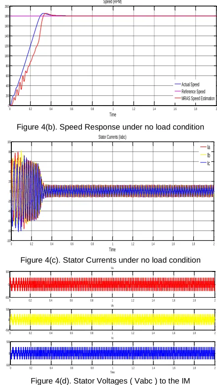
CASE-1: NO LOAD CONDITION
Under no load condition (TL = 0) the torque and speed
response is shown in figure 4(a) & figure 4(b). In figure 4(a),
the reference torque is (TL = 9 N-M) but the actual torque
will take time (t=0.5) to settle at reference torque. In figure 4(b), the actual motor speed will settle at t=0.5 but the estimated rotor speed by using MRAS have some oscillations during starting with delay compared to the actual motor speed. Stator Currents (Iabc) and Stator Voltages (Iabc) under no load as shown in below figure 4(c)
and figure 4(d).
Figure 4(a). Torque Response under no load condition
Figure 4(b). Speed Response under no load condition
Figure 4(c). Stator Currents under no load condition
Figure 4(d). Stator Voltages ( Vabc ) to the IM
CASE-2: UNDER LOAD CONDITION AT T=1SEC
Under loaded condition, Load (TL = 9 N-M) is applied as a
step input at t=1sec, the torque and speed response as shown in figure 5(a) & figure 5(b). In figure 5(a), the
reference torque is TL = 9 N-M but the actual torque is settle
at time (t=0.5) and maintain constant upto t=1sec. At t=1sec step input is applied then actual torque is raised and settle at reference torque. In figure 5(b), the actual motor speed will settle at t=0.5 but the estimated rotor speed by using MRAS have some oscillations during starting with some delay compared to the actual motor speed. At time t=1sec, due to step input load varies. Due to load variation, the speed is reduced and settled after some time. Stator Currents (Iabc) under loaded condition is shown in figure 5(c).
0 0.2 0.4 0.6 0.8 1 1.2 1.4 1.6 1.8 2
-20 0 20 40 60 80 100 120
Time Electromagnetic Torque {Nm}
Actual Torque Reference Torque
0 0.2 0.4 0.6 0.8 1 1.2 1.4 1.6 1.8 2
0 200 400 600 800 1000 1200 1400 1600 1800 2000
Time Speed (RPM)
Actual Speed Reference Speed MRAS Speed Estimation
0 0.2 0.4 0.6 0.8 1 1.2 1.4 1.6 1.8 2
-100 -80 -60 -40 -20 0 20 40 60 80 100
Time Stator Currents (Iabc)
Ia Ib Ic
0 0.2 0.4 0.6 0.8 1 1.2 1.4 1.6 1.8 2
-500 0
500 Va
0 0.2 0.4 0.6 0.8 1 1.2 1.4 1.6 1.8 2
-500 0 500
Vb
0 0.2 0.4 0.6 0.8 1 1.2 1.4 1.6 1.8 2
-500 0 500
Figure 5(a). Torque Response at TL = 9 N-M
Figure 5(b). Speed Response at TL = 9 N-M
Figure 5(c). Stator Currents at TL = 9 N-M
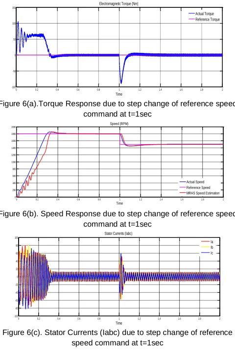
CASE-3: DUE TO STEP CHANGE IN REFERENCE SPEED COMMAND AT T=1SEC
Reference Speed is at 1800rpm and now applied a step input as 1500rpm at t=1sec then the torque and speed response is shown in figure 6(a) and figure 6(b). In figure
6(a), the reference torque is TL = 0 but the torque is settle at
time (t=0.5) and maintain constant upto t=1sec.At t=1sec, step input is applied then actual torque is reduced and settle at reference torque. In figure 5(b), the actual motor speed will settle at t=0.5 but the estimated rotor speed by using MRAS have some oscillations during starting with some delay compared to the actual motor speed. At time t=1sec, due to step input the speed is reduced and settled
after time (t=1.4sec). Stator Currents (Iabc) under step
change of reference speed condition at t=1sec is shown in figure 6(c).
Figure 6(a).Torque Response due to step change of reference speed command at t=1sec
Figure 6(b). Speed Response due to step change of reference speed command at t=1sec
Figure 6(c). Stator Currents (Iabc) due to step change of reference speed command at t=1sec
Comparison of steady state speed and torque responses for different cases is shown in the Table 2.
Conditions Speed (rpm) Torque (Nm) Under No-Load Condition 0.5 0.5 Under Loaded Condition at
t=1sec 1.2 1.2
Step Change of Reference
Speed Command at t=1sec 1.4 1.4 Table2. Comparison of Speed and Torque Response at steady state
for different cases
CONCLUSION:
This paper presents a scalar control (v/f) of IM using sensorless rotor flux based MRAS technique. In simulation, MRAS speed estimation is done for different cases and obtained results is shown above. Rotor flux based MRAS technique which will reduce hardware complexity and cheaper cost, reduce size of the drive machine, elimination of the sensor cable, better sound protection, and improve consistency and less maintenance requirement.
REFERENCES
[1] J. Sathiswar, C. Saravanan and S. Raja,
"Performance of three phase IM using modified stator winding," International Journal of Computer Applications, vol. 46, pp. 1-4, 2012.
0 0.2 0.4 0.6 0.8 1 1.2 1.4 1.6 1.8 2
-20 0 20 40 60 80 100 120
Time Electromagnetic Torque (Nm)
Actual Torque Reference Torque
0 0.2 0.4 0.6 0.8 1 1.2 1.4 1.6 1.8 2
0 200 400 600 800 1000 1200 1400 1600 1800 2000
Time Speed (RPM)
Actual Speed Reference Speed MRAS Speed Estimation
0 0.2 0.4 0.6 0.8 1 1.2 1.4 1.6 1.8 2
-100 -80 -60 -40 -20 0 20 40 60 80 100
Time Stator Currents (Iabc)
Ia Ib Ic
0 0.2 0.4 0.6 0.8 1 1.2 1.4 1.6 1.8 2
-100 -50 0 50 100 150
Time Electromagnetic Torque (Nm)
Actual Torque Reference Torque
0 0.2 0.4 0.6 0.8 1 1.2 1.4 1.6 1.8 2
0 200 400 600 800 1000 1200 1400 1600 1800 2000
Time Speed (RPM)
Actual Speed Reference Speed MRAS Speed Estimation
0 0.2 0.4 0.6 0.8 1 1.2 1.4 1.6 1.8 2
-100 -80 -60 -40 -20 0 20 40 60 80 100
Time Stator Currents (Iabc)
[2] R. Saidur, S. Mekhilef, M. B. Ali, A. Safari and H. A. Mohammed, ―Applications of variable speed drive (VSD) in electrical motors energy savings‖, Renewable and Sustainable Energy Reviews, vol.16, pp. 543–50, 2012.
[3] Tiago Henrique dos Santos, Alessandro Goedtel,
Sergio Augusto Oliveira da Silva, Marcelo Suetake, ―Scalar control of an induction motor using a neural sensorless technique‖, Electric Power Systems Research, Vol 108, March 2014, Pages 322-330.
[4] Pandian, A., & Dhanasekaran, ―Performance
analysis of direct torque control of 3-phase
induction motor‖, Journal of Theoretical and
Applied Information Technology, 62(3), 819-824, 2014..
[5] R B R Prakash, Srinivasa Varma P, ―Stability
Enhancement of Wind Power Plant During Abnormal Conditions With Negative Sequence Components Compensation Using STATCOM‖, Journal of Advanced Research in Dynamical and Control Systems, vol 18, 85-95, 2017.
[6] C. O. Adiuku, A. R. Beigand S. K. Kanukollu,‖
Sensorless Closed Loop V/f Control of
Medium-Voltage High-Power Induction Motor with
Synchronized Space Vector PWM,‖ IEEE
GCCConferenceandExhibition,Muscat,Oman,1-4Feb, 2015.
[7] A. M. Garcia, T. A. Lipo and D. W. Novotny, "A
new induction motor V/f control method capable of high-performance regulation at low speeds," Industry Applications, IEEE Transactions on, vol. 34, pp. 813-821, 1998.
[8] J. Holtz, ―Sensorless control of induction motor
drives,‖ Proc. IEEE, vol. 90, no. 8, pp. 1359–1394, Aug. 2002.
[9] V. Vasic and S. Vukosavic, ―Robust MRAS-based
algorithm for stator resistance and rotor speed identification,‖ IEEE Power Eng. Rev., vol. 21,no. 11, pp. 39–41, Nov. 2001.
[10]T. Orlowska-Kowalska and M. Dybkowski,
―Stator-current-based MRAS estimator for a wide range speed-sensorless induction-motor drive,‖ IEEE Trans. Ind. Electron, vol. 57, no. 4, pp. 1296–1308, Apr. 2010.
[11]J. Guzinski and H. Abu-Rub, ―Speed sensorless IM
drive with predictive current controller,‖ IEEE Trans. Ind. Electron., vol. 60, no. 2, pp. 699–709, Feb. 2013.
[12]Krishna Manjusha Kondapi, R. B. R. Prakash,