Kalidass et al. World Journal of Engineering Research and Technology
ANFIS CONTROLLER BASED PF IMPROVEMENT FOR
INDUCTION MACHINE USING FLYING CAPACITOR MULTI
LEVEL INVERTER
*1D. Kalidass, 2S. Gokul Raj, 3A. Gnanaprakash and 4M. Arunchandru
1
Assistant Professor, EEE Department, Muthayammal College of Engineering, Rasipuram.
2,3,4
UG Students, EEE Department, Muthayammal College of Engineering, Rasipuram.
Article Received on 04/02/2019 Article Revised on 57/02/2019 Article Accepted on 17/03/2019
ABSTRACT
Energy thing development presents familiar blessings to keep away
from bad electricity aspect effect and to reduction bill fee. Passive
and active strength thing correction are the two techniques presently
the use of energy element correction strategies. This thesis try to
develop an inverter with applied active strength issue correction
method for improve of the strength trouble. MATLAB software program application is used
to layout ANFIS controller to manipulate electricity element on induction machine with the
aid of using modern-day-day and voltage supply inverter from single section rectifier. The
combination of modern-day and voltage supply inverter is called Flying capacitor Multi
level inverter. This system integrates the concept of ANFIS and Flying capacitor Multi
level inverter for controlling the output voltage of DC-AC inverter and also looking to
improve an efficiency of the Flying capacitor Multi level inverter via transient operation. in
this planned model, a Flying capacitor Multi level inverter is used for active % and
contemporary and voltage parameter having advantages of being bodily remotes shape, can
function as each step up and step down Flying capacitor Multi level inverter and having
most effective one step processing for modern-day, voltage regulation and percent. A
model for strength aspect Correction may be done the use of the MATLAB software
program.
World Journal of Engineering Research and Technology
WJERT
www.wjert.org
SJIF Impact Factor: 5.218*Corresponding Author D. Kalidass
KEYWORDS: ANFIS Controller, Flying capacitor Multi level inverter, Induction motor, MATLAB, Power Factor Controller.
1. INTRODUCTION
The main goals of this observe is to layout a strength saving scheme for an industrial
distribution network. This may be done by means of lowering the community losses and
improving the main electric load operation to a better efficiency level. The linear aggregate of
genuine electricity and reactive strength is called apparent power. Low power thing isn't that
a great deal problem in domestic‟s location however it will become a trouble in industry in
which a couple of big automobiles are used so there's requirement to correct the electricity
issue. There are numerous advantages to having power thing correction. The strength detail
control is one of the most important instructions in energy electronics research. Lately, the
paintings on this area have been facilitated thru the development of the modern-day supply
inverter using easy switching strategies. In the remaining decade, a few researchers have
manifested hobby in improving the performances of the wound induction tool by way of
manner of using current deliver inverter.
The handiest viable source of excitation in an induction gadget is the stator input. The induction
machine therefore needs to operate at a lagging electricity thing. This strength factor could be
very low at no load and increases to about 85 to 90 percent at full load, the development being as
a result of the multiplied real-energy necessities with increasing load. The presence of air-gap
between the stator coil associated rotors of an induction machine greatly will increase the
reluctance of the magnetic circuit. Induction machine speed can be control via using fuzzy good
judgment controller and the simulation model of Induction machine power the usage of
Matlab/Simulink.
The voltage source inverter (VSI) fed drives are most broadly used in low and medium
electricity applications, however now not used extensively in high power applications.
Nowadays CSI drives are rent self commutating devices together with gate turn-off thyristors
(GTOs) in place of SCRs as within the past. To get stepped forward output currents and
voltages Pulse width modulation (PWM) strategies are used.
The effectiveness of the proposed control was demonstrated through comparison with some
commonly employed control methods, through an extensive set of simulations using
controller based power factor improvement of induction machine by using current source
inverter. But in this paper explain voltage and current is control in the inverter itself and
controlled voltage and current is given to the induction machine to maintain high power
factor through anfis controller.
2. Induction Machine Drive
An electrical motor is such an electromechanical device which converts electrical
electricity into a mechanical strength. Maximum widely used motor is 3 phase induction
machine as this kind of motor does not require any beginning device or we are able to say
they're self beginning induction motor. For better know-how the precept of 3 phase
induction motor, the basic constructional characteristic of this motor need to be known to
us. This Motor consists of two most important elements.
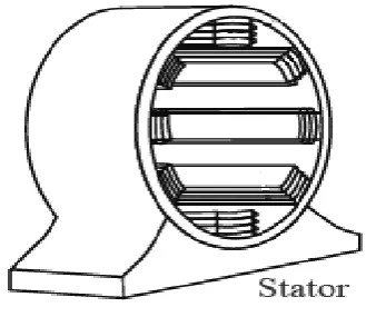
A. Stator
Stator of three phase induction machine is made from numbers of slots to assemble a 3
section winding circuit that is linked to a 3 phase AC supply. Stator diagram is shown in
fig. 1. The 3 section winding are arranged in this kind of way inside the slots that they
produce a rotating magnetic field after 3 Phase. AC supply is given to them.
Fig. 1: Diagram of stator.
B. Rotor
Rotor of 3 phase induction machine includes cylindrical laminated middle with parallel
slots that can bring conductors. Conductors are heavy copper or aluminum bars which suits
in every slots & they're brief circuited via the cease rings. Squirrel cage rotor is shown in
fig. 2. The slots are not exactly made parallel to the axis of the shaft but are slotted a touch
skewed due to the fact this association reduces magnetic buzzing noise & can avoid stalling
.
Fig. 2: Diagram of Squirrel cage rotor.
The difference between the synchronous speed (Ns) and actual speed (N) of the rotor is called
as slip.
The rotational speed of the rotating magnetic field is called as synchronous speed.
Where, f = frequency of the supply
P = number of poles
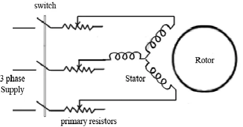
Here, to send the feedback of position and speed of the motor Hall-effect sensors are used. In
addition to the switching for a rated speed of the motor, an additional electronic circuitry
changes the motor speed based on required application. Induction machine drive is shown in
fig. 3. These speed control units are implemented with ANFIS controller to have accurate
control.
3. Controllers 3.1 Anfis Controller
An adaptive neuro-fuzzy inference system or adaptive community-primarily based fuzzy
inference device (ANFIS) is a form of artificial neural network that is primarily based on
Takagi–Sugeno fuzzy inference machine. Because it integrates each neural networks and
fuzzy good judgment standards, it has capability to capture the blessings of each in an
unmarried framework. Its inference machine corresponds to a hard and fast of fuzzy IF–
THEN policies which have studying functionality to approximate nonlinear features.
Consequently, ANFIS is considered to be an established estimator. For the usage of the
ANFIS in an extra green and most beneficial way, one can use the best parameters received
through genetic set of rules.
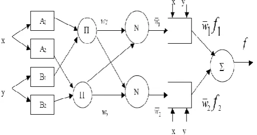
Consider a Sugeno type of fuzzy system having the rule base
1. If x is A1 and y is B1, then f1 = c11x+c12y+c10
2. If x is A2 and y is B2, then f2 = c21x+c22y+c20
The structure of the ANFIS network is shown in fig 4. All computations can be presented in
a diagram form. ANFIS normally has 5 layers of neurons of which neurons in the same
layer are of the same function family.
Fig. 4: Structure of the ANFIS network.
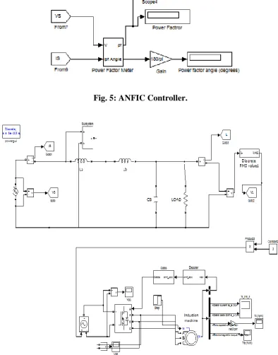
4. Modeling And Simulation Of Power Factor Improvement For Induction Motor The proposed system using ANFIS controller is implemented for power factor improvement
of Induction motor. Fig 5 shows simulation model of ANFIS controller based power factor
improvement of Induction motor. This simulation model consists of four sub blocks named as
Induction model block, Inverter block, controller and subsystem. The subsystem 1 for gate
by using Mat lab. Induction machine blocks itself the EMF, current, voltage and power factor
blocks are present. The duty cycle of the power electronics devices such as MOSFET, IGBT
are controlled by fuzzy controller. The feedback of actual power factor value is taken from
the induction machine and given to the fuzzy controller along with reference value.
Simulation of power factor calculation is shown in Fig 5.
Fig. 5: ANFIC Controller.
The proposed simulation version of induction machine power is showing in fig 6. The
parameters of the percent based Flying capcitor Multi level inverter are designed such, that it
operates in DICM to gain inherent energy component correction at ac mains. Reference
voltage is calculated from controller, as it's miles at once proportional to the carried out dc
hyperlink voltage at a given load. electronic commutation is based totally at the signals of
position sensing corridor sensors placed in the motor.
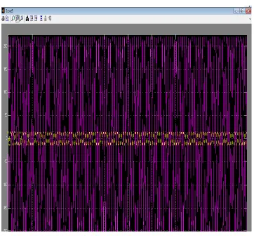
5. Performance Analysis Of Induction Motor 5.1 Waveform of Source Voltage and Current
Fig. 7: Waveform of source voltage and current.
In this proposed simulation diagram, the AC source voltage of 220 V and source current of
4.12A is applied and waveforms corresponding to this ratings are obtained and displayed.
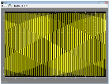
5.2 Waveforms of Phase Voltage and Line Current
Fig. 8: Waveform of phase voltage in volts.
The waveform of phase voltage of induction machine drive is shown in figure 8 and in this,
the phase voltage is given in volts and is measured in terms of time in seconds and figure 9
includes the diagram of line current of induction machine drive.
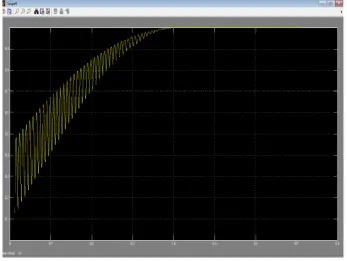
Fig. 10: Waveform power factor value.
Fig 10 shows the power factor rating when the source voltage and current is maintained at
220V and 4.02A respectively. It shows that the power factor is maintained 0.9532 in the input
side of the proposed drive. On comparing the existing and proposed model, the proposed
method i.e. the Flying capcitor Multi level inverter fed induction machine drive has ensured
the high power factor of about 0.95 which nearly a unity power factor and also improves the
performance of the system.
6. CONCLUSION
The project work has presented the Flying capacitor Multi level inverter to feed an Induction
machine drive. Initially, the important characteristics of induction machine was presented as
well as, its electric model necessary for the design of integrated topology. The proposed
circuit is designed for CCM operation, so that the inverter could be represented as an
equivalent resistance. A current sensor is used to measure the current in induction machine to
reduce the low power factor. The integration of two stages reduced the system size and cost.
A Flying capacitor Multi level inverter derived electricity issue correction topology for
induction machine the use of ANFIS good judgment controller has been supplied. The
advantages of this proposed gadget is less cost, one level of electricity conversion, easy
comments manipulate, and electricity issue is nearer to team spirit. The ANFIS good
conduction mode. By designing the converter to perform in continuous conduction mode, the
modern-day strain is sincerely much less and the life of the gadget may be advanced. On
comparing the existing and proposed model, the proposed method i.e. the Flying capacitor
Multi level inverter fed Induction machine drive has ensured the high power factor of about
0.95 which nearly a unity power factor and also improves the performance of the system. The
entire System was designed and implemented in MATLAB/SIMULINK. The performance of
the system for the extraordinary values of enter AC voltage has been evaluated and
discovered excellent.
REFERENCES
1. Sharkawi E l,Chen M A, Vandari S V, Fisser G W, Butter N G, Vinger R J, “An Adaptive
Power Factor Controller for Three Phase Induction Generator”, IEEE Transaction on
Power Apparatus and Systems, 1985; 104: 1825-1831.
2. J.Klein, M.K.Nalbant, “Power Factor Correction – Incentives,Standards and Techniques”,
PCIM Conf. proc., 1990; 26: 28-31
3. C.Nagarajan and M.Madheswaran, „Experimental verification and stability state space
analysis of CLL-T Series Parallel Resonant Converter with fuzzy controller‟ - Journal of
Electrical Engineering, 2012; 63(6): 365-372.
4. R.Raja and C.Nagarajan, “Performance Analysis of LCL-T Filter Based 2 Stage Single
Phase Gird Connected Module with ANN Controller using PV Panel," Current Signal
Transduction Therapy, 2018; 13(2): 159-167.
5. C.Nagarajan and M.Madheswaran, “Performance Analysis of LCL-T Resonant Converter
with Fuzzy/PID Using State Space Analysis” Springer, Electrical Engineering, 2011;
93(3): 167-178.
6. E.Geetha, C. Nagarajan, “Stochastic Rule Control Algorithm Based Enlistment of
Induction Motor Parameters Monitoring in IoT Applications," Wireless Personal
Communications, 2018; 102(4): 3629–3645.
7. M.Madheswaran, C.Nagarajan, “DSP Based Fuzzy Controller for Series Parallel
Resonant converter”, Frontiers of Electrical and Electronic Engineering, 2012; 7(4):
438-446.
8. C.Nagarajan, “Single-Stage High-Frequency Resonantac/AC Converter Using Fuzzy
Logic and Artificial Neural networks‟, Conference on Emerging Devices and Smart
Systems (ICEDSS), 2nd and 3rd March, organized by mahendra Engineering College,
9. E Geetha, C Nagarajan, “Induction Motor Fault Detection and Classification Using
Current Signature Analysis Technique”, Conference on Emerging Devices and Smart
Systems (ICEDSS), 2nd and 3rd March, organized by mahendra Engineering College,
Mallasamudram, 2018; 48-52.
10.GS SatheeshKumar, C Nagarajan, ST Selvi, “A Virtual Impedance Based Analysis of
Dynamic Stability in a Micro-Grid System”, Conference on Emerging Devices and Smart
Systems (ICEDSS), 2nd and 3rd March, organized by mahendra Engineering College,
Mallasamudram, 2018; 38-41.
11.CS Lakshmi, C Nagarajan, “Neural Controlled Multi-Level Inverter Based DVR for
Power Quality Improvement”, Conference on Emerging Devices and Smart Systems
(ICEDSS), 2nd and 3rd March, organized by mahendra Engineering College,
Mallasamudram, 2018; 42-47.
12.S Thirunavukkarasu, C Nagarajan, “Performance Analysis of BLDC Motor Drive for
Feed Drives”, ”, Conference on Emerging Devices and Smart Systems (ICEDSS), 2nd and
3rd March, organized by mahendra Engineering College, Mallasamudram, 2018; 67-70.
13.JP Daniel, C Nagarajan, “Hybrid Filter for Distorted Voltage Source in Microgrids”,
Conference on Emerging Devices and Smart Systems (ICEDSS), 2nd and 3rd March,
organized by mahendra Engineering College, Mallasamudram, 2018; 11-15.
14.K Umadevi, C Nagarajan, “High Gain Ratio Boost-Fly Back DC-DC Converter using
Capacitor Coupling”, Conference on Emerging Devices and Smart Systems (ICEDSS), 2nd
and 3rd March, organized by mahendra Engineering College, Mallasamudram, 2018;
64-66.
15.C.Nagarajan and M.Madheswaran, “Experimental Study and steady state stability
analysis of CLL-T Series Parallel Resonant Converter with Fuzzy controller using State
Space Analysis”, Iranian Journal of Electrical and Electronic Engineering, 2012; 8(3):
259-267.
16.Santhana Lakshmi and C. Nagarajan, “Multiconverter Technology Based Voltage
Compensation for Photovoltaic System” Ecology, Environment and Conservation, 2017;
17.C.Nagarajan and M.Madheswaran, ”Stability Analysis of Series Parallel Resonant
Converter with Fuzzy Logic Controller Using State Space Techniques”, Electric Power
Components and Systems, 2011; 39(8): 780-793.
18.C.Nagarajan, M.Muruganandam and D.Ramasubramanian – „Analysis and Design of
CLL Resonant Converter for Solar Panel - Battery systems- International Journal of
Intelligent systems and Applications, 2013; 5(1): 52-58.
19.C.Nagarajan and M.Madheswaran, “Experimental Study and Comparative Analysis of
CLL-T and LCL-T Series Parallel Resonant Converter with Fuzzy/ PID Controller”,
Journal of Electrical Engineering, 2011; 11(3): 122-129.
20.C.Nagarajan and M.Madheswaran “Analysis and Simulation of LCL Series Resonant Full
Bridge Converter Using PWM Technique with Load Independent Operation” has been
presented in ICTES‟08, a IEEE / IET International Conference organized by
M.G.R.University, Chennai, 2007; 1: 190-195.
21.Nagarajan, M.Madheswaran and D.Ramasubramanian, “Development of DSP based
Robust Control Method for General Resonant Converter Topologies using Transfer
Function Model,” Acta Electrotechnica et Informatica Journal, 2013; 13(2): 18-31.
22.S.Sathish Kumar and C.Nagarajan, “Performance - Economic and Energy Loss analysis
of 80 KWp Grid Connected Roof Top Transformer less Photovoltaic power Plant,”