Published online November 23, 2014 (http://www.sciencepublishinggroup.com/j/ijmea) doi: 10.11648/j.ijmea.s.2015030102.11
ISSN: 2330-023X (Print); ISSN: 2330-0248 (Online)
Vane geometry effect on lubrication conditions between
vane tip and cam-ring in hydraulic vane machines
Mohamed Elashmawy
1, 2, *, Abdulaziz Alghamdi
11
Mechanical Engineering Department, Engineering College, University of Hail, Hail, Saudi Arabia 2
Engineering Science Department, Faculty of Petroleum and Mining Engineering, Suez University, Suez, Egypt
Email address:
arafat_696@yahoo.com (M. Elashmawy), a.alghamdi@uoh.edu.sa (A. Alghamdi)
To cite this article:
Mohamed Elashmawy, Abdulaziz Alghamdi. Vane Geometry Effect on Lubrication Conditions between Vane Tip and Cam-Ring in Hydraulic Vane Machines. International Journal of Mechanical Engineering and Applications. Special Issue: Advanced Fluid Power Sciences and Technology. Vol. 3, No. 1-2, 2015, pp. 1-10. doi: 10.11648/j.ijmea.s.2015030102.11
Abstract:
Vane geometry is an important parameter affecting the lubrication conditions of hydraulic vane machines. A simple thermo-elasto-hydrodynamic lubrication (TEHL) model was used to calculate the friction between vane tip and cam-ring of the hydraulic vane machines. Effect of vane geometry and its dimensions on hydraulic vane machines was theoretically investigated. Navier-Stokes and energy equations were numerically solved using finite difference technique. Viscosity and density distributions were considered in the TEHL-model. Results show that vane geometry optimization is quite important to enhance lubrication conditions of hydraulic vane machines. The study shows that the straight vane geometry is the best choice for high pressure applications. At higher values, increasing of vane tip radius of curvature and vane thickness enhances lubrication conditions between vane tip and cam-ring. Vane tip radius of curvature and vane thickness should not be less than 2 mm and 1.5 mm respectively.Keywords: Vane Geometry, Friction Coefficient, TEHL-Model, Vane Tip Radius, Vane Thickness
1. Introduction
Friction forces between vane tip and cam-ring in hydraulic vane machines is essential parameter affecting its performance. Trying to understand the nature and behavior of this parameter is very important to minimize it. Decreasing vane tip friction enhances hydraulic vane machines performance which enhances its wear, life time and its fuel consumption. Many parameters affecting the hydraulic vane machines performance were studied by others. The following parameters were selected:
1.1. Oil Temperature
Thermo-elasto-hydrodynamic lubrication (TEHL) model was used. Navier- Stokes and energy equations were numerically solved using finite difference technique. The effect of operating oil temperature and oil film thickness on friction coefficient between van tip and cam-ring was studied for 3 different oil groups to predict the effect of oil type on van pump performance. Results show that increasing of oil film thickness alone does not guarantee the improvement of vane tip and cam-ring lubrication conditions. Operating oil
temperature strongly affects the friction coefficient. Increasing operating oil temperature increases coefficient of friction in the low temperature regions while decreases it at the high temperature regions. For vane pump that runs under different operating conditions, more than one oil type may be required to optimize its performance [1].
Temperature variation is taken into consideration for thermal TEHL models, however it fixed and taken equal to pump oil temperature in case of isothermal TEHL model. Results show that isothermal analysis is highly not recommended for the applications and parameters that depend on viscosity and/or velocity distributions [2]. Increasing oil temperature decreases friction forces and enhances vane pump efficiency in low temperature regions, however increasing oil temperature not decreases friction force in high temperature regions [3]. For balanced vane pumps the region of higher overall pump efficiency is at oil temperature around 80°C and decreases at extremely low and high oil temperatures [4].
1.2. Cam Surface Roughness and Vane Tip Coatings
roughness ratio [5]. Lessening cam contour surface roughness reduces friction torque, which improves pump mechanical efficiency [6].
A comparison study was performed between five different Physical Vapor Deposition (PVD) coated vane tips in addition to the traditional vane without coating. The effect of the radial vane force and the pressure difference between the two sides of the vane were found very small compared to other parameters such as vane relative speed. Coating material shows insignificant effect for the friction coefficient between vane tip and cam-ring in oil vane pumps [7].
1.3. Vane Geometry
For transfer pump lubricated with diesel fuel, increasing blade surface radius improves the lubricant film parameter and reduces the friction by 80 % [5].
A theoretical study using CAD and CFD modeling was performed for three different vane tip geometries, Fig. 1. Results show that the vane tip optimum geometry was found for a profile with radiused inlet and with NACA investigated profile in the outlet [8].
Figure 1. The three deferent vane tip geometries [4].
An experimental and theoretical study about the ratio of vane pump lift to vane thickness (ε) effect on vane tip friction torque was performed for balanced vane pumps. Results show that ε is an important parameter affecting the pump efficiency. Increasing of ε and reducing friction coefficient increases pump efficiency. Increasing ε increases the variation of the vane friction torque [9].
2. Vane Geometry Analysis
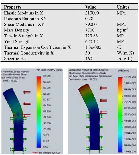
Vane geometry is an effective parameter of hydraulic vane machines. The common material used for the vane is DIN S-3-3-2. Common vane geometry is of straight shape. Fig. 2 shows a straight vane belongs to a balanced hydraulic vane machine that consists of 10 vanes. SolidWorks was used for 3D-CAD geometry and stress analysis. Table 1 tabulated vane material properties of steel alloy. Simulation-Xpress Analysis Wizard of SolidWorks software was used to simulate stress analysis and material deflection of all vane geometries used in this study.
Fig. 3 shows stress analysis and material deflection for straight vane geometry. Minimum factor of safety of 1.4 is used for all vane shapes under pressure of 200 bar (radial vane force was neglected for all vane geometries). The minimum vane thickness of straight vane geometry is 1.3 mm with maximum vane deflection of 12 µm.
Figure 2. Straight vane geometry for balanced hydraulic vane machine. Table 1. Vane Material Properties.
Property Value Unites
Elastic Modulus in X 210000 MPa Poisson's Ration in XY 0.28 -- Shear Modulus in XY 79000 MPa
Mass Density 7700 kg/m3
Tensile Strength in X 723.83 MPa Yield Strength 620.42 MPa Thermal Expansion Coefficient in X 1.3e-005 /K Thermal Conductivity in X 50 W/(m· K)
Specific Heat 460 J/(kg·K)
Figure 3. Stress analysis and material deflection of the straight vane
geometry for balanced vane machine.
Figure 4. Forward curved vane geometry for balanced hydraulic vane
machine.
Figure 5. Stress analysis and material deflectionof the forward curved vane geometry for balanced hydraulic vane machine.
Figure 6. Backward curved vane geometry for balanced hydraulic vane machine.
Fig. 6 shows balanced hydraulic vane machine of backward curved vane geometry.
Figure 7. Stress analysis and material deflection of the backward curved vane geometry for balanced hydraulic vane machine.
Fig. 7 shows that, for backward curved vane geometry, the minimum vane thickness of 3.0 mm with maximum vane deflection of 18.1 µm. Stress and deflection analysis shows that the best vane geometry is the straight vane shape.
3. TEHL-Model
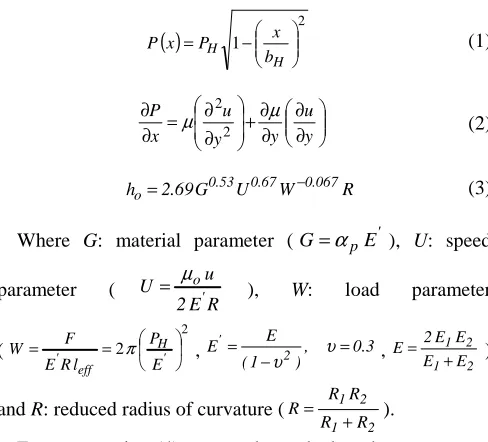
Vane tip smooth contact with cam-ring is simulated and modeled using thermo-elasto-hydrodynamic lubrication model, TEHL-model [2]. Pressure distribution is simply replaced by Hertzian distribution “elliptic curve” (1). Theoretical models solving Navier-Stoke's equation (2) with elastic deformation were used for TEHL-model. Contact geometry area was simplified by two parallel surfaces. Lubricant film thickness is calculated according to Hamrock-Dowson formula (3) [10].
( )
1 2 − = H H b x P x
P (1)
∂ ∂ ∂ ∂ + ∂ ∂ = ∂ ∂ y u y y u x P µ
µ 22 (2)
R W U G 69 . 2
ho= 0.53 0.67 −0.067 (3)
Where G: material parameter (G=αpE' ), U: speed
parameter (
R E 2 u U ' o µ
= ), W: load parameter
( 2 2 =
= H'
eff ' E P l R E F
W π , , 0.3
) 1 (
E
E' 2 =
−
= υ
υ , 1 2
2 1 E E E E 2 E + = )
and R: reduced radius of curvature (
2 1 2 1 R R R R R + = ).
Energy equation (4) was used to calculate the temperature distribution for lubricant oil film. Using specific heat of oil cp=2000 J/kgK. Conduction heat transfer coefficient for oil
was taken according to Rodermund (5).
0 2 2 2 = ∂ ∂ + ∂ ∂ + ∂ ∂ ∂ ∂ − ∂ ∂ + ∂ ∂ y u y T k x P T T u y T v x T u c _ p µ ρ ρ ρ (4)
With boundary conditions, T=To for x -∞
− + = − o o o P P P k
k 1 10 4 , ko=0.15 W/mK (5)
Viscosity variation (6) as a function of pressure and temperature was used. Table 1 (appendix1) shows the constants of (6) at low and high pressure regions. Two mineral oil types (FVA1 and FVA2) were used according to the classification of reference oil of the German research association of drives technology or in German Forschungsvereinigung Antriebstechnik (FVA) [11].
+ − + + + + + = C T C T P B P C T B K ln ln o T p p P , T o o o 1 1 ∆ ∆ α µ (6) With C T and P P C C o o atm o o 0 , ,
95 = =
=
Table 2 (appendix1) shows the constants of (7) at low and high pressure regions for the oil types used [11].
T
T
P
P
T
T bar P C po o P T o o
∆
∆
+
+
+
=
ρ
α
α
α
ρ
, , ,0 ,0 (7)4. Results and Discussion
the focus of this study. Vane tip radius of curvature and vane thickness effects on friction coefficient, oil temperature and oil film thickness were theoretically investigated using the TEHL-model for two mineral oil types (FVA1 and FVA2) at different vane speeds, temperatures and pressures.
4.1. Effect of Vane Tip Radius on Friction Coefficient
Vane tip radius of curvature is quite important parameter that should be designed with great attention.
Figure 8. Effect of vane tip radius of curvature on friction coefficient for
FVA1 mineral oil at 1.5 mm vane thickness, 60 oC and 150 bar.
Fig. 8 shows the effect of vane tip radius of curvature on friction coefficient for FVA1 mineral oil at 1.5 mm vane thickness, 60 oC and 150 bar operating temperature and pressure respectively. Curves show that radius of curvature has significant effect on the friction coefficient between vane tip and cam-ring. Increasing radius of curvature increases friction coefficient at low values of radius (almost 2 mm) for low vane speeds, while it decreases at higher radius values for all vane speeds. The effect of radius of curvature on friction coefficient is significant at low vane speeds. The radius effect significantly decreases by increasing vane speed. This behave indicates that vane speed is a key parameter for hydraulic vane machines. The speed higher than 5000 rpm is recommended. For low speed hydraulic vane machines, great attention of vane tip geometry is quite important for good lubrication conditions and low energy consumption.
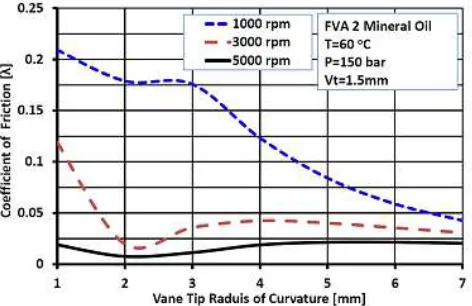
Figure 9. Effect of vane tip radius of curvature on friction coefficient for
FVA2 mineral oil at 1.5 mm vane thickness, 60 oC and 150 bar.
Fig. 9 shows the effect of vane tip radius of curvature on friction coefficient for FVA2 mineral oil at 1.5 mm vane thickness, 60 oC and 150 bar operating temperature and pressure respectively. Comparing curves of Fig. 9 with Fig. 8 shows that the curves at low vane tip radius of curvature (below 2 mm) have different behaves (sometimes behave inversely). But both oil types have the same behavior at higher vane tip radius of curvatures. This shows the importance of proper oil type selection beside physical properties of machine geometry.
Figure 10. Effect of vane tip radius of curvature on friction coefficient for
FVA1 mineral oil at 1.5 mm vane thickness, 60 oC and 3500 rpm.
Fig. 10 shows the effect of vane tip radius of curvature on friction coefficient for FVA1 mineral oil at 1.5 mm vane thickness, 60 oC operating temperature, 3500 rpm. Curves show that increasing operating pressure shifts the peak of curves to the right side. Increasing operating pressure increases the minimum accepted vane tip radius of curvature that starts to decrease the friction coefficient between vane tip and cam-ring. Curves show that the minimum value of vane tip radius of curvature should not be less than 3 mm for good lubrication conditions between vane tip and came ring.
Figure 11. Effect of vane tip radius of curvature on friction coefficient for
FVA2 mineral oil at 1.5 mm vane thickness, 60 oC and 3500 rpm.
should not be less than 3 mm for good lubrication conditions.
4.2. Effect of Vane Tip Radius on Oil Film Thickness
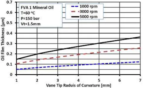
Fig. 12 shows the effect of vane tip radius of curvature on oil film thickness for FVA1 mineral oil at 1.5 mm vane thickness, 60 oC and 150 bar for three different speeds. Curves show that increasing of vane tip radius enhances oil film thickness. Oil film thickness enhancement increases significantly by increasing of vane speed. Effect of vane tip radius is almost similar to effect of vane speed.
Figure 12. Effect of vane tip radius of curvature on oil film thickness for FVA1
mineral oil at 1.5 mm vane thickness, 60 oC and 150 bar.
Figure 13. Effect of vane tip radius of curvature on oil film thickness for FVA2
mineral oil at 1.5 mm vane thickness, 60 oC and 150 bar.
Fig. 13 shows the effect of vane tip radius of curvature on oil film thickness for FVA2 mineral oil at 1.5 mm vane thickness, 60 oC and 150 bar for three different vane speeds. Curves show that increasing of vane speed affects the FVA2 oil film thickness much more than FVA1 oil type. Oil properties plays great rule on hydraulic vane machines performance. Fig. 14 shows the effect of vane tip radius of curvature on oil film thickness for FVA1 mineral oil at 1.5 mm vane thickness, 60 oC and 3500 rpm for three different operating pressures. Curves show that increasing of vane tip radius of curvature significantly enhances oil film thickness. Increases of operating pressure have negative impact on oil film thickness. It should be mentioned that the TEHL-model is designed only to deal with oil film between vane tip and cam-ring assuming that came ring as a circular contour.
Increasing operating pressure significantly would result in significant deviation because of mixed friction which is not included in the model. The results drawn from this theoretical study is considered as primary results and need more investigation for accurate results.
Figure 14. Effect of vane tip radius of curvature on oil film thickness for FVA1
mineral oil at 1.5 mm vane thickness, 60 oC and 3500 rpm.
Figure 15. Effect of vane tip radius of curvature on oil film thickness for FVA2
mineral oil at 1.5 mm vane thickness, 60 oC and 3500 rpm.
Fig. 15 shows the effect of vane tip radius of curvature on oil film thickness for FVA2 mineral oil at 1.5 mm vane thickness, 60 oC and 3500 rpm for three different operating pressures. Curves show that FVA2 oil type has significant oil film thickness than FVA1 oil group. While FVA1 has better friction coefficient behavior than FVA2 group as shown in Fig. 10 and Fig. 11. Increasing oil film thickness not necessarily enhances lubrication conditions.
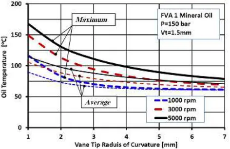
4.3. Effect of Vane Tip Radius on Oil Film Temperature
decreases both of maximum and average oil temperature within contact area. Increasing vane speed also increases oil maximum and average temperatures.
Figure 16. Effect of vane tip radius of curvature on oil film temperature for
FVA1 mineral oil at 1.5 mm vane thickness, and 150 bar.
Figure 17. Effect of vane tip radius of curvature on oil film temperature for
FVA1 mineral oil at 1.5 mm vane thickness, and 3500 rpm.
Figure 18. Effect of vane tip radius of curvature on oil film temperature for
FVA2 mineral oil at 1.5 mm vane thickness, and 150 bar.
Fig. 17 shows the effect of vane tip radius of curvature on oil maximum and average temperatures for FVA1 mineral oil at 1.5 mm vane thickness, and 3500 rpm at three different operating pressure values. Curves show that increasing operating pressure increases oil maximum and average temperatures. General effect of operating pressure on oil
temperature has the same effect of vane speed.
Fig. 18 shows the effect of vane tip radius of curvature on oil maximum and average temperatures for FVA2 mineral oil at 1.5 mm vane thickness, and 150 bar at three different vane speeds. FVA2 has higher temperatures than FVA1 which gives little advantage for FVA1 oil group.
Figure 19. Effect of vane tip radius on oil film temperature for FVA2 mineral
oil at 1.5 mm vane thickness, and 3500 rpm.
Fig. 19 shows the effect of vane tip radius of curvature on oil maximum and average temperatures for FVA2 mineral oil at 1.5 mm vane thickness, and 3500 rpm at three different operating pressure values. Increasing operating pressure increases oil temperature at vane tip contact area.
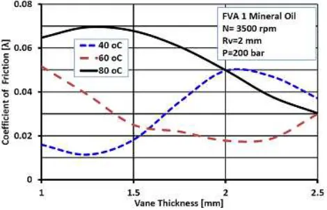
4.4. Effect of Vane Thickness on Friction Coefficient
Vane thickness is an important parameter for vane hydraulic machines. Increasing of vane thickness would result on an increase of applied radial force on vane tip.
Figure 20. Effect of vane thickness on vane tip friction coefficient for FVA1
mineral oil at 2 mm vane tip radius, 3500 rpm and 100 bar.
decreases vane tip friction coefficient at low temperatures while increases it at higher temperatures. Increasing operating pressure from 100 bar to 200 bar leads the peak of all curves to be shifted toward the right side, Fig. 21. Both curves of Fig. 20 and Fig. 21 show that vane thickness should be higher than 1.5 mm to satisfy low vane tip friction coefficient.
Figure 21. Effect of vane thickness on vane tip friction coefficient for FVA1
mineral oil at 2 mm vane tip radius, 3500 rpm and 200 bar.
Figure 22. Effect of vane thickness on vane tip friction coefficient for FVA2
mineral oil at 2 mm vane tip radius, 3500 rpm and 100 bar.
Figure 23. Effect of vane thickness on vane tip friction coefficient for FVA2
mineral oil at 2 mm vane tip radius, 3500 rpm and 200 bar.
Fig. 22 shows the effect of vane thickness on vane tip friction coefficient for FVA2 mineral oil group at 2 mm vane tip radius, 3500 rpm and 100 bar for 40, 60 and 80 oC operating
temperatures. Curves show that vane tip friction coefficients are significantly high in the region below vane thickness value of 1.5 mm especially at higher operating temperatures.
Fig. 23 shows that increasing operating pressure slightly increases the general value of friction coefficient. The curve of FVA2 oil group at low operating temperature (40 oC) shows dramatic increase of vane tip friction coefficient by increasing of vane thickness.
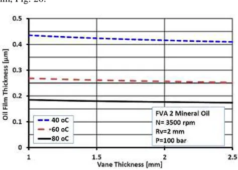
4.5. Effect of Vane Thickness on Oil Film Thickness
Oil film thickness is a sensitive parameter that greatly depends on oil type, oil properties, operating conditions, and machine geometry.
Figure 24. Effect of vane thickness on oil film thickness for FVA1 mineral oil
at 2 mm vane tip radius, 3500 rpm and 100 bar.
Fig. 24 shows the effect of vane thickness on oil film thickness for FVA1 oil group at 2 mm vane tip radius, 3500 rpm vane speed and 100 bar operating pressure. Curves of Fig. 24 show that oil film decreases by increasing vane thickness.
Figure 25. Effect of vane thickness on oil film thickness for FVA1 mineral oil
at 2 mm vane tip radius, 3500 rpm and 200 bar.
mm, Fig. 20.
Figure 26. Effect of vane thickness on oil film thickness for FVA2 mineral oil
at 2 mm vane tip radius, 3500 rpm and 100 bar.
Fig. 26 shows the effect of vane thickness on oil film thickness for FVA2 oil group at 2 mm vane tip radius, 3500 rpm vane speed and 100 bar operating pressure. Curves of Fig. 26 show that the oil film decreases by increasing of vane thickness. Increasing of operating temperature significantly decreases oil film thickness. Increasing operating pressure decreases oil film thickness, Fig. 27.
Figure 27. Effect of vane thickness on oil film thickness for FVA2 mineral oil
at 2 mm vane tip radius, 3500 rpm and 200 bar.
4.6. Effect of Vane Thickness on Radial Vane Force
Vane thickness effect on radial vane force has a linear behave. At constant vane width (16 mm) increasing of vane thickness would result of an increase of vane area subjected to machine operating pressure which increases radial vane force linearly. Increasing radial vane force increases vane tip cam-ring tightness which decreases oil leakage between them. At the same time it may cause negative influence on friction coefficient of vane tip sliding contact with cam-ring.
Fig. 28 shows the linear curves of vane radial force as a function of vane thickness at 100 bar and 200 bar operating pressures. Increasing of operating pressure magnifies the effect of vane thickness on vane radial force.
Figure 28. Effect of vane thickness on vane radial force at 100 bar and 200
bar operating pressures.
4.7. Effect of Vane Thickness on Vane Tip Deformation Length of Elasto-Hydrodynamic Deformation
Elasto-hydrodynamic deformation due to very high pressure of lubricant between vane tip and cam-ring within contact area was modeled according to Hertzian distribution “elliptic curve” (1). Fig. 29 shows the effect of vane thickness on vane tip elasto-hydrodynamic deformation length at 100 bar and 200 bar operating pressures. Curves of Fig. 29 show that increasing of vane thickness increases vane tip elasto-hydrodynamic deformation length. Increasing of the operating pressure causes the curve to be shifted upward and increases all values of vane tip deformation length.
Figure 29. Effect of vane thickness on vane tip elasto-hydrodynamic
deformation length at 100 bar and 200 bar operating pressures.
5. Conclusions
This study concentrates on vane geometry effect on oil van machines performance. TEHL-model developed by Elashmawy [2] was used for theoretical parametric study of vane geometry and its impact on vane tip friction coefficient, oil film thickness, maximum and average oil film temperatures. The study was performed for two different mineral oil type groups, FVA1 and FVA2 according to the German research association of drives technology [11].
cam-ring. Vane tip radius of curvature should not be less than 2 mm and recommended to be higher than 3 mm. Effect of increasing vane tip radius of curvature is similar to the effect of increasing vane speed. Both enhance lubrication conditions after some certain values (2 mm and 1000 rpm).
Increasing vane thickness causes an increase of radial vane force and as a result oil film thickness decreases. In general increasing vane thickness decreases vane tip friction coefficient at low temperatures while increases it at higher temperatures. 1.5 mm vane thick or higher is recommended.
Straight vane design is the best choice for high operating pressures applications. SolidWorks was used for 3D-CAD geometry and stress analysis. Steel alloy was selected for comparison between three vane geometries (straight, forward and backward curved). Simulation-Xpress Analysis Wizard of SolidWorks was used to simulate stress analysis and material deflection of the three selected vane geometries. Operating pressure of 200 bar and factor of safety of 1.4 were selected as a base of comparison. The minimum vane thickness of straight vane geometry was 1.3 mm with maximum vane deflection of 12 µm. While the minimum vane thickness value of 2.4 mm and 3.0 mm with maximum vane deflection of 18.5 µm and 18.1 µm were obtained for forward and backward curved vane geometries respectively at the same factor of safety (1.4).
Nomenclature
bH Hertzian deformation length [µ m]
E Modulus of elasticity [Pa]
G Material parameter [--]
ho Mean film thickness [µ m]
k Thermal conductivity [W/mK]
ko Thermal conductivity at atmosphere [W/mK]
leff Effective contact length, vane width [m]
P System pressure [bar]
PH Hertzian pressure [bar]
R Reduced radius of curvature [--]
RV Vane tip radius of curvature [mm]
T Oil temperature [oC]
To Oil initial temperature [oC]
U Speed parameter [--]
u Oil velocity component, x-axis [m/s]
v Oil velocity component, y-axis [m/s]
W Load parameter [--]
Greek Symbols
λ Friction coefficient [--]
µ Dynamic viscosity [Pa.s]
υ Poisson’s ratio, 0.3 for steel [--]
ρ Density [kg/m3]
τ Shear stress [N/m2]
Appendix 1
Tables of Data Used for TEHL-Model
Table 1. Constants of (6) at low and high pressures for the used oil groups [11]
Pressure Range KPo[cp] BPo[
oC]
o
T
α [10-3/bar]
P / B ∆
∆ [oC/bar] Errror [%]
11: FVA1 (p≤103) 0.15330 621.53 2.6320 0.26817 -- 11: FVA1 (p>103) 0.0914 711.90 2.3609 0.26372 10.43
28: FVA2 (p≤103) 0.14393 754.49 3.0051 0.33613 1.150 28: FVA2 (p>103) 0.2397 720.79 2.8206 0.32838 4.55
Table 2. Constants of (7) at low and high pressures for the used oil groups [11]
Pressure Range ρo,o αTo,0bar [10
-4]
C , P0o
α [10-5]
T /
p ∆
α
∆ [10-7]
Error [%]
11: FVA1 (p≤103) 0.87008 -6.4323 4.2719 1.1670 0.228 11: FVA1 (p>103) 0.8837 -5.2660 2.7814 4.1137 1.12 28: FVA2 (p≤103) 0.88310 -5.5440 4.2565 1.1010 0.246 28: FVA2 (p>103) 0.8986 -5.7675 2.3967 0.984 1.13
References
[1] Mohamed Elashmawy. Theoretical Investigation of Friction Forces between Vane Tip and Cam-Ring in Oil Vane Pumps.
International Journal of Science, Technology and Society. Vol.
2, No. 5, 2014, pp. 121-128. doi: 10.11648/j.ijsts.20140205.15 [2] M. Elashmawy. Study of Vane Tip Friction in Oil Vane pump.
Suez Canal University Dissertation. Egypt, 2009.
[3] Y. Inaguma. Oil temperature influence on friction torque characteristics in hydraulic pumps. Proc IMechE Part C: J
Mechanical Engineering Science 226(9); pp. 2267-2280, 2011.
[4] Y. Inaguma and N. Yoshida. Mathematical Analysis of Influence of Oil Temperature on Efficiencies in Hydraulic Pumps for Automatic Transmissions. SAE Int. J. Passeng. Cars
- Mech. Syst. 6(2):786-797, doi:10.4271/2013-01-0820, 2013.
[5] P. C. Sui. Prediction of film thickness and friction at a rotary pump blade and liner interface. American Society of
Mechanical Engineering (ASME). Vol. 72, ASME, New York,
[6] Y. Inaguma, and A. Hibi. Reduction of friction torque in vane pump by smoothing cam ring surface. Proceedings of the
Institution of Mechanical Engineers Part C-Journal of Mechanical Engineering Science. 221 (5), pp. 527-534, 2007.
[7] M. Elashmawy, and H. Murrenhoff. Experimental Investigation of friction force between vane tip and cam-ring in oil vane pumps. International Journal of Fluid Power. Vol. 10, No. 1, pp 37-46, 2009.
[8] M. Panek. Vane pump control in order to maintain liquid friction and leak tightness. International Capathian Conference
ICCC. Zakopane, Poland, 2004.
[9] Y. Inaguma, and N. Yoshida. Variation in Driving Torque and Vane Friction Torque in a Balanced Vane Pump. SAE Technical
Paper, 2014-01-1764, 2014.
[10] P. W. Gold. Tribology. Umdruck zur Vorlesung.
Trans-Aix-Press, Aachen, Germany, 2003.
![Table 1. Constants of (6) at low and high pressures for the used oil groups [11]](https://thumb-us.123doks.com/thumbv2/123dok_us/8462303.1708810/9.595.41.552.467.538/table-constants-low-high-pressures-used-oil-groups.webp)
