magnetic field lines, are investigated in the Large Helical Device (LHD) using short pulse injections of neutral beams (NB). Fast-ion lifetimes are evaluated using the fast neutral decay times after NB turn-off, where the neutrals are measured by an array of silicon-diode fast neutral analyzers. We found that the lifetime normalized by the 90-degree pitch-angle scattering time can be used as a scale of fast-ion confinement properties in magnetically confined fusion devices. The good confinement properties of the LHD’s inwardly shifted configuration were demonstrated using the evaluated normalized lifetimes.
c
2010 The Japan Society of Plasma Science and Nuclear Fusion Research
Keywords: fast-ion confinement, heliotron device, trapped particle, NB-blip, fast neutral measurement DOI: 10.1585/pfr.5.S2042
1. Introduction
Achieving good confinement properties of fast ions is one of the most important concerns in magnetically con-fined fusion devices, since it is necessary to sustain plas-mas by fusion-born alpha particles to realize fusion reac-tors. In stellarator devices, where the confining magnetic field is provided only by magnetic coils, the heating effi -ciency of fusion-born alpha particles might be degraded, since the three-dimensional (3D) ripple components of magnetic field lines strongly affect the orbit topologies of fast ions. Therefore, investigating fast-ion confinement properties with 3D ripple components is important in heli-cal devices. Moreover, the effect of 3D ripple components on fast-ion confinement has recently been recognized to be important in tokamak devices as well, since these com-ponents might be enhanced with the introduction of test blanket modules (TBMs) and/or resonant magnetic pertur-bation (RMP) coils in the International Thermonuclear Ex-perimental Reactor (ITER) [1, 2].
A radial neutral beam (NB) has been in operation on the Large Helical Device (LHD) since 2005. All the fast ions produced by the NB have kinetic energies largely per-pendicular to the magnetic field lines. The confinement properties of perpendicular particles strongly depend on the ripple structures of the magnetic configuration. There-fore, the particles produced by the radial NB can be used as test particles to investigate the confinement properties of fast ions in various configurations of the LHD.
author’s e-mail: [email protected]
This paper presents the results of short-pulse NB in-jection (NB-blip) experiments using the radial NB. The confinement properties of perpendicular fast ions are in-vestigated by measuring the decay time of fast neutrals after the NB turn-off. These fast neutrals are measured by a radial array of silicon diodes [3, 4], which have sight lines perpendicular to the magnetic field lines of the LHD. The experimental apparatus is described in section 2. The experimental results are shown and fast-ion confine-ment properties are discussed in section 3, while section 4 presents the conclusion.
2. Experimental Apparatus
Figure 1 shows a schematic drawing of the LHD mid-plane and radial NB injection (NBI). The center line of the injector is set perpendicular to the axis of LHD plas-mas in a cross section in which the plasplas-mas are horizon-tally elongated, and is placed on the midplane of the LHD. An injection energy of 40 keV is chosen for a beam com-posed of hydrogen ion species, and the total nominal in-jection power of the NBI is 6 MW. The NBI has four ion sources, which are aligned both horizontally and verti-cally. The locations of the ion sources are identified as UA, LA, UB, and LB, which indicate the upper-left, lower-left, upper-right, and lower-right locations, respectively. The axis of each ion source is tilted 2.76 deg. horizontally and 3.45 deg. vertically. Both the focal points and the pivot point are set to a point atR=4.9 m on the midplane, and the distance from the ion sources to the point is 8.3 m. A
c
2010 The Japan Society of Plasma
Fig. 1 Schematic drawing of cross-sectional view of the LHD midplane and radial NB injection geometry. Hatched area shows the cross section of the LHD standard configura-tion.
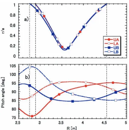
Fig. 2 (a) Normalized minor radii and (b) pitch-angle distribu-tions along the center lines of ion sources of radial NBI in theσ-optimized (Rax =3.6 m) configuration. Black
dashed lines indicate the location of the last closed flux surface.
typical divergent angle of the beam is 1.2 deg. In Fig. 2, the normalized minor radii distribution and pitch-angle distri-bution along the center lines are shown for the LHD σ-optimized configuration (Rax=3.6 m), where good particle transport is expected theoretically in stellarators [3]. Rax denotes the major radius of the configuration’s magnetic
Fig. 3 (a) Normalized minor radii and (b) pitch-angle distribu-tions along the sight lines of the Si-FNAs. Their sight lines are located atR=3.3 m (#1), 3.6 m (#2), and 3.9 m (#3).
axis.
To investigate the confinement properties of perpen-dicular fast ions in the plasmas, fast neutrals produced by charge exchange between fast ions and neutrals in plasmas are measured by a fan array of fast neutral analyzers based on silicon diodes (Si-FNAs) [2, 3]. The array is installed at the lower port of the LHD; its port location is indicated by an X in Fig. 1. Three of the Si-FNAs in the array are used for the analysis described here. Their sight lines are shown with the distributions of normalized minor radii and pitch angles in Fig. 3. The solid angles of their sight lines are 2.7×10⁻⁵sr at the maximum and can be reduced to 8.1×10⁻⁶sr. In Fig. 1, a typical orbit of a deeply trapped particle, which is produced by the radial NB and can be measured by one of the Si-FNAs (#3), is shown by a blue curve. No active sources of neutrals for charge exchange processes, i.e., pellets and/or NBs, are supplied for this di-agnostic procedure. Only the neutrals penetrating from the plasma’s periphery are used for this purpose. Thus, the measurement becomes line integrated along the sight lines of the FNAs. The Si diodes are cooled to−15◦C by a pair of Peltier modules to reduce thermal noise. The minimum energy ranges of the Si-FNAs are around 29 keV, and the energy resolutions are 5 keV at full width at half maximum. Both energies are limited by the amount of thermal noise. The upper limit of the measurable energy range is 1 MeV, which is determined by the input range of the analog-to-digital converters.
3. Evaluation of Perpendicular Fast
Ions with NB-blip Experiments
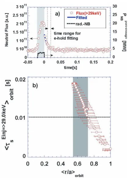
Fig. 4 (a) Typical waveform of fast neutral flux (open circles) and that of port-through power of the radial NB (dashed curves). Neutral flux measured by Si-FNA#3 and greater than 29 keV is shown. (b) Orbit-averaged slowing-down time distribution on the sight lines of Si-FNA#3. Dashed lines indicate a slowing-down time of 10 ms. Gray area indicates the region where the slowing-down time is longer than 10 ms.
short-pulse injection of the radial NB. A typical time trace of the perpendicular fast neutrals is shown in Fig. 4 (a). Signals of Si-FNA#3 greater than 29 keV are integrated, and those for eight NB pulses of 20 ms injection with plas-mas at almost the same density and temperature are accu-mulated in the figure. Figure 4 (b) shows the slowing-down time distribution on the sight line of Si-FNA#3. The sym-bol< >orbitdenotes an average value over the fast ion or-bit, and error bars indicate the width of the orbit. For the sight line of Si-FNA#3, the inner most observable region is<r/a>orbit=0.55, as shown in Fig. 3 (b). The slowing-down time from the NB injection energy, which is 36 keV for this particular case, to 29 keV is calculated according to the following formula and averaged along the orbits on the detector sight line:
τEinj→Ethres.
s = τse 3 ln ⎛ ⎜⎜⎜⎜⎜ ⎜⎝ E
3/2 inj.+E
3/2 c
E3thres/2.+E3c/2 ⎞ ⎟⎟⎟⎟⎟
⎟⎠, (1)
whereτse is the Spitzer slowing-down time and is calcu-lated from the electron densities and temperatures mea-sured by Thomson-scattering measurements and far in-frared (FIR) interferometers. Ec is the critical energy at which the heating rate of fast ions to bulk electrons and that
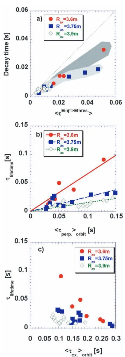
and 20 ms after NB turn-off. In Fig. 4 (a), the decay time of the neutral flux intensities is evaluated by exponential fitting of the data points betweent=0.01 and 0.02 s. The result of the fitting is shown by blue lines in the figure. The evaluated decay times are compared with the averaged slowing-down time in the region between<r/a>orbit=0.55 and 0.72 in Fig. 5 (a). In calculating the average, the weight ofw(r/a) as shown below is used:
w(r/a)= neτseorbitn0
dL(neτseorbitn0)
, (2)
where the integration in the denominator is done along the detector sight line. n0(r/a) is the neutral density calcu-lated by the AURORA code, and the product ofne(r/a) and <τse>orbitroughly represents the density profile of fast ions created by NB deposition on the sight line of the Si-FNA. Thus, the weight roughly expresses the fast neutral density profile along the sight line. The dashed line in Fig. 5 shows the line of a unity slope. The deviations of data points from this line indicate the amount of fast ion loss from the orbits on the Si-FNA sight line. In Fig. 5 (a), the deviation of data points is less significant for theRax =3.6 m configuration than for that ofRax = 3.75 m. This indicates better con-finement properties for theRax =3.6 m configuration and is consistent with a theoretical prediction of better confine-ment properties for the inwardly shifted configuration of the LHD [4]. The lifetimes of fast ions staying in their orbits can be evaluated by
1/τlifetime=1/τdecay−1/ τEinj.→Ethres. s
orbit. (3)
Fig. 5 Comparison of (a) orbit-averaged slowing-down times to decay times of neutral flux, (b) evaluated lifetimes to orbit-averaged 90-degree pitch-angle scattering times, and (c) charge exchange loss times. Red closed circles, blue closed squares, and green open diamonds represent the experimental results for theRax=3.6 m, 3.75 m, and
3.9 m configurations, respectively, atBt=2.5 T.
be the dominant loss process of fast ions from orbits on the detector sight line. Considering the magnitudes of the solid angles of the Si-FNA sight lines, which are of the order of
Fig. 6 Configuration dependence of normalized lifetime distri-butions.
10−5sr, as shown in section 2, the lifetimes evaluated from the flux decay times are much larger than the expected loss times with a simple pitch-angle scattering process from the sight line. From the particle balance of fast ions on the Si-FNA sight lines in velocity space, the fast-ion lifetime on the FNA sight line can be written as
dNLOS
dt =− NLOS τlifetime =
aNoutsice τperp. −
bNLOS
τperp. , (4) whereNLOSandNoutside are the number of particles inside and outside the solid angles of the sight lines in velocity space, respectively. The constantsaandbare determined from the observation geometries. Using this equation, the lifetime normalized by the 90-degree pitch-angle scatter-ing time can be written as
τlifetime/τperp.= b−1aγ, (5)
whereγ = Noutside/NLOS. If the fast-ion confinement is good,γis large, since the Si-FNA sight line observes close to the birth points of perpendicular fast ions in velocity space. Therefore, the normalized lifetime, which is evalu-ated from the slopes of data points for each configuration in Fig. 5 (b), can be considered a good indicator of fast-ion confinement properties.