DEVELOPMENT OF L4 & L5 SPINAL VERTEBRALIFEA MODEL USING IMAGE
PROCESSING TECHNIQUES
Nachiket S Kulkarni*
1*M.Tech. CAD/CAM (SMBS) Vellore Institute of Technology, Chennai CampusChennai, India
*Correspondence Author:[email protected] Keywords: component; formatting; style; styling; insert.
Abstract
In this new era of technology the fields of biology and engineering walk hand in hand. The finite element (popularly known as FE) tool is used here to analyze the lumbar vertebra L4 and L5. It is important to know the results of these vertebrae in case of healthy, abnormal and in generated case. The spine model was developed in MIMIC software from the computer topography (CT) data available. The model was analyzed in ANSYS and different results were observed which might be used in later studies of spinal cord. Stress distribution was also plotted and the results are plotted on the graph for the displacement of the vertebra under loading condition. The sole aim of this study is to find out the loading and stresses occurred on spinous process so that an alternative mechanical component with similar material properties will be developed.
.
Introduction
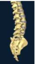
The image processing technique is a technique in which the output is in the form of a photograph or a video whose input is an image itself.There is need of more realistic model of the spine. The image processing technique can model a spine very close to the real spine using the CT scan data available to us. The Spine is a mechanical structure. The vertebrae articulate with each other in a controlled manner through a complex of levers (vertebrae), pivots (facets and discs), passive restraints (ligaments) and activations (muscles). The long, slender, ligamentous bony structure is markedly stiffened by the rib cage [1]. The spinal co lumn is the main load bearer of human musculoskeletal system. Here, in this paper, we will focus on the Lumbar spine (only L4 and L5 spinal vertebra). The geometry, mechanism and the issues related to the L4 and L5 spinal vertebra will be discussed in details. The stress analysis results of these done in ANSYS will also be discussed.
Literature
To perform the image processing and analyzing the Lumbar spine vertebra (L4 and L5) we need to go through the detailed information of the biomechanics, geometry and the issues related to the same.
Biomechanics
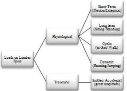
Application of mechanical principles to living organisms helps us to understand how all the bony and soft spinal components contribute individually and together to ensure spinal stability, and how traumas, tumors and degenerative disorders exert destabilizing effects. Spine stability is the basic requirement to protect nervous structures and prevent the early mechanical deterioration of spinal components.
The general load types according to the origin of the load are – 1. Gravity loads (standing upright)
When a person stands upright, that is, straight without bending the weight of the upper body is directly on the lower lumbar spine (mostly on L4 and L5). These loads get multiplied in acceleration, during fall, or other affects with acceleration or deceleration.
2. Muscle loads (depends on muscle activity)
Muscles are the active tissues in the human body. They can contract and their ability contraction is governed by the nervous system. The back and abdomen muscles prevent spine from extreme movements.
While standingor sitting erect compressive load from the muscles is double concerning the load of body weight. While bending forward with lifting load back muscle generates high tensile forces to equlibrate effects of vertically acting upper body load and lifted weight together. The effect of this large tensile force in the back muscles of lumbar spine generates high compression forces. Main components of the lumbar spine
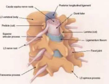
Figure 2 A typical lumbar vertebra consisting of Vertebral Body, Intervertebral Disc, Facet Joints, Ligaments, Spinous Process, Transverse Process, Inferior Articular Process, Superior Articular Process,etc.
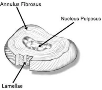
Intervertebral disc
It is a bulky structure. Intervertebral disc can be compared with a car tyre. As it bulges outwords when any compression force acts on it. It contains fluid inside it. The fluid contain reduces as the age of the human increases. Hence the disc related problems occur at older age. The disc has both tension and compression resisting property. The disc behaves as a ligament allowing for and controlling the complex 3D movements of spine-
1. Vertical Compression and Distraction 2. Flexion and Extension
Figure 3. General Schematics of Intervertebral Disc
The outermost annulus fibrosus are the first to control the abnormal micro-level movements of normal disc. Nucleus behaves like a pressured cylinder. Intervertebral disc is the main shock absorber of mechanical stresses. The central part of the disc is called nucleus puplosusand the peripheral one is called annulus fibrosus, they both are merging into each other as shown in figure 3. The disc fibers stretch to their physiological length and recoils when excess force is released. If the force exceeds physiological limit, amino acid chain, present, breaks and there will not be any recoil. In young humans disc is gel like which is incompressible but deformable, disc has approximately 80% water, which is designed to conduct and tolerate pressure. With age it desiccates and water contain is lost.
The figure 4 shows that wherever there is maximum overlapping of trabeculae, it refers to the zone of maximum resistance.The triangular area anteriorly where there are only vertical lines refers to the zone of minimum resistance where the risk o f failure by compression is maximum. Vertical load initially accepted by vertical trabecular system whose bowing is restrained by horizont al lamellae tension. Resistance of spongy bone depends upon mineral bone density.Facet joints have the main two functions (1) control of direction and amplitude of movement and (2) sharing of loads. The posterior facets accepts 0-33 % of loads depending on posture of the spinal cord. It is sometimes up to 70 %. Generally 15-40 % of chronic back pain is caused by the L4-L5 facet joints.
Figure 5.Anatomy of the Lumbar Vertebra
Ligaments are the passive stabilizers of the spine. Stabilization of a ligament depends on the intrinsic strength and the length of lever arm through which it acts. Very strong ligament is the one with short lever arm with less stability than the weak ligament with long lever arm which the mechanical advantage. There are total 7 types of ligaments, 5 connecting several parts of posterior elements and 2 connecting vertebral body itself. Ligament flavum (LF) is the most elastic ligament which connects the lower and upper ends of the interior surfaces of adjacent lamalae.
Normal spinal motion
The lumbar vertebra can perform three translational and three rotational along X, Y and Z Cartesian axis of space. According to Louis, during flexion-extension vertebra moves around transverse rotation axis placed not in the subjacent disc but the vertebra l body below. Both the endplates and facet joints perform two circumferential arcs around the same rotation centre as above, whose location changes with respect to the level. Low position of rotation centre is called antelisthesis (‘ante’ Latin word means front and ‘listhesis’ Greek word means sliding down on a slippery path). It is maximum (2-3 mm) at C2-C3 and minimum (0.5-1.5 at D1-L5). Axial rotation and lateral bending are always coupled movements because of the oblique orientation of both facet joints and muscles. The key for proper spinal function is highly non linear load to displacement ratio of function spine unit (FSU) because efforts are needed for movement changes significantly in various phases.
Range of motion
It is the physiological range of motion which includes neutral zone (NZ) and elastic zone (EZ).
Figure 6.Range of Motion (ROM).NZ-initial intervertebral motion with low resistance with high flexibility. EZ- followed by NZ has resistcne to movement and slope of curve increases linearly. Here ligaments, capsules, fascias and tendons are subjected to tension with more load per
Internal forces on lumbar spine
The compressive normal force is perpendicular to middle plane of discs causing high compression in disc. Accompnied by the sagital and less lateral shear forces in the middle plane of the disc. A compressive force arisen from body weight depends on weight of trunk, head and arms together.
While standing upright the vertical load is 55-60% of total body, whiz 400 N for standard body weighing 700 N.
Lumbosacral disc is normally 30° inclined to the horizontal plane. It takes 350 N compressive force and 200 N sagital shear force. These forces depend on the posture of the body. While laying it is 150-250 N, while standing erect it is 500-800 N and while sitting erect it is maximum, that is 700-1000 N. The shear force is maximum in lower lumbar (that is in L4 and L5) due to higher inclination with respect to the horizontal plane. Bending moment is 10 Nm (for 100 N weight lift with knees bend) and 19 Nm (for 100 N weight lift without knees bend).The direct torsion is caused in some sport or some specific ergonomic activity. Generally the damage is caused at 15-30 Nm and allowable value is from 6-12 Nm.
Methodology
Image processing
As stated earlier the image processing technique is a technique in which the output is in the form of a photograph or a video whose input is an image itself. The input for the image processing, here, is the computer topography (CT) scan image of a healthy male subject (age around 40 years old). With the help of this input image we created a tree dimensional spinal cord with the help of MIMIC software. Figure 7 shows the example of image processing of spine.
Figure 7. Lumbar spine development using image processing technique.
Segmentation
The whole spine was then imported into the finite element analysis software called ANSYS as shown in figure 8.
Figure 8. Completely meshed spinal cord in ANSYS
The different section of the vertebrae were assigned material and by assigning different material properties at different strain the non linear behavior of ligaments was simplified and elastic properties were assumed for all other elements.Table 1 shows the element type of each component of L4 and L5
Boundary and loading conditions
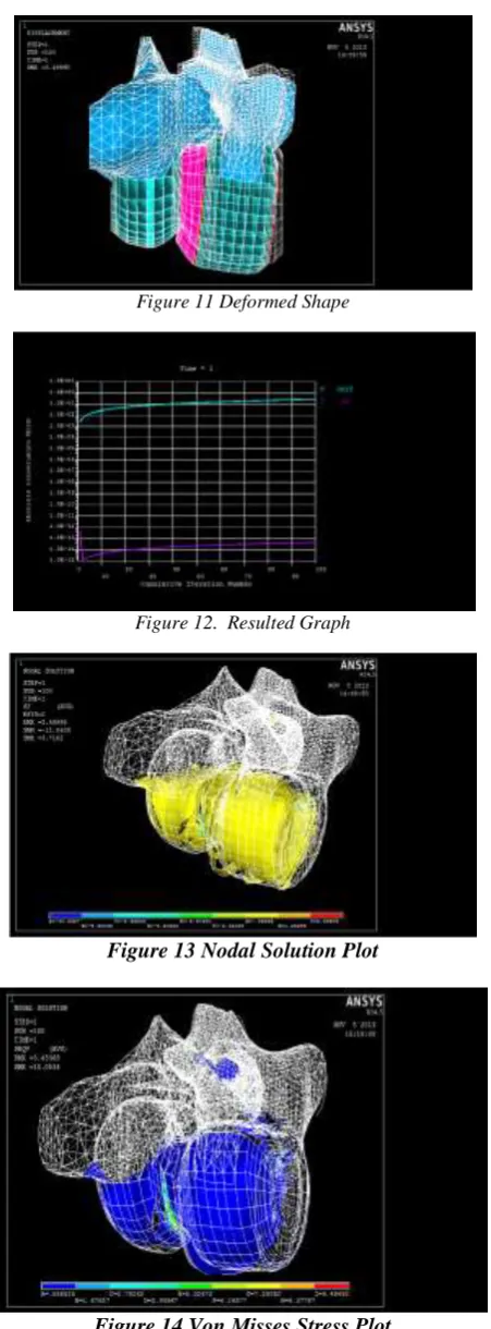
The L4 and L5 lumbar vertebrae were subjected to various boundary and loading conditions. The L5 disc was constrained to zero degree of freedom i.e. fixed. And the compressive force was applied of 400 N magnitude was applied on the L4 endplate, as shown in figure 10, in ANSYS. Also some other plots like nodal and elemental plots, Von Misses stress distributions are shown in following images captures from ANSYS.
Figure 11 Deformed Shape
Figure 12. Resulted Graph
Figure 13 Nodal Solution Plot
Result
It had been observed that the CAD/FEA model when analyzed in ANSYS under 400 N force the lumbar vertebra L5 is displaced by 3.45368 mm when compared to lumbar vertebra L5 without application of the force. Also it had been learned from the above study that the maximum forces were occurred and concentrated mainly on the endplates and the intervertebral disc, as the forces on the vertebral body are uniformly distributed and passed to the next. The final plot for the displacement of the vertebrae under loading conditions is plotted (Figure12).
References
1. Augustus A. White III and Manohar M. Punjabi.Clinical Biomechanics of the Spine, Physical Properties and Functional Biomechanics of the Spine, pg. 1-76.
2. Fabio Galbusera, Chiara M. Bellini,Manuela T. Raimondi,Maurizio Fornari, Roberto Assietti .Cervical spine biomechanics following implantation of a disc prosthesis; January 2008. pg.1130-1132.
3. Geometrical Dimensions and Morphological Study of the Lumbar Spinal Canal in the Normal Egyptian Population.2013 4. Marta Kurutz, Budapest University of Technology and Economics. Finite Element Modelling of the Human Lumbar
Spine.pg.1-10.
5. Marcel Dreischarf, AntoniusRohlmann, GeorgBergmann,ThomasZander.Optimised loads for the simulation of axial rotation in the lumbar spine.pg.2322-2325.
6. Michael A. Adams, Patricia Dolan. Spine biomechanics.2005.pg.1-9