ISSN (Online): 2409-4285 w w w.IJCSSE.org Page: 151-160
Comparative Study: 2D Image Processing In Gray Scale Using
Wavelets
Jose Alfredo Acuna-Garcia1, Sandra Luz Canchola-Mag daleno2 and Fausto Abraham Jacques Garcia3
1, 2, 3 Faculty of Informatics, Autonomous University of Querétaro, Santiago de Querétaro, Querétaro 76230, México
1[email protected], 2[email protected], 3[email protected]
ABSTRACT
The digitization of images has many advantages that could not be taken in past times when occupying film for record images. Image processing allows operations that facilitate the modification of their presentation by means of mathematical treatments that enhancement their visual characteristics, dedicated to specific purposes. The present work is an experimental comparative study to understand the information that can result from Discrete Wavelet Transform of an image in 2D in grayscale, using kernel Wavelet Daubechies. This analysis focus on how many resolutions can get from an original image, convolved with Wavelet Transform and how can the coefficients be modified in different wavelet resolutions to get expected results of a future research Project.
Keywords: Image processing, Wavelet, Multi-resolution, DWT, Daubechies.
1. INTRODUCTION
It's very convenient to start the analysis of a phenomenon that leaves its record in an image, to know the diffe rent tools that can be used to process them in order to achieve pre-established goals. To process the image by means of transforming it to a different domain fro m the original, for e xa mple , to frequency, which is performed with the Fourier Transformat ion, is convenient to accentuate the presence of some of the harmon ics that are present in the image and that are identified in this domain. In the case o f the Wavelet Transformat ion is a more general case than the Fourier Transform, which in addit ion to representing informat ion of the frequencies that compose the image, furthermore provide spatial information of the same , and also allow an analysis of the different resolutions present in the image [1].
The present work is an e xperimental co mparative study, and it analyzes different 2d images in grayscale transformed by means of the Discrete Wavelet Transform (DWT) using the Mallat algorith m as the basis of a mult i-resolution analysis. The results of the transformation in Wavelet doma in was analyzed in terms of possible compression characteristics, frequency bands analysis,
component frequencies of each band, and ease of contrast enhancement in high-frequency bands [2].
Resolution is one of the most important characteristics of an image. Images of low resolution are processed to obtain more enhanced resolution if is required. One technique used for image resolution enhancement is Interpolation. Interpolation techniques have been used widely in many images processing applications such as facial reconstruction [3], mu lt iple description coding [4], and super-resolution [5] [6]. Interpolation increases the number of pixels in the digital image.
Resolution enhancement of images using wavelet do main are new algorith ms have been proposed [7]. DWT and stationary wavelet transform (SWT) are two Wavelet transforms used in image processing. DWT decomposes an image into diffe rent sub-band images, name ly lo w-low (LL), lo w-high (LH), high-low (HL), and high-high (HH). SWT is simila r to DWT but there is no downsampling operation performed. So in SWT, the sub-bands have the same size as the input image. Contrast enhancement of images is done by using singular value decomposition (SVD) on lo w-frequency sub-band of both input and histogram equalized images.
In [9] a method is proposed to contrast enhancement in a grayscale image, based on the Fast DWT using in addit ion to the Unequal Spaced Fast Fourier Transform. Th is special type of Fourier Transform is used in conjunction with the DWT to obtain the coeffic ients of the transform using orientation and spatial location in the image with the objective of improving the contrast. The use of DWT is power by the FFT special using the information of coeffic ients and harmonic frequencies of the image. The results that are obtained as enhancement of the images are important in relation to the images before processing. Other methods used for improve ment contrast use the transform of the orig inal image to frequency doma in using the fast Fourier transform (FFT) and apply filters to improve the contrast at image. The processing can be comple mented with methods such as the DWT. The researcher Haze m used a method called DWT-FFT for through 5 steps to improve the image. The final step of this improve ment is to return the image to original do main (space domain) to see the enhanced results. This research use images in grayscale and indicates that this process at the same time that it imp roved the contrast, decreased effects of unwanted noise [10].
The Aswathy researcher in his research using new techniques such as DWT, DCT and Singular Value Deco mposition (SVD) fo r the contrast enhancement in 2D satellite images in shades of gray. This process starts equalizing the images with a technique Adaptive Histogram Equalizat ion (AHE) and transforming the m into space of the frequency using differently known ke rnels in the frequency domain and returning original doma in. He indicates visual and quantitative improve ments in the efficiency of the procedure, using images in color 2D. He takes a measurement of the contrast based on mean and standard deviation of the result obtained [11].
A proposal to imp rove a signal by eliminating the noise present is in [12]. These proposal study the problems that e xist in the traditional functions of threshold in the determination of noise, using wavelets, and a logarithmic function that sets the number of levels that are obtained fro m the decomposition using DWT. For the defin ition of the new fo rmula for setting the threshold of signal with noise, it analyzes the results of the function that it is proposed, from the approach in the treatment of signals. It proposes to set the threshold in relation to the effect that seeks to reduce the noise of the signal.
The researcher Eun Kim proposes in his research a method for imp roving contrast in color images obtained from the lib rary of NASA. The procedure proposes to modify the low-frequency coeffic ients of the image based on a technique AHE, and the same increase high-frequency coeffic ients, ma king visible contrast enhancement. In addition, uses the techniques of DWT AND DCT transform the frequency doma in each color co mponent of the image separately and fina lly ma king the reconstruction.
Uses a quantitative measurement of contrast of the processed image to evaluate the improvement [13]. A new method to imp rove the contrast of images with low lighting is proposed in [14]. Th is method is based on statistical modeling of the wavelet coeffic ients of an image. Analyzes the statistical distribution of the coeffic ients obtained by Wavelet Transform of an image as a basis for improving the contrast automatically. Th is is an interesting fie ld to discover informat ion that is detailed in the coeffic ients of the wavelet transformation. Results observed exp lains how to imp rove the contrast and reduces the presence of noise in the image. The search for informat ion that is hidden on the coefficients of DWT in the processing of image enhancements can be a great support in the achievement of goals, it should also understand the usefulness of this transformation in the area of image processing.
Also in the area of contrast enhancement, and focused on med ical images fro m Ma mmography, the researcher Lane performs the processing of digital images fro m Mammography. The goal is made an analysis of the images in search of cell aggregations, which may be a sign of breast cancer. For this identificat ion processing is performed using a frequency analysis with Wavelets, decomposing at different resolutions, discovering the image resolution that facilitates the identification [15]. Results of the present work focus in analy zing how many resolutions can get fro m an origina l image, convolved with Wavelet Transform and how can the coefficients be modified in d ifferent wavelet resolutions to get expected results of a future research pro ject. Fu rthermore, each partial result is analyzed in the frequency bands and is commented their possible use in enhancement of the image. The present document is divided into 5 sections including this introduction. In the theory section establishes the theoretical foundations of the Wavelet Transform (WT), types, kernels and algorithms. In methodology section establishes the steps to perform the tests that will be shown in the ne xt section. The results section shows many images processed and the characteristics that are observed in each transformation. Finally the last section present conclusions and possible future studies that can be detached fro m the current one.
2. THEORY
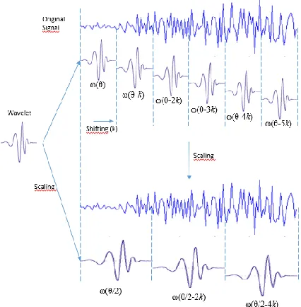
informat ion. Th is transformat ion store time, spatial and frequency information from the original signal or image. The process of transforming a signal through the use of Wavelet methodology is called convolution and consists of using a "small wave" previously defined, to integrate it with an original signal. Th is little wave is known as "Ondeleta" in Spanish, or “Wavelet” in English. Figure 1 shows the process that is used to do the convolution.
Fig. 1. Convolution process of a signal with Wavelet transform ation.
Figure 1 shows an original signal (upper signal in the figure) and a wave let to filter in high resolutio n the original signal, called ω (θ). This Wavelet e xists only in a defined time and outside of that time does not exist, and it is convolved with the original signal obtaining the coeffic ients of the transformation that represent that space. Then the same time-shifted Wavelet ω(θ-k) is applied to the original signal, obtaining all the coeffic ients of that resolution. k is the time-shifted parameter.
To obtain another resolution, to filter a d iffe rent band, the Wavelet is modified in frequency which is called scale Wavelet and is represented as ω(θ/2) and is convolved with the orig inal signal, obtaining coeffic ients in this resolution.
A image is defined f(x,y) with dimensions M x N, the transform function T(u,v,...) is expressed in eq. (1).
𝑇(𝑢 ,𝑣, … ) = ∑ 𝑓(𝑥, 𝑦) 𝑥 ,𝑦
𝑔𝑢 ,𝑣,…(𝑥, 𝑦).
(1)
Where x and y a re spatial variables, u,v,… are variables result of the transformation, in the transform domain. Inverse process can be done if given T(u,v,…), with discrete inverse transform can be obtained f(x,y) in eq. (2).
𝑓(𝑥, 𝑦) = ∑ 𝑇(𝑢, 𝑣, … ) 𝑢,𝑣,…
ℎ𝑢 ,𝑣,…(𝑥, 𝑦).
(2) In these equations 𝑔𝑢 ,𝑣,… y ℎ𝑢,𝑣,… are called the kernels of transformation, this pair is for forwa rd and inverse transformation, and define the computational co mple xity, and usefulness.
One of the algorithms that probably is the most used in the area of DWT, is the algorith m of Mallat, for the Multiresolution Analysis (MRA). This analysis has become a great application tool for image processing [1]. The MRA analysis based on Wavelet technology uses an image and decomposes this two-dimensional data into components of different frequency, allowing to study each component with a d ifferent resolution that is according to its size. The detail of the image is thus decomposed into a frequency component, which can also be located in the physical space structures of the image. Th is decomposition is composed of ele ments of different sizes according to the resolution being analyzed. The larger ones are thick resolutions, related to low frequencies, and smaller or thin resolutions represent high frequencies [2].
The DWT also allows in the MRA to extract the informat ion of the resolution and of the space that is being analyzed in the image. Th is transformat ion collects for each resolution information of the horizontal, vert ical and diagonal detail of each space of transformation [2]. The Daubechies wavelet has the characteristic of be ing orthogonal and biorthogonal, and it is possible to process it continuously and discreetly. In this wavelet, an order is defined to convolve it with a signal. Th is order is defined as the definition points with which the Wavelet shape is defined in its graphical representation, mathe matica lly defines the number of coeffic ients that define it. For e xa mple , the Haar Wavelet is a special case of the Daubechies DB1 Wavelet, with two definition points. Figure 2 shows definition points of Wavelet Db2 for h igh pass filter.
(a) (b)
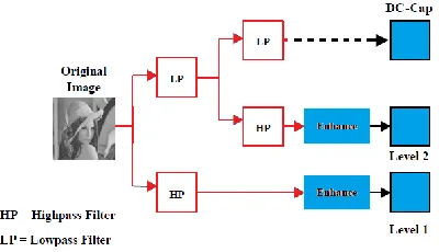
For DB2 order, the four defin ition points that compose it are shown in figure 2. In its transformat ion Wavelet scaled and shifted is applied to ach ieve the filte rs of the process that is presented in figure 3. This is a filter process obtains the coeffic ients of the resolution that corresponds to the filter that is applied (high or low pass band).
Fig. 3. DWT process: filter banks.
3. METHODOLOGY
The present work has as a goal the quantitative and qualitative analysis of image processing by means of Wavelet Transform. Is quantitative because analyze the resolution of the images, the ranges of coeffic ients that are obtained by the transformation, and the characteristics of each range of coefficients. It is qualitative because it analyzes the result of the reconstruction of the image using diffe rent resolutions Wavelet and analytically observes the differences of each reconstruction.
The work begins with an analysis of the Mallat a lgorith m for the DWT in 2D and its imple mentation in the transformation and inverse transformation in the Python 3.6 progra mming language. 2D images are selected and transformed to grayscale at 8 bits per pixe l resolution. For this e xperimental ana lysis, several free images were selected from the site https://pixabay.com. Each pre-processed image is at 8-bit grayscale format. 40 images were processed and finally only 5 were considered illustrative and were chosen for the purposes of showing the results of the DWT application. The DWT algorithm is applied to the selected images and extraction of its main characteristics of the transformation (d imensions and coeffic ients), and on the processed images the detailed
analysis of characteristics is performed. A detailed analysis of Wavelet resolutions of higher resolution and smaller resolutions is also performed in directional components of the transformation.
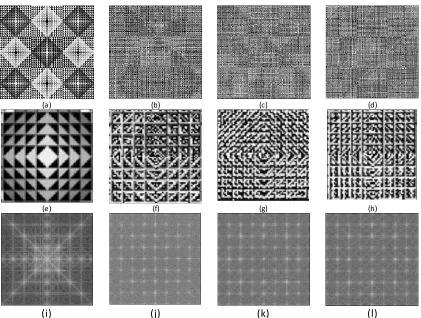
Table 1:. Images and frecuency histograms: images 1(a), 2(c), 3(e), 4(g) and 5(i); histograms in (b), (d), (f), (h) and (j).
(a) (b)
(c) (d)
(e) (f)
(g) (h)
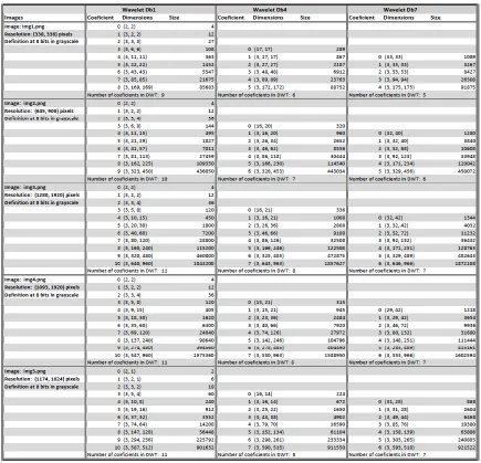
Table 2: Coefficients of DWT applied to im ages selection
4. RESULTS
Analyzing the selected images by means of image processing tools with the intention of achieving an improve ment in so me of its features will depend large ly on the tool that is chosen. The five images were selected because they has special characteristics used in this work. The selected images and their frequency histogram are presented in Table 1.
Table 1 shows images 1, 2, 3, 4 and 5 and to the right the histograms of frequencies corresponding to each one. The distribution of the frequency histogram is different in each image. Images 1 and 2 show a distribution that focuses more on light and dark tones, with a relatively low number
of intermediate tones, making these images the highest contrast of all. Image 3 shows a histogram with a tendency toward very dark tones and distribution of intermediate tones. The images 4 and 5 present more balanced distributions towards the gray tones, having a little presence of tones or very white or very black. In addition, it can be observed that the resolution in pixels of the images are interesting for their distribution and for the application of DWT.
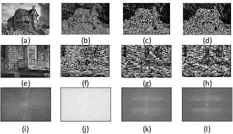
Table 3: DWT of im age 1 an last-high resolution: Original Image(a), Reconstruct Db1(b), Reconstruct Db4(c), Reconstruct Db7(d), Central Zoom(e), Reconstruct Db1(f), Reconstruct Db4(g), Reconstruct Db7(h), FFT Original Image(i), FFT Rec Db1(j), FFT Rec Db4(k), FFT Rec Db7(l).
(a) (b) (c) (d)
(e) (f) (g) (h)
(i)
(j)
(k)
(l)
show important characteristics of the processed images. The definition in Db1 have a Wavelet Definit ion (WD) of 2 points, the Db4 presents a WD of 8 points, and the Db7 presents a WD of 14 po ints that define Wavelet according to the application of its equation. The coeffic ients of each wavelet resolution and its characteristics are presented in Table 2.
Table 2 shows characteristics that are obtained when applying the DWT to selected images. In this images can be observed how in the last-high resolution of Wavelet obtain elements of the half of the resolution of the image in p ixe ls for the Db1 and a few points superior in the transformation of DB4 and Db7, due to the applicat ion of a Wavelet with big points of definition in itself. When using 2 Wavelet resolution points in Db1, in the algorith m on ly 2 points of the image in p ixe ls are taken to operate the transformation in two d imensions, a fra me of 2 x 2 is taken, and the transformation is the reflection of only the pixe ls that are transformed. In th is way, when transforming image 1 o f 338 x 338 pixels, the ma ximu m resolution in wavelet is 169 x 169 e le ments. Each ele ment represents the integration with the wavelet in
three directional co mponents : vertical, horizontal and diagonal. It has the highest resolution three matrices of 169 x 169 one in each direction. The sa me description operates on each of the images, considering the difference in pixels resolution.
When using the DWT with Db4, at the last-high resolution a Wavelet transformation simila r to DB1 is obtained, But the transformat ion involves not only the 2 pixe ls like Db1, but also it involves the neighborhood of those two pixels, performing the convolution on 8 pixels to represent them in a Wavelet space of 2 x 2 p ixe ls in 2D. By using the pixe l neighborhood, a higher Wavelet resolution is obtained, which for image 1 of 338 x 338 pixe ls, is 172 x 172, slightly larger than that of BD1. In the same way, 3 matrices are obtained for each direction with the DWT.
It can also be noted that for DWT, several levels of coeffic ients were obtained, and depending on the WD used, Db1, Db4 o r Db7, the leve ls decrease inversely with the increase in Wavelet definit ion. Thus for image 1, WD Db1 is represented with 9 levels of coeffic ients, whereas Db4 only counts with 6 and Db7 with 5 levels. Each of these levels represents a set of WFB coeffic ients. Because the Mallat a lgorith m is started by filtering the higher frequencies, the last-high WFB a re obtained with this filter (in table 2 a re the coeffic ients of higher levels, in Db1 for image 1 is the level numbered with 8). This same behavior is repeated for all images, considering the variations that each one has in pixels resolution, affecting the ma ximu m WFB and the number of levels of coeffic ients that are obtained from the DWT. The higher resolution in pixe ls makes possible the better resolution in Wavelet. In this way, the 8 image of 1373 x 1920 pixe ls, at its highest resolution Wavelet for DB1 is 687 x 960 in the three directional mat rices, simila rly to the resolutions for Db4 and Db7.
It is important to note that the lowest Wavelet resolutions are obtained with the application o f Db1, where the numbered levels with "0", have representations of 2 x 2 in a single matrix, and the second levels already have three matrices for the three directions. This is because in the DWT the Wavelet is scaled to its larger size, encompassing a greater number of pixels to represent, and presenting low WFB and few coeffic ients in each level. This same leve l e xists in each of the images in the application of the different WD.
Table 4: DWT of image 1 in second-last high resolution: Original Im age(a), Reconstruct Db1(b), Reconstruct Db4(c), Reconstruct Db7(d), Central Zoom (e), Reconstruct Db1(f), Reconstruct Db4(g), Reconstruct Db7(h), FFT Original Image(i), FFT Rec Db1(j), FFT Rec Db4(k), FFT Rec Db7(l).
(a) (b) (c) (d)
(e) (f) (g) (h)
When transforming the image, decompose the image into the wavelet coeffic ients that compose it, and apply the inverse transformation DWT it reconstructs the original image. Table 4 shows the origina l image 1 and the reconstructed images working only with the coeffic ients of the last-high WFB (leve l 8 of Db1 and corresponding in each WD) in its three directional components . In the image do ma in, it can be seen how some o f the darker
pixe ls of the original image a re better highlighted in the reconstruction of only the highest WFB in Db1, that in WD Db 4 or Db7, because the algorithm considers in Db1 more e xclusively the matrix of 2 x 2 pixels in convolution.
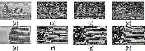
Table 5. DWT of image 2 in last-high resolution: Original Image(a), Reconstruct Db1(b), Reconstruct Db4(c), Reconstruct Db7(d), Central Zoom(e), Reconstruct Db1(f), Reconstruct Db4(g), Reconstruct Db7(h), FFT Original Image(i), FFT Rec Db1(j), FFT Rec Db4(k), FFT Rec Db7(l).
(a) (b) (c) (d)
(e) (f) (g) (h)
In Table 3 (e) the image 1 is shown in central approach, and the detail of the same reconstruction is observed for the three integrated Wavelet resolutions. In the inverse transformation with Db1, Db4 and Db7 reconstruct in detail the vertical, horizontal and diagonal ele ments of the highest Wavelet resolution, especially the WD Db1 has more visib le diagonal e le ments than Db7. In Db4 you can notice the presence of more diagonal ele ments than horizontal and vertical. This analysis is important if the purpose of image processing is to highlight any of th ese characteristics.
Table 6: DWT of image 3 second-last high resolution in horizontal: Original Image(a), Reconstruct Db1(b), Reconstruct Db4(c), Reconstruct Db7(d), Central Zoom (e), Reconstruct Db1(f), Reconstruct Db4(g), Reconstruct Db7(h), FFT Original Image(i), FFT Rec Db1(j), FFT Rec Db4(k), FFT Rec Db7(l).
(a) (b) (c) (d)
(e) (f) (g) (h)
(i) (j) (k) (l)
that implies the presence of intermed iate frequencies than in the original, wh ich imp lies a more h ighly atomized contrast in this representation. In some other image with less contrast than these, could be interpreted as a signal with noise. This denotes the presence of higher contrast in at very high resolution.
In table 3, with the WD Db4 and Db7, it is observed how the image (considering in the transformation but the neighborhood of the WD Db 1) the nu mber o f frequencies present in the FFT, in intermed iate points of the graph decreases, i.e. the points are grouped in values more defined than in Db 1. Th is imp lies that the harmonic frequencies are concentrated more at certain points. In the origina l image, it is observed more that concentration to be working with a well-defined image.
Table 4 shows the image 1 and its transformation with the DWT and its reconstruction with the coefficients of the second-last high resolution in its three directional components, in wh ich it can be observed that the resolution Wavelet in this level is composed of ele ments of 4x4 pixels, being lower resolution than the one analyzed in table 2. In the zoo m central section of the image (e) with the reconstruction Db1 not very clear details of the Image, whereas the WD DB7 shows the good definition of diagonal e le ments but less WFB. The analysis with the FFT of the WD Db 1 (b) presents a very clear image, which represents a great dispersion of harmonic frequencies in the image, there are many points very contrasting in that reconstruction. The WD Db4 and Db7 present a scheme of frequencies very simila r to the one presented in table 3. Also, it is notorious the diffe rence between the high WFB and the second -last-high resolution in its simple visualization.
Table 5 shows the reconstruction of the image 2, using only for the reconstruction the last-high WFB in addition only the coeffic ients in the horizontal d irect ional component is considered for reconstruction. In the reconstructions Db1, Db4 and Db7, the presence of horizontal e le ments, very fine in Db1 due to their local reconstruction, is more present in WD Db 4 and Db7. More ele ments with horizontal co mponents are in the neighborhood. In WD Db 4 and Db7 can be observed that the presence of more horizontal e le ments than the original image, this effect is compensated in the reconstruction with the presence of the coefficients of the other levels. Especially in the reconstruction using Db7 is observed in the image with central zoom, are in the middle part of the image to the right and le ft frequent horizontal lines that are not presented in the original image in the same sector, because it works with neighborhood pixe ls for the transformat ion of each point of WFB.
In the processing of the image 3 in table 6 with the second-last high resolution in Wavelet, only with the horizontal reconstruction, it can be observed in zoom
central region of the magnified image, where the image have a balcony, this zone presents a greater a mount of vertical e le ments, in the reconstruction, appears a darker area, representing the absence of elements in horizontal resolution. Especially accentuated in the Db7 by working with more pixe ls in the neighborhood of each of the points in the WFB. In addit ion to analyze the images using FFT, it is possible to observe how the DB1 definit ion presents a graph with the presence of harmonics in a lmost all ele ments of the FFT image, denoting a saturation of frequencies achieved by this reconstruction. The other FFT representations of the harmonic image represented are more similar to those of the original image 3.
Table 7: DWT of image 4 in third-to-last resolution in horizontal: Original Image(a), Reconstruct Db1(b), Reconstruct Db4(c), Reconstruct Db7(d), Central Zoom (e), Reconstruct Db1(f), Reconstruct Db4(g), Reconstruct Db7(h), FFT Original Image(i), FFT Rec Db1(j), FFT Rec Db4(k), FFT Rec Db7(l).
(a) (b) (c) (d)
(e) (f) (g) (h)
In the image 4 presented in table 7, it is a lso clear the presence of horizontal ele ments, and especially in this image to be analy zed in the third-last high WFB, allows analyzing this resolution by the own characteristics of the original image in Pixe ls. The image is 1093 x 1920 pixels, so at this Wavelet resolution level obtained is 137 x 240, which is identifiab le in the reconstruction. If this level is analyzed in the image 1, with WD Db 1 it have 43x43 of WFB, which would not be so representative of the image to be able to highlight some feature directly in the original image (these coeffic ients fulfill their function in inverse transformation with comp le mentary reconstruction ele ments at lo w WFB). The resolution of the original image is fundamental to be able to ma ke decisions of the wavelet resolution leve l with wh ich the image processing obtain the aimed result.
Table 8: DWT of image 5 in second-to-last resolution: Original Im age(a), Reconstruct Db1(b), Reconstruct Db4(c), Reconstruct Db7(d), Central Zoom (e), Reconstruct Db1(f), Reconstruct Db4(g), Reconstruct Db7(h), FFT Original Image(i), FFT Rec Db1(j), FFT Rec Db4(k), FFT Rec Db7(l).
(e) (f) (g) (h)
In image 5 presented in table 8, a radiolog ical image is shown, with origina l resolution of 1174 x 1024 p ixe ls. When process a reconstruction with the second-last high WFB in comp lete resolution, the differentiation of vertical and horizontal ele ments in the WD Db1 can be clearly observed. It can be seen that it is possible to perform the image p rocessing by modifying these coeffic ients in order to increase the resolution of the horizontal, vertica l and/or diagonal characteristics of the image. As the definition increases in WD Db 7, the horizontal e le ments increase in length as well as the vertical ones as a result working with more p ixe ls in the neighborhood of the original image. But it is also observed that there is no big difference between the definit ion Db4 and Db7. In the horizontal only reconstruction image, it is possible to notice a greater elongation of the horizontal ele ments and especially a b ig thickness in the individual horizontal e le ments between WD Db4 and Db7.
5. CONCLUSION
This research suggests the dependence that exists between the resolution of the original image and the ma ximu m resolution that can be obtained in wavelet, in its highest resolution coefficients. It is concluded that at lower resolutions in the original image, also fewe r layers of Resolution in Wavelet.
DWT provides a powerful tool in image processing when the aim is to give greater enhancement to well-identified ele ments in image spaces considering the WFB that is presented in its different levels and direct ional components.
Using DWT it is possible to analy ze the image in re lation to the frequencies that occur in certa in areas of the image and to be able to perform the processing on the zones of interest. It is possible to modify the coeffic ients of these areas of interest to emphasize their p resence of target ele ments, while in other areas the presence of these coeffic ients can be attenuated. Depending on the resolution level of the coefficients, which represent a resolution filter band, undesired ele ments may be highlighted or attenuated.
In the field of noise reduction present in an image, with the WDT it is possible to analyze this issue and attenuate the coefficients related to the presence of this effect. Contrast enhancement is possible when using the DWT,
by highlighting Wavelet resolutions related to improving coefficients related to desired enhancement elements. This study is the first step of future studies planned in relation to the processing of images in specific areas of scientific interest to be able to highlight or attenuate the presence of effects that allow the improve ment of the image based on established goals. For future works it's intended to develop a research on the use of wavelets in radiologica l images, in order to achieve improve ments fro m a medica l point of v iew. It is intended to make a computer image improve ment tool using Wavelets to support researchers who wish to analyze the possible image processing under this tool, parameterizing the ma in variable ele ments that are shown in the processing of the images presented in this study.
ACKNOWLEDGMENTS
Special thanks to Faculty of In formatics of Autonomous University of Querétaro for the support given to me, and to the researchers Sandra Luz Canchola Magdaleno and Fausto Abraham Jacques Ga rcia , for a ll the time they have devoted to support this research.
REFERENCES
[1] R. E. W. Rafael C. Gonzalez, “Digital Image Processing”, Pearson Prentice Hall, 2014.
[2] S. Mallat, “A Wavelet Tour of Signal Processing”, Academic Press is an imprint of Elsevier, 2009. [3] S. Z. Yi-bo Li, H. Xiao, “The wrinkle generation
method for facial reconstruction based on extraction of partition wrinkle line features and fractal interpolation,” Proc. 4th Int. Conf. Image Graph, 2007.
[4] S. E. Yuksel Yapici, Begum Demir, “Downsampling-based multiple description coding and post-processing of decoding,” Proc. 27 Chinese Control Conf, 2008. [5] G. A. Hasan Demirel, Sara Izadpanahi, “Improved
motion based localized super resolution technique using discrete wavelet transform for low resolution video enhancement, scotland,” Proc. 17th Eur. Signal Process. Conf, 2009.
[6] H. P. Yinji Piao, ll-hong Shin, “Image resolution enhancement using inter-subband correlation in wavelet domain”, Int. Conf. Image Process, 2007.
[7] [7] G. A. Hasan Demirel, “Satellite image resolution enhancement using complex wavelet transform”, IEEE Geoscience and Remote Sensing, 1991.
[8] A.-A. Zohair, S. Ghazali, D. Amjad, S. Tanzila, “An innovative technique for contrast enhancement of computed tomography images using normalized gammacorrected contrast-limited adaptive histogram equalization”, EURASIP Journal on Advances in Signal Processing, 2015.
Fourier Transform (FDCT-USFFT)”, International Journal of Electronics Communication and Computer Engineering, 2016.
[10]R. R. M . Abdullah M . Hammouche, Hazem M . Al-Bakri, “Image contrast enhancement using fast discrete curvelet trasform via unequally spaced fft”, M ansoura University, 2016.
[11]M. L. Aswathy Mohan, “Image enhancement using dwt dct and svd”, Journal of Engineering Research and Applications, 2014.
[12]Y. D. Lu Jing-yi, Lin Hong, “A New Wavelet Threshold Function and Denoising Application”, Hindawi Publishing Corporation, M athematical Problems in Engineeringe, 2015.
[13]S. E. Kim, “Image contrast enhancement using entropy scaling in wavelet domain”, Department of Electronics Engineering, Pusan National University, 2016.
[14]A. A. Artur Loza, David Bull, “Automatic Contrast Enhancement of Low-Light Images Based on Local Statistics of Wavelet Coefficients”, Elsevier: Digital signal processing Volume 23, Issue 6, 2013.