Foundation of Computer Science FCS, New York, USA Volume 3– No.9, August 2012 – www.ijais.org
19
Tracking of Person using Monocular Vision by
Autonomous Navigation Test Bed (ANT)
Sachin Kansal
ArtificialIntelligence Lab,RoboticsDepartment,IIIT Allahabad
Neha Garg
Computer Science Department, Suresh Gyan
Vihar University, Jaipur
Pavan Chakraborty
Phd,Assistant Professor,Robotics Department,
IIIT Allahabad
ABSTRACT
This paper has the capability to detect the person and follow that person by the surveillance mobile robot (ANT) in outdoor and indoor environment. Monocular based vision tracking technique used in the paper and following method used for surveillance robot is proposed, as it combines face detection, person’s upper body features extraction and Moment calculation modules proposed in this paper. We are extracting torso based color as a key feature after face detection; it gives the features as input to the module named moment calculation which is used to track the target person by calculating the motion parameters. We introduce speech generation module in order to develop interaction between the person and surveillance robot. We also introduce wireless communication in order to send the signal from base station to the remote location to know where ANT is located. Experiment results validate the robust performance of the proposed approach.
Keywords
– Face Detection; Mobile robot; Tracking and following; Color features; Moment Calculation; Speech Generation; Wireless Communication1. INTRODUCTION
Continuous and reliable tracking of a person is difficult job for a surveillance robot in the dynamic indoor and outdoor environment, having uncontrollable lighting conditions. As There are many existing methods which is implemented in order to track a person by a surveillance robot using laser range finders [1][2], and some are rely on proximity sensors such as visual methods [3]-[5], some use the concept of laser by having additional feature of localization by using microphones from sound source.[6], we also have a combination of range and visual information get it from sonar sensors [7] .As none of them having the capacity of tracking the target person effectively. However the above tracking techniques are applicable for the monocular vision system .In this paper specific person is tracked by calculating the motion parameters using monocular vision system mounted on the surveillance robot. As we compute the motion parameters (Away, Towards, Right, Left) for every sample frame and instruct the service mobile robot accordingly.
The paper is organized as follows: Section 2 briefly describing the method of framework. Section 3 depicts the detailed approach of target person tracking. Section 4 depicts the hardware description which is used as a surveillance robot Section 5 depicts the performance of tracking target person having different distances from the service robot and having different ambience of lightning condition. Finally, in the Section 6 we have the conclusion and future work.
2.
THE METHOD FRAMEWORK
For tracking of the target person we first have to identify the person to whom we have to track and follow. Once the person is found, we adjust the horizontal position of the camera pan-tilt (PTZ camera), and then mobile robot switched to follow the target person by detecting the torso color. After detecting the torso color we compute the moments and finally we calculate the motion parameters after doing the calibration of the camera for a better result throughout. The framework of the tracking and following method is shown in Fig.1 above.
3. ROBUST PERSON TRACKING
To begin the track by the robot, the first frame serves as the first torso color – based model after the Face detection module. As the mobile robot following a person needs a very high real time processing and due to this we have a dynamic changing of the background. To detect the torso wearing the color of the clothes we use color-based features, which can improve the real time performance.
Fig. 1: The framework of the tracking and following method
Image
Face Detection
Color Detec-tion
Thresh-old of Image
Mo-ment Calcula-tion Calculate
Centre (x, y) ANT
3.1 Face Detection
In this module we capture the frame and detect the face of the Target Person in order to provide the Upper Body features of the target person to the next subsequent module. We are using a haar classifier that work on haar-like features. We trained it with a few hundreds of object samples. (i.e., a face or a bus), called positive examples, and these are also scaled to the same size (say, 40x40), and we take negative examples, like- arbitrary images of the same size. After the training of the classifier, it can be implemented to a region of interest (ROI) (as size is same as was in the training) in an input image. Thus a classifier outputs "1" if region is likely to show the object efficiently (i.e., face/bus), and "0" otherwise.
3.2 Color Detection
In this Module taking output of previous module as input to this module, we extract the Body feature (color) of the target person, i.e. We Calculate the HSV (HUE-SATURATION-VALUE) on some points and from that sets a range of HSV of the Target Person in order to provide the feature to the next module to track the person. In this Module once we detect the Face it will automatically computes the point’s i.e points having the HSV values within the range of the region (upper outfit of the target person) from this we set range of HSV. For multiple People, we use a common range module that work on firing the face recognition as user input the face of target and then we detect the target face and compute the HSV range of that person only in an era of multiple peoples in the real time environment.
As due to the lightning conditions, we have chosen HSI as color space. After detecting the color we Threshold the captured image and find the HSI range in order to in order to provide the values for the next subsequent module. A morphological closing operator used for removing of the scattered and noisy region. An example for segmenting the image is shown in Fig. 2.
3.3 Moment Calculation
In this module by taking the range of HSV of the target person as input every time we perform the following techniques described below:
Step 1: From the camera (Logitech C510) we grab the frame continuously from the environment.
Step 2: For each frame we are thresholding the input image.
Step 3: After thresholding we have to compute the HSV of the captured frame from the camera.
Step 4: In this Step we set the HSV range for the targeted person.
Step 5: We calculate the moments from the threshold image.
Step 6: We calculate the centre coordinates (Xo, Yo) of the target person for each captured frame.
The function cvGetSpatialMoments () retrieves the spatial moment, which in case of image moments is defined as: a) Compute the zeroth moment
M10 = ∑x ∑y I(x, y)
b) Compute First Moment for x and y
M10 = ∑x ∑y x I(x, y);
M01 = ∑x ∑y y I(x, y)
Where I(x, y) is the intensity of the pixel (x, y).
c) Compute the mean search window location
Xo = M10 / M00 : Yo = M01 / M00
After using the steps we get the Centre coordinates C (Xo,
Yo) and from this we can provide this parameter the next
module in order to compute the Motion Parameters.
3.4 Calculation of Away and Toward
Pa-rameter
For calculating the Motion Parameters We performs this technique on every 3rd frame to perform we follow steps given below:
Step 1: From the captured frame we calculate the HSV.
Step 2: After getting HSV range of targeted person, and applying threshold on Image HSV.
Step 3: Erosion and Dilation to remove the noise from Threshold image.
Step 4: From the captured window applying search on that HSV region to get coordinates i.e. (Ymax, Ymin).
Step 5: Height of Object in Window (h) = Ymax-Ymin.
Step 6: From the Scaling Factor we can calculate (H obj).
Hobj = Himg * Sf (a)
(c) (d)
(b)
21
3.4.1 Towards Calculation
If we move towards the surveillance robot, image height
increased by some factor (say x) so the new height of image in the window then we calculate the distance domain i.e. we have the Pixel to Meter mapping factor (Sf).
From this parameter we can fire the Backward Module to the
(Himg=Himg+x) ANT (Autonomous Navigation Tested) to the distance ∆ d= (x*Sf) meters.
So now; Hobj= (Himg+x)*(Sf)
Thus from this we can easily move our ANT Away to target person with the calculated distance (∆d).
3.4.2 Away Calculation
As we move away from surveillance robot the height of the image reduced by some factor (say x), the new height of image in the window (H img= Himg-x) then from this we calcu-late distance domain i.e. we have the Pixel to Meter mapping factor (Sf).
From this parameter we can fire the forward Module to the ANT (Autonomous Navigation Tested) to the distance ∆ d= (x*Sf) meters.
So now; Hobj= (Himg-x)*(Sf)
Thus from this we can easily move our ANT towards the target person with the calculated distance (∆d).
Away and towards calculation technique represented by the following results shown below:
Step 1. Initially the target person is about 1.5 meter (m) from the Autonomous Navigation Test bed (ANT).
3.5 Calibration Techniques
In this we calibrate in order to have accuracy in order to find all the four motion parameters.
In fig.3, the object is d (metres) from the camera. So, from the
camera viewpoint there is a View plane from that we can have
a view range of the camera in the distance (d metres).
The Total View plane is having (2β) so from this we can have
the calibration of the camera.
3.5.1 Threshold Condition
If (θ > βl): fire the Left Module of the ANT.
If (θ < βr): fire the Right Module of the ANT.
Else: do not fire any module of the ANT.
So; 1 Pixel represents = [tan-1(d/D)*Sf] degrees.
If we move Right then we map the pixel to the distance moved by the target position and through this we can calculate the distance (in metres) covered while moving in Right direction (∆dr meters).
If we move Left then we map the pixel to the distance moved by the target position and through this we can calculate the distance (in metres) covered while moving in Right direction (∆dl meters).
So, from the (∆dr meters) and d (meters) we can calculate the Tanβ.
i.e. Tanβl = (∆dr)/D
Tanβr = (∆dl)/D
Where; β=βl+βr
In order to set the threshold whether to fire the Left or Right Module of the ANT to do the functioning in a efficient and effective fashion.
3.5.2 Sequencing Method (For Determining Right and Left Parameters):
In sequencing method is used to obtain the motion characteristic of a target person. The steps used to compute the moment’s calculation are discussed below:
Step 1: For generating the information regarding speed of motion, we take the two images at known time interval.
Step 2: Calculate their respective Centre of Mass (Xc, Yc)
using Moment Calculation technique.
Step 3: Now we calculate the motion parameters (dx/dt) using
the equation (3.a).
dx/dt = (Xc2-Xc1)/T ………… (3.a)
Here, T is the Time interval between two taken images.
Ob-ject
∆dr
(me-tres)
β ll β r
D (meters)
Xc1 is the X coordinate of centre of mass image 1 taken
a time t.
Xc2 is the X coordinate of centre of mass image 2 taken
a time t+T.
dx/dt is the speed of motion of target in X direction.
Table 3. Rules for estimating direction of motion on the basis of dx/dt
3.6 Speech Generation Module
Speech generation module is used for having interaction with the person and the ANT (Autonomous Navigation Test bed). By using createprocess() function we create a thread for speech generation. Prototype of the speech generation is given below:
3.7 XBee Pro RF module
The XBee Module is a drop-in wireless solution that transfers a standard asynchronous serial data stream. We use this module as transmitter and receiver (for wireless connection).It is having 900 MHz frequency. It is having indoor range up to 370m and in outdoor environment with high gain antenna range up to 20km in line-of-sight.
4.
SERVICE
ROBOT
HARDWARE
DESCRIPTION
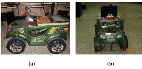
The hardware platform of the mobile robot we used named ANT (Autonomous Navigation Test bed) in Fig.4 (a), 4(b). With an on-board laptop (Intel(R) core(TM) i5 label processor, 2.4 GHz) for image processing. For controlling the motors we use Microcontroller at mega (16). We have implemented USB port programming so that we can send the output after image processing to the USB port defined to be
Asynchronous Receiver/Transmitter).Logitech C510 webcam is mounted on top of the robot at a height of (x cm). We have enabled Wi-Fi (Wireless Fidelity) for remote access.
And also used microphones i.e. (Speech Module) to be interacted with user in order to take the commands and speak according to the situation. We have used Dual Motor Driver for a continuous feedback in order to have a smooth traversing by the surveillance mobile robot. The algorithm is tested on C++ on the Linux environment. Person tracking with a service mobile robot is a highly dynamic task in a real time environment and it will also send the video streams from the remote location to the base station.
5. EXPERIMENTS
5.1 For Away and Towards: Step 1. Initially the target person is about 1.5 meter (m) from the Autonomous Navigation Test bed (ANT).
Step 2. Then target person moves away from the ANT i.e. about 0.8 meters (m) then calculate threshold and then finally calculate the area which less than previous area. If the differ-ence in area from two captured frame not in range of thresh-old and then we instruct our ANT to move towards the target-ed person.
Value Direction Indication
dx/dt Positive The object is moving from left to
right across the field of view.
dx/dt Negative The object is moving from right to
left across the field of view.
(a) (b)
Fig. 4:ANT (Autonomous Navigation Test bed)
PROCESS_INFORMATION child1, child2;
char szPath[] = "C:\\Program Files (x86)\\K-Lite Codec Pack\\Media Player Classic\\mplayerc.exe";
BOOL val_child1 = CreateProcess(szPath,"D:\\Latest Backup\\latest\\ intro.wav", NUL, NULL, FALSE ,0, NULL, NULL, &si, &child1) ;
(a)
(b)
23 Step 3. Then target person moves towards the ANT i.e. about
0.8 meters (m) compute the threshold and then finally calcu-late the area which more than previous area. If the difference in area from two captured frame not in range of threshold and then we instruct our ANT to move away from targeted person.
Step 4. Then target person moves more towards the ANT i.e. about 0.8 meters (m) compute the threshold and then finally calculate the area which more than previous area. If the differ-ence in area from two captured frame not in range of thresh-old and then we instruct our ANT to move away from targeted person.
Fig. 5.1: (a) initially target person captured image. (b) Initially target person threshold image. (c) Target person captured image away from the ANT.
(d) Representing threshold image away from the ANT.
(e) Target person captured image towards (0.8 m) the ANT.
(f) Representing threshold image towards (0.8) the ANT.
(g) Target person captured image towards (1.2 m) the ANT.
(h) Representing threshold image towards (1.2 m) the ANT
5.3 For Right and Left
For calculating the right and left motion parameters we use
Table 3.
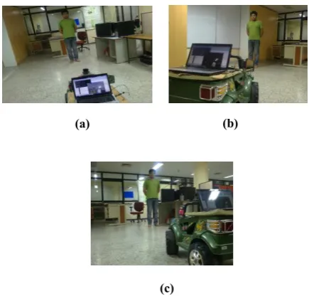
Step 1. Initially for demonstration target person in middle position at a distance from the ANT as shown below in fig. 5.2 (a).
Fig. 5.2: (a) initially target person position. (b) Current target person position i.e. to the left with
re-spect to ANT.
(c) Current target person position i.e. to the right with respect to ANT.
Step 2. Then target person moves to right. So; in order to track ANT moves to the left and at distance from the ANT as shown below in fig. 5.2 (b).
Step 3. Then target person moves to the left. So; to track ANT moves to the right and at distance from the ANT as shown below in fig. 5.2 (c).
6. RESULTS
The image resolution is 640x480.The distance between the target person and the surveillance mobile robot is varies from 1.2 m to 3.5 m. The results we are presenting were at 5 fps (frames per second). The method we are using having about 99% average correct rate and have 1% average false positive rate. As we are experimenting at various distance s from 1.2 m to 3.5 m having a step of 0.6 m.For considering the practical scenario if the target person is out of the scope of the surveillance mobile robot than it check for each frame and if no person is found on the successive 10th frame, the mobile robot will stop and it search the target person by moving their pan-tilt camera.
7. CONCLUSION AND FUTURE WORK
The method for calculating the moments which results in computing all the motion parameters by the rule matrix as it feeds the surveillance mobile robot as input and performs accordingly in order to track the target person in an efficient and fruitful fashion.In the future work we will implement face recognition module in order to track the target person after face recognition as name of the target person given by the base station to the surveillance mobile robot (at remote location)and through that it will do real time face recognition and should track the recognised person in a efficient manner throughout.
(g)
(h)
(a) (b)
(e)
(f)
8. REFERENCES
[1] A. Food , A. Howard, and M.J. Mataric, Laser based people tracking in proc. Of the IEEE International Conferences on Robotics & Automation (ICRA). Washington, DC, United States, pp.3024-3029, 2002. [2] M.Montemerlo, S.Thun, and W.Whittaker,”Conditional
particle filters for simultaneous mobile robot localization and people tracking,” in Proc. Of the IEEE International Conference on Robotics & Automation (ICRA). Washington, DC, USA, pp. 695-701, 2002.
[3] K.H. Seo, J.H.Shin, and W.Kim. et al, “Real-time object tracking and segmentation using adaptive color snake model,” International Journal of Control, Automation, and Systems, vol.4., no.2,pp. 236-246, 2006.
[4] K.T.Song, W.J.Chen, “Face recognition and tracking for human-robot interaction,” in IEEE International
Conferences on Systems, Man and Cybernetics, The Hague, Netherlands, vol.3., pp. 2877-2882, 2004. [5] H.Kwon, Y.Yoon, J.B. Park,et al, “Person tracking with a
mobile robot using two uncelebrated independently moving cameras,” in IEEE International Conferences on robotics and Automation, Barcelona, Spain, pp,2877-2883,2005.
[6] J.Fritsch, M. Kleinehagenbrock, S.Lang, et al, “Audiovisual person tracking with a mobile robot,” in Proc. Int. Conf. On Intelligent Autonomous Systems, F.G. et al,. Ed. Amsterdam: IOS Press, pp.898-906, 2004.