Insights of the Advancement in Maximum Power Point
Tracking Techniques in PV Module
Yoganandini A.P.
Research Scholar
Associate, Prof. Dept of E&C
Sambharam Institute of technology, Bangalore,
India
Anitha G.S.,
PhD
Associate Professor
Dept of Electrical & Electronics
RVCE, Bangalore, India
ABSTRACT
Power is the most reserved resource in the world. Power is the necessary thing in our life and has many advantages throughout the generation. There are two types of resources such as renewable and non-renewable resources. The power demand is increasing rapidly. The non-renewable energy resources such as coal, hydro are not able to fulfill these power demands because of global warming and variation in the environmental condition. To fulfill these needs, the researchers are working towards the renewable resources like wind energy and solar energy, etc. by environmental friendly technologies. Solar is the easily available and cost effective resource in nature. The photovoltaic panels are used to generate the power and the maximum power point tracking (MPPT) technology. The power converter like DC-DC converter is used to interface the load with the PV cell to get the maximum power point. The converters two modes of continuous conduction mode (CCM) and Discontinuous conduction mode (DCM). The prime contribution of this paper is to realize the significance of MPPT technique and review the existing as well as most frequently adopted the technique for enhancing MPPT. Finally, the paper discusses the research gap from the existing literature that will assist the research community to work forward for bridging the research gap.
Keywords
CCM, DC-DC Converters, DT-DC Converter, DCM, Maximum Power Point Techniques, MPPT Techniques, PV Modules.
1.
INTRODUCTION
Power is the most reserved resource in the world. Power is the necessary thing in our life and has many advantages throughout the generation. There are two types of resources such as renewable and non-renewable resources. The power demand is increasing rapidly. Over the centuries, non-renewable energy resources are the main resources of power due to in increment in the power demand these resources are not able to meet these demand. Oil, water, and coal are the non-renewable energy resources. These resources may end up from the world in future because of increase in global warming and the variation in the environmental conditions. Thus, the renewable energy resources such as solar energy and wind energy have gained the more popularly to meet the energy demands. Solar is the one of the most easily available and cost effective resources. The power can be generated by solar energy using the photovoltaic cell, which absorbs the sun rays. The power generation in PV module takes place by “photoelectric effect”. This power is useful for many
applications such as battery charging, water pumping, satellite systems, etc. The photovoltaic modules should work with its maximum power point (MPP) for its best utilization. The maximum power point tracking (MPPT) technology is used in PV systems to maximize the output power of the photovoltaic array, irrespective of temperature, irradiation condition and also load characteristics of the load [1].
The power converter like DC-DC converter is used to interface the load with the PV cell to get the maximum power point. The converters two modes of continuous conduction mode (CCM) and Discontinuous conduction mode (DCM). The MPPT manage for high power applications has low cost, compared with the cost of PV array and power converters. However, the MPPT for low power applications cost is the concern. The commonly used Hill-climbing MPPT technique is P & O (Purturbs & Observe) algorithm. The P&O algorithm perturbs the operating point of PV generator by increasing or decreasing the control parameter by small value and by measuring the PV array output before and after the perturbation [2]. If the power increases, the algorithm continues to perturb the system in the same direction otherwise, the system perturbs in opposite direction.
Flowingly, Section 2 explains circuit of the photovoltaic module of MPPT, Section 3 illustrates DC-DC converters (buck and boost) associated with the MPPT in PV module, discusses the different types of MPPT techniques corresponding, section 4 and 5 presents related work and existing system, Section 6 gives research gap, and finally Section 7 concludes the conclusion of the paper.
2.
CIRCUIT MODULE OF
PHOTOVOLTAIC SYSTEM of MPPT
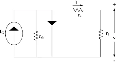
The photovoltaic system is the system which uses the sun light to generate the electrical energy by the photoelectric phenomenon. This phenomenon converts the solar energy (photo) into electric energy without any mechanism. The general photovoltaic circuit module is shown in figure.1.+
-v
IG
rsh
rs
rl
I
The circuit consists of a shunt resistance
r
shconnected withthe parallel diode
D
. The current sourceI
Gindicates thesolar cell. The circuit consists of a series resistance
r
sandr
Lindicates load resistance or battery. The solar cell posses the p-n junction of a semiconductor. The generation of DC current depends upon the light irradiation. If the light is not present, then it acts as a diode and the current will not produce. If the light is present current will be generated. If the PV module is operating under normal condition, the power dissipation will take place across internal resistance and hence the efficiency will decrease. The shunt resistance
sh
r
need to be kept of infinite as it will restrict the flow of current in single direction. To avoid the further voltage drop
at the load side, the
r
s should be kept zero.It is observed that, as the temperature increases the series
resistance
r
s will increase. For better efficiency the value ofs
r
need be low. Thus the more efficiency will be observed in the colder countries than the in the desert area, as the
temperature will be low and hence the low
r
s.2.1
Connection of Panel in PV Module
The panel connection is shown fig.2. If the panel connection is in series, the voltage will be added up while in parallel connection the system voltage will be minimized or remain same.+
-+
-+
-+
-+
-+
-Series
Parallel
V 2V
A 2A
Fig 2: Shows the Panel Connection
2.2
V-I Characteristics of MPPT
The V-I characteristics of MPPT is shown in figure.3. The open circuit voltage is indicated in x-axis while y-axis indicates the short circuit current. It is observed there is a maximum power point (MPP) which is the maximum power delivered to the panel.
C
u
rr
en
t>
>
Volatage>>
Maximum Power
Point
Fig 3: Shows the V-I Characteristics of PV Module with MPPT
2.3
MPPT Design using MPPT Algorithm
The MPPT design depends on the output voltage regulation of the PV array or reference current or voltage signal. This voltage and current may be constant or may be derived from the output characteristics (power change) of PV array. The variation in the power uses the DC-DC converter duty cycle D as the control parameter, and derivative of power over dutycycle will be forced to zero, i.e.
d
(
P
)
/
d
(
D
)
0
. Hence only one loop is used in the algorithm (step.5 to step.2). Algorithm:1. Start.
2. Measure
V
andI
from the panel. 3. Calculate the powerP
VI
. 4. IfmP
0
a.
mV
0
i.
D
D
mD
Else
ii.
D
D
mD
To the MOSFET Else b.
mV
0
i.
D
D
mD
Else
ii.
D
D
mD
To the MOSFET 5. MOSFET to step 2. Here,
P
Output power of PV array.
m
Derivative
D
Duty Cycle.
mD
Perturbation.The P& O algorithm is the commonly used MPPT algorithm. The design method has duty cycle
D
which separates the panel and battery with varied small amount ofmD
.
Consider this variation is increased, the corresponding current and voltage are measured and also the change in the powermP
. The perturb direction is correct if
positive
is
mP
and the perturb is need to be continued in same direction. The direction of per tub will be reversing if
negative
is
mP
and the process will continue.The design algorithm main aim is to raise the power curve to get the maximum power output from PV module. This way PV module operates to give the maximum power. The Load connected will be constant it will not operate at MPP.
3.
TECHNIQUES DC-DC CONVERTER
ASOCIATED WITH MPPT
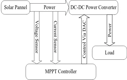
operating point changes to the module impedance. Hence during different weather condition, the module impedance can be used to match the load impedance. In this, the two different DC-DC converters like Buck converter and Boost converters with MPPT are used. Few comparisons in DC-DC such as voltage, power output current for each different combination are discussed. Multi changes in irradiance, duty cycle, and temperature by keeping current and voltage as main sensing parameter.
Solar Pannel DC-DC Power Converter
MPPT Controller
Load
V
o
lt
a
g
e
S
e
n
s
o
r
C
u
rr
e
n
t
S
e
n
s
o
r
Power
C
o
n
tr
o
l
V
ia
D
A
C
P
o
w
e
r
Fig 4: DC – DC Converter for Process at the MPP
3.1
Buck Converter
The converter in which the output voltage is lower than the input voltage, while the output current will be higher than the input current. The general circuit of the buck converter is shown in figure.5.
+
-V
in
V
m
+
-C
V
out
+
-Rout
L
Fig 5: Shows Buck Converter Circuit
Where
in
V
Input voltage.
out
V
Output Voltage.
D
Duty Cycle.The conversion ratio for the is given by the following expression
,
D
V
V
I
I
in out
out
in
(1)
Where,
D
Duty cycle
inV
Input voltage
inV
Output voltage,The above equation can be written as,
D
V
V
outin
(2)D
I
I
in
out
(3)Thus the input resistance can be calculated as,
2 2
D
R
D
I
V
D
I
D
V
R
outout out
out out
in
(4)Here,
R
out- is the output resistance.As the duty cycle
D
, varies from 0 to 1, the input resistance varies from ∞ toR
out.3.2
Boost Converter
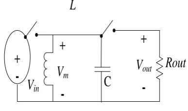
The converter in which the output voltage is higher than the input voltage, while the output current will be lower than the input current. The general circuit of the boost converter is shown in figure.6.
Where
in
V
Input Voltage.
out
V
Output Voltage.
D
Duty Cycle.+
-C
V
outRout
i
outD
T
i
Ti
LV
inL
i
D+
-Fig 6: Shows Boost Converter Circuit
The conversion ratio for the is given by the following expression
,
1
1
D
V
V
I
I
in out
out in
(4)Where,
The above equation can be written as,
)
1
(
D
V
)
1
(
D
I
I
out in
(6)Thus the input resistance can be calculated as,
2 2
)
1
(
)
1
(
1
)
1
(
D
R
I
D
V
D
I
D
V
R
out out out out outin
(7)Here,
R
out- is the output resistance.As the duty cycle
D
, varies from 0 to 1, input resistance will vary.3.3
Buck-Boost Converter
The combination of both Buck and Boost converter is known as Buck-Boost converter. The circuit is described in figure.7.
+
-V
in
V
m
+
-
C
V
out
+
-Rout
L
SW1Fig 7: Shows Buck-Boost Converter Circuit Where,
in
V
Input Voltage.
out
V
Output Voltage.
D
Duty Cycle.The conversion ratio for the is given by the following expression
,
1
D
D
V
V
I
I
in out out in
(1)The above equation can be written as,
D
D
V
V
out in)
1
(
(8))
1
(
D
D
I
I
out in
(9)Thus the input resistance can be calculated as,
2 2 2 2
)
1(
)
1(
1
)
1(
D
D
R
D
I
D
V
D
D
I
D
D
V
R
out out out out out in
(10)Here,
R
out- is the output resistance.As the duty cycle
D
, varies from 0 to 1, input resistance will vary from∞ to 0.The following table 1. Gives the comparison between the Buck, Boost and Buck-Boost converter:-
Table 1: Comparison between the Buck, Boost and Buck-Boost Converter
Converte r type /
Analysis Buck Boost Buck-Boost
in out out in
V
V
I
I
D
1
D
1
D
D
1
inV
D
V
out)
1
(
D
V
out
D
D
V
out
(
1
)
in
I
I
out
D
)
1
(
D
I
out
(
1
D
)
D
I
out
inR
2D
R
out 2)
1
(
D
R
out
2 2
)
1
(
D
D
R
out
4.
RELATED WORK
This section gives the literature review of many researchers who have worked on DC-DC converter, PV module, and MPPT.
G. Haritha et al., [3] have presented the algorithm for PV Systems based on DC-DC converter. For performance evaluation Matlab/Simulink tools were used on energy point. The outcome of the study gives the better value of output for both boosts and buck converters by producing entire converter with a different type of curves.
B Zhao et al., [4] have discussed the High frequency DC-DC converter effects like current impact and transient DC bias. The comprehensive experiments were verified with theoretical analysis. The outcome of the discussion gives clear explanation about phenomenon of transient process.
R.W. Erickson et al., [6] have discussed new technologies for the development of thin film PV cells. The Simulation system is developed to provide a description for losses. The outcome of the discuss gives the reduced cost design for building photovoltaic (PV) systems.
A. Gowaid et al., [7] have presented the topology of conventional (DAB) Dual-Active- Bridge uses over soft switching in reasonable operating range irrespective of the resonant circuit. Design and analysis of multi-level converter for high and medium voltage DC-DC transformer were discussed. The outcome of the study gives efficient multi-level converter design.
M. Huemer et al., [8] have illustrated the DC-DC converter operation in variable switching frequencies. The experimental results were obtained by using simple integrated circuit (SIC) with a controller. The outcomes of the study give the modeling approach for a wide range of applications of DC-DC converter.
A.H.El. Khateb et al., [9] have presented MPPT (Maximum Peak Power Converter) for battery charging. The discuss uses the two signals (one for MPPT and another for battery charging).The converter effectiveness is tested in various operating condition using Simulation. The outcome of the study gives the battery with longer time battery life charger.
S.N. Begam et al., [10] have given Photovoltaic (PV) system using DC-DC converter by using delta conversion concept. The presentation uses SEPIC (Single Ended Primary Inductor Converter) as delta converter or DC-DC converter, and the simulation results were found using MATLAB. The outcome of discussing gives the novel module DC-DC, SEPIC converter with improved voltage results.
M. Kasper et al., [11] have discussed many concepts for DC-DC converter of photovoltaic panel integrated. The measurement of high-efficiency results of the experimental prototype was compared with commercial MIC. The outcome of the study gives the much wider prototype than a commercial converter, with more efficiency.
A. M. Abusorrah et al., [12] have presented boost converter stability fed from PV (Photovoltaic) source. Many converter topologies were used to connect the sources and grid, but most of the parts were used are of DC-DC converter. The Simulation results were observed by the reference current, load resistance, photo current, time, and voltage, etc. The outcome of the study gives the good dynamic feature from non-linear and theory circuit view point.
5.
EXISTING SYETEM
5.1
Hill Climbing Approach
The Hill climbing method uses (P & O) algorithm, in PV module and MPPT technique because of its effectiveness and it is anything but difficult to execute and it needn't bother with an earlier modeling source. The essential rule about the hill climbing is that the voltage is persistently being disconnected, and the power is seen to figure out whether it is expanding or decreasing in like manner. P & O techniques are two distinct approaches to performing the same fundamental techniques. Hill climbing and P&O strategies can fall flat under quickly changing environmental conditions as outlined in figure 8. Beginning from an operation point A, the i.e. P1 arc is used, if climatic conditions stay more or less steady, a perturbation ΔV in the PV voltage V will pass on the working point to
point B and thus the bothering will be pivoted due to a decreasing in power.
P
P2
P1
A C
B
V V+ΔV
Fig 8: Divergence of Hill Climbing/P&O from MPP
Daoud et.al [13] author explained the study of sensor based MPPT method for Photovoltaic water pumping model. In this, a traditional hill climbing technique also applied to track MPP, utilizing the data obtained from voltage nodes.
Tuffaha et.al [14] also gives the studies of different hill claiming MPPT techniques and observed that the modification has been performed. And this paper also verifies the tracking calculations. The simulation is done using Matlab and Simulink.
5.2
Fuzzy Logic Control
The Fuzzy Logical controllers have the benefits of working with uncertain inputs, not requiring an exact numerical model, and taking care of nonlinearity. It uses the fuzzy logics to settle on the choices and to control the yield of the controller. Fuzzy Logic control, by and large, comprises of three stages: Fuzzification, principle defuzzification, and a base lookup table. Through fuzzification and numerical information, variables are changed over into phonetic variables in light of an enrolment capacity. For this situation, five Fuzzy levels are utilized: NB (negative huge), NS (negative little), ZE (zero), PS (positive little), and PB (positive enormous). The components of fuzzy logic based MPPT shown in figure 9. There are two types of inputs to the control the error “e (k)” and modify in error “Δe (k)”. The Fuzzification square changes over the fresh inputs to fuzzy inputs. The rules framed in principle base and are connected in derivation block. The defuzzification changes over the fuzzy yield to the fresh yield.
F
u
z
z
i
f
i
c
a
t
i
o
n
Rule Base
Inference
De
f
u
z
z
i
f
i
c
a
t
i
o
n
e(k)
Δe(k)
Δu(k)
Fig 9: Fuzzy Logic Block Diagram
MPPT techniques for PV models. It has mainly two membership functions to improve the effectiveness of FLC-based methods. And the author also gave the comparison of above methods, and it will improve the transient period and MPPT tracking rate by 25.8% and 0.98% under STC, respectively. Takun et.al [16] proposed an FLC technique to control the MPPT for PV models. It utilizes the fuzzy logical method to analyze the size of improved current in the MPPT. As the results show, the convergence period of MPTT of novel method is very much better than the P&O methods.
5.3
Ripple Correlation Control
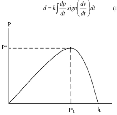
The sign ripple is available in the power converters. The ripple correlation control (RCC) associates the varieties of force with voltage or current as for time and the time derivative of power merges to zero. The ripple is an element of perturbation, gradient ascent optimization to track the MPP. The features of RCC are that the system meets asymptotically rapidly to the MPP, and require the estimation of the PV exhibit parameters. This procedure is less expensive and suited for particular applications. The RCC methods force the module current IL to track the MPP current IL* as demonstrated in Figure. 9. The disadvantage of RCC is that it can't be utilized for DC loads, three stage loads or noisy single stage loads. The comparison that controls the obligation cycle can be composed as:
dt
dt
dv
sign
dt
dp
k
d
.
(11)P
P*
I*
LI
LFig 10: PV Array Average Power vs Average Inductor Current
Where k is the positive increase consistent. The above Equation joins to a point nearer to the MPP. Convergence rate can be extended by use high controller gain. At the same time, a bigger inductor would be important to decrease the voltage and energy ripple. If gain and ripple are very high, the control can immerse and show the point of confinement cycle conduct. RCC is more qualified for secluded frameworks, where each PV exhibit is associated with its MPP tracker unit. Savenkov et.al [17] have been designed and fabricated a very low-cost MPPT, it will be using an RCC method. RCC well-grounded along with it is suited for PV applications. It shows that when the changes in the temperature or sun illumination occur, a rapid shift will occur, and it will update the MPP. It has a convergence period in the order of milliseconds, and a very high level of tracking effectiveness.
5.4
DC Link Capacitor Droop Control
It resolve be in the order of the MPPT method is suitable for PV arrangement associated in parallel with an AC arrangement as demonstrated in Figure. The ratio of the duty cycle to the boost converter is explained in below equation,link
V
V
d
1
(12) In the above equation, V is voltage over the PV arrays and Vlink is the voltage over the dc link. The duty cycle "d" is streamlined to make Ipeak most extreme by avoiding voltage drop of Vlink. This procedure has the point of preference that it doesn't require the calculating of PV group power and the control plan is effectively actualized with operational enhancers and logical units. Adhikari et.al [18] presents the evaluation of P&O and DC link capacitor droop control methods for PV module using Matlab and Simulink tools. This MPPT method was implemented, and it will compare with its performance evaluations. Results are compared with other techniques, to verify the working methodology, functionality, and reliability of MPPT techniques for standalone.PV Array
v
Boost Converter
MPPT Control
I N V E R T E R DC
Link AC System
Line
Vlink
Ipeak
Fig 11: Topology for DC Link Capacitor Droop Control
5.5
Load I or V Maximization
The reason for MPPT procedures is to amplify the power leaving a PV array. At the point when the PV exhibit is associated with a power converter, boosting the PV array power amplifies the results power at the heap of the converter. Then again, boosting the yield power of the converter should be open up the PV show force, tolerating a lossless converter. Most loads can be of voltage source strategy, current-source technique, resistive sort or a blend of these, as exhibited in Figure 12. From this figure, it is clear that for a voltage-source sort stack, the heap current iout ought to be extended to
accomplish the most compelling yield power PM. For a present source sort stack, the heap voltage vout ought to be opened up.
i
outP1<P2<PM
v
outFig 12: Different Load Types
5.6
β Method
In this strategy a consistent called beta (β) is given, the estimation of β is given by the equation,
Vpv
T
k
q
Vpv
lpv
ln
(13)Where "k" is Boltzmann's consistent, "η" is quality diode component, "T" is surrounding temperature in Kelvin and "q" is an electric charge. It is clear from above mathematical statement β is free from the powered solar radiation, however, relies on upon the temperature. In this system, the solar oriented PV works close to this quality β. Merit: Tracking velocity is high. Demerit: Applicable for changing solar oriented radiation, however, the temperature should be constant.
5.7
Fractional Voc
Fractional Open-Circuit Voltage The close straight relationship in the middle of and of the PV cluster, under changing irradiance and temperature levels, has offered ascent to the fragmentary technique. , where is a steady of proportionality. Since is subject to the qualities of the PV cluster being utilized, it, for the most part, must be registered previously by observationally deciding, “And” for the exacting PV exhibit at characteristic irradiance and temperature stage. The component has been accounted for to be somewhere around 0.71 and 0.78. The technique does not need any input. It is significant to monitor that when the PV panel is in low lagging conditions, the method is more successful. Detailed algorithm of is represents below, Step1: Start.
Step2: Measure the open circuit voltage
V
ocand choose valueof
K
1Step3: Calculate the MPP operating voltage as,
oc
m
K
V
V
1
Step4: Compare
V
m with panel voltageV
p Ifp
m
V
V
Then stop ElseChange the value of
K
1 Step5: Repeat the step 1-4.Esram et al. [19] have introduced a Comparison of Photovoltaic Array Maximum Power Point Tracking Techniques. The authors have discussed the many dismillar methods for highest power point tracking of photovoltaic (PV) arrays are presented. The methods are taken from the literature dating back to the initial techniques. This greatly depends on the end-users’ knowledge. Some might be more familiar with analog circuitry, in which case, fractional ISC or VOC, RCC, and load current or voltage maximization are good options. Kumari et al. [20] have introduced a Comparison of MPPT Algorithms for PV System. The authors have discussed the Isc technique is multipart and costly when to compare to Voc. However, the Isc technique gives very high efficiencies about 96% and performs well with changing radiation and temperature.
5.8
Fractional Isc
FSCC is an unsophisticated but a swift technique of tracking the MPP. To track the power, this MPPT technique requires the value of SCC by isolating the PV array. The MPPT calculated using this technique is based on Eq. which is an approximation; hence, this method does not operate on true MPPT. Nevertheless, the simplicity of this technique makes it suitable for use in small scale cheap applications. This method is suitable to be implemented by using either the analog or the digital mode. The basic outline of this technique follows that the current at MPP (
I
m) is closely located near the shortcircuit current
I
SC. Therefore, the operating point can bereached by multiplying
I
SC by the factorK
1 as givenbelow:
I
m
K
1
I
SC. , here theK
1varies from 0.71 and 0.92. The detailed algorithm is explained below.Step1: Start.
Step2: Measure the short circuit current
I
SCand choosevalue of
K
1Step3: Calculate the MPP operating current as,
SC
m
K
I
I
1
Step4: Compare
I
m with panel currentI
pIf
p
m
I
I
then stopElse
Change the value of
K
1Step5: Repeat the step 1-4.
Sher et al. [21] have introduced an intelligent control strategy of fractional short circuit current MPPT technique for PV applications. The authors have discussed modification intelligently calculates the right time to isolate the PV panel, thus does not need the time-based measurement of short-circuit current.
a focus on the comparison of two different converters that will connect with the controller. One straightforward sun oriented board that has a standard estimation of protection and temperature has been incorporated in the reproduction circuit.
5.9
Current Sweep
The current sweep method manipulates the solar panel current, so during the current sweep, there will be reduced power output. The current sweep determines the i-v feature of the PV and the MPP voltage is determined. The controller holds this computed voltage as the operating voltage of the solar panel until the next current sweep determines a new maximum power point voltage. So, the current sweep is not performed continuously, but only periodical. It only makes sense to perform a current sweep if the increase in generated power is greater than the loss of power by performing the current sweep. This is the main consideration for determining the period of the current sweep method. The solution of the differential equation for f (t) is unique and equals to f (t) = c ∗
e t k. In this method, the I-V characteristic curve is obtained using a current sweep waveform by PV array. The sweep is repeated at fixed time intervals, so the I-V curve is updated periodically and the MPP voltage (VMPP) can be determined from it at these same intervals. In instances of two peaks in the power, the sweep quests to take after the most noteworthy as demonstrated in Figure 13. The MPP flow range hunt is a bit much in ordinary conditions. The current sweep takes around 50 ms, suggesting some loss of accessible force. This MPPT technique just achievable if the force utilization of the following part is lesser than the increase in energy so as to it can convey to the whole PV system.
P
I
Fig13: Multiple Maxima under Partial Shading Condition
Popovic et al. [23] have introduced Maximum Power Point Tracking: Algorithm and Software Development. The authors have verified that the controller and the implemented algorithms work correctly. After adding filters and buffers to the ADC inputs, the controller was able to track the MPP reliably.
Goudar et al. [24] have an assessment of enhanced Maximum Peak Power Tracking Algorithms for PV. The authors focus PV Array at peak power for enhanced effectiveness, typical I-V feature of a “crystalline silicon” module, the unlikeness of energy against voltage beside with the spot of MPP is as a purpose of irradiance and temperature.
5.10
dP/dV or dP/dI Feedback Control
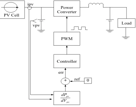
General characteristics of the dP/dV feedback-controlled MPPT method, with DSP and microcontroller being able to handle complex computations, an obvious way of performing MPPT is to compute the slope (dP/dV or dP/dI) of the PVpower curve and feed it back to the power converter with some control to drive it to zero. In, dP/dV is computed, and its sign is stored for the past few cycles. Based on these signs, the duty ratio of the power converter is either incremented or decremented to reach the MPP. The linearization-based method is used to compute dP/dV. In sampling and data, conversion is used with the subsequent digital division of power and voltage to approximate dP/dV, dP/dI am then integrated together with an adaptive gain to improve the transient response. In the PV array voltage is periodically incremented or decremented and ΔP/ΔV is compared to a marginal error until the MPP is reached. Convergence to the MPP was shown to occur in tens of milliseconds. A typical characteristic curve for PV cells in which the dP/dV ratio is zero at the MPP under any insulation or temperature condition. Positioning the dP/dV=0 on the PV cell power-voltage curve in can be implemented by tracking the MPP with the help of the dP/dV slope control loop as shown in below Fig 14.
Power Converter
PWM
Controller
pv pv
dV dP
+ 0
err
ref
Load vpv
ipv
PV Cell
Fig 14: Functional Blocks of a “dP/dV Feedback-Controlled MPPT” System
Park et al. [25] have set up a “dP/dV Feedback-Controlled MPPT Method for Photovoltaic Power System Using II-SEPIC. The authors suggest that technique through straight dP/dV value feedback and bring to PV energy generation systems customized dynamic reaction with the assist of a current-mode dP/dV feedback-controlled MPPT technique.
Singh et al. [26] have introduced Comparison of Photovoltaic Array Maximum Power Point Tracking Techniques. The authors have discussed Solar cell operates at very low efficiency and thus a better control mechanism is required to increase the efficiency of the solar cell. In this field, researchers have developed what are now called the MPPT algorithms.
5.11
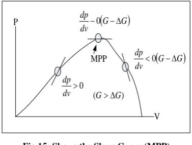
Increment Inductunce(IC) Approach
The observations are represented in Fig.15. Where, the slope of power curve =dP/dV. It is seen that within the operating limits, the PV module power output increases with increase in terminal voltage (dP/dV >0, the slope is positive). In another hand, at some past operating point, the PV module output power will decreases with increase in the terminal voltage (dP/dV <0, the slope is negative). When the operating point is exactly at the MPP, the angle of the curve as expected is zero. At the operating point exact to MPP (dP/dV=0; the slope is expected to zero).
P
V 0
dv dp
) (GG
MPP
G G
dv
dp
0
G G
dv
dp
0
Fig 15: Shows the Slope Curve (MPP)
Fig.15 shows the power curves and the slope at the MPP (maximum power point). Several researchers have studied on the incremental inductance of Maximum Power Point Tracking (MPPT); few of them are discussed below.
M.H Saied et al. [27] have presented a survey of several MPPT techniques used in PV (Photo voltaic) power systems. The outcome of the study gives convenient reference to power generation in PV for future.
S Ghosh et al. [28] have discussed the MPPT observation on solar power grid with efficiency using Matlab/Simulink. The outcome of the discussion gives extended implementation to other MPPT algorithms.
J.H Lee et al. [29] have given an advanced MPPT (Incremental conductance) algorithm. The outcome of the study gives faster and robust MPPT algorithm. A Safari et al. [30] have presented an incremental conductance method for MPPT with DC-DC, cuk converter. The presented study gives the outcome of high speed, accurate and exploitation for full utilization of modules (photovoltaic).
T Radjai et al. [31] have presented the classic increment conductance Maximum Power Point Tracking (MPPT) algorithm. In the study algorithms were implemented digitally on d-SPACE, ACE1104 platform after Simulation studies. The outcome of the study gives efficient & well-designed converters to overcome disadvantages of IC.
5.12
Nueral Network Approach
The Neural network architecture is used to find the extracts solution for random variable once, complex systems or non-linear systems. Among all its types, the useful, more important and widespread is back propagation network. The results and functions of an ANN (Artificial Neural Network) were determined by different kinds by using its architecture. The fig.16 shows the speed generated neural network topology [32].
Input Layer
Hidden Layer
An Activation
Function
The Direction of
the Data Flow Output
Layer
Fig 16: Shows Neural Network Topology
The bias signal is connected to the network is connected and coupled to all the neurons (hidden layer) through weight (W).The ANN topology uses multilayer type perception network consists of an output layer, an input layer and a hidden layer with a transfer function of sigmoid type. The neural network uses two neurons as input (X1 & X2), one for ambient temperature (a1, a2, a3, a4 & a5) and other for the radiation f(a1), f (a2), f a3, f a4 & f a5), which is arranged and then the pulse neurons in hidden layers. A neuron at the output layer for DC/AC frequency control.
A.B.G. Bhagat et al. [33] have presented an implementation and development of a computer-based MPPT (Maximum Power Point Tracking) using a neural network for PV (Photo Voltaic) Systems. The system was implemented and tested in various conditions. The outcomes of the study give results with the help of MPPT for PV (operation in different conditions.
J.N. Reddy et al. [34], have given a neural network application for PV modules, which depend on environmental conditions like cell temperature and solar insulation and many. This model is simulated using Matlab/ Simulink to get the results. The outcome of the study gives the accurate result over seasonal variations.
M.A. Sahnoun et al. [35] have given an optimization control of P& O MPPT with the help of neural network algorithm. The algorithm is applied on different kinds of solar panels and is validated experimentally. The outcome of the discuss gives the reduction of complexity and accuracy improvement of MPPT. D Vasarevicius et al [36] discussed the application of ANN (Artificial Neural Network) for MPPT of Photovoltaic (PV) Panel. The Mathematical system model is subjected to Matlab/Simulink the outcome of the study gives efficient MPPT using ANN (99%).
6.
RESEARCH GAP
force converter that can differ the present originating from the PV array.
Current sweep is not performed continuously, but only periodical. It only makes sense to perform a current sweep if the increase in generated power is greater than the loss of power by performing the current sweep. Load I or V Maximization method cannot be implemented easily with digital operational, and decision making not possible with true MPPT. Fuzzy Logic Control is not able to take an analog decision as well as varies in sensed parameters.
Hill climb probing algorithm all algorithms mentioned have irregular behavior in case of rapidly changing irradiation conditions, it is possible the algorithm lost track of the MPP and reduced power output will occur.
Ripple Correlation Control (RCC) the photovoltaic array are not dependent on it also not generate digital process and implementations complexity is low.
7.
CONCLUSION
This paper has talked about the harvest proficiency difficulties of incomplete PV cluster shading. Schneider Electric's shade-tolerant string inverter methodology is indicated to unravel a portion of the difficulties confronted when acquiring most extreme harvest productivity of shaded module clusters with nearby greatest force "knocks" on their I-V curve. We have found in this study in detail the reenactment of two routines for control: perturb and observe (P&O) and fuzzy controllers, the two were connected on a chain of vitality transformation supplied by Boost converter. We thought about the got reenactment results, by subjecting the controlled framework to the same natural conditions. We can infer that MPPT fuzzy controller is given the experience of the administrator. It has a decent execution. It enhances the reactions of the photovoltaic framework, it not just lessens the time because of the proceeded with most extreme force point however it likewise disposes of the changes around this point. The way that demonstrates the adequacy of a fuzzy controller for photovoltaic frameworks in standard as in variable ecological conditions. The outcomes acquired for this vitality transformation framework, demonstrate that by utilizing the MPPT fuzzy controller, there is a tradeoff between quickness in transient administration and solidness in the unfaltering state. These utilized controllers results can be contrasted with different techniques for control as utilizing neural systems as a part of upgrading the photovoltaic generator control, the thought of our future fill in as an expansion of our exploration to enhance more the PV frameworks yield.
8.
REFERENCES
[1] M. S. Sivagamasundari, P. Melba Mary, and V. K. Velvizhi. "Maximum Power Point Tracking For Photovoltaic System by Perturb and Observe Method Using Buck Boost Converter." International Journal of Advanced Research in Electrical, Electronics and Instrumentation Engineering, Vol 2, No. 6, PP.2433-2439, 2013.
[2] D. Choudhary1, A. R. Saxena,"DC-DC Buck Converter for MPPT of PV System”, International Journal of Emerging Technology and Advanced Engineering, Volume 4, Issue 7, PP. 813-821July 2014.
[3] G.Haritha, A.Pradeep Kumar Yadav, S.Thirumaliah, “Comparison of MPPT Algorithms for
DC-DCConverters Based PV Systems”, International Journal of Advanced Research in Electrical, Electronics and Instrumentation Engineering, Vol. 1, Page 1, July 2012.
[4] B. Zhao, Qiang Song, Wenhua Liu, and Yuming Zhao, “Transient DC Bias and Current Impact Effects of High-Frequency-Isolated Bidirectional DC-DC Converter in Practice”, IEEE Transactions Power Electronics, 2015.
[5] Y Shi, Rui Li, YaosuoXue, Hui Li,” Optimized Operation of Current-Fed Dual Active Bridge DC-DC Converter for PV Applications”, IEEE Transactions Industrial Electronics, February 10, 2015.
[6] Robert W. Erickson, Aaron P. Rogers, “A Microinverter for Building-Integrated Photovoltaics”, IEEE, 2009. [7] I. A. Gowaid, Grain P. Adam, Shehab Ahmed, Derrick
Holliday, and Barry W. Williams, “Analysis and Design of a Modular Multilevel Converter with Trapezoidal Modulation for Medium and High Voltage DC-DC Transformers”, IEEE Transactions Power Electronics, Vol. 30, pp.10, 2015.
[8] Mario Huemer,Robert Priewasser, Matteo Agostinelli, Christoph Unterrieder, and Stefano Marsili, “Modeling, Control, and Implementation of DC–DC Converters for Variable Frequency Operation”,IEEE Transactions Power Electronics, Vol. 29, Page. No1, 2014.
[9] A. H. El Khateb, NasrudinAbd Rahim, and JeyrajSelvaraj, “Cuk-Buck Converter for Standalone Photovoltaic System”, Journal of Clean Energy Technologies, Vol. 1, Page. No. 1, January 2013. [10]S. N. Begam, and Dr. SP. Umayal, “PV System Using
DC-DC Converter In A Delta Conversion Concept”, International Journal of Emerging Technology and Advanced Engineering,Volume 3, Page. No.5, May 2013.
[11]M Kasper, Dominik Bortis, Thomas Friedli and Johann W. Kolar, “Classification and Comparative Evaluation of PV Panel Integrated DC-DC Converter Concepts”, 15th IEEE International Power Electronics and Motion Control Conference (ECCE Europe 2012), Novi Sad, Serbia, 2012.
[12]Abdullah Abusorrah, Mohammed M. Al-Hindawi, Yusuf Al-Turki, Kuntal Mandal Damian Giaouris,Soumitro Banerjee, Spyros Voutetakis, SimiraPapadopoulou,“Stability of a boost converter fed from photovoltaic source”, Elsevier solar energy, Vol 98, pp. 458-471, 2013.
[13]A. Daoud and A. Midoun, “Maximum power point tracking techniques for solar water pumping systems”, Revue des Energies Renouvelables Vol. 13 N°3 (2010) 497 – 507.
[14]T.H. Tuffaha, M. Babar, Y. Khan and N.H. Malik, “Comparative Study of Different Hill Climbing MPPT through Simulation and Experimental Test Bed”, Research Journal of Applied Sciences, Engineering and Technology 7(20): 4258-4263, 2014.
[16]Pongsakor Takun, Somyot Kaitwanidvilai and Chaiyan Jettanasen, “Maximum Power Point Tracking using Fuzzy Logic Control for Photovoltaic Systems”, Proceedings of the International Multiconference of Engineers and Computer Scientists (IMECS), 2011
[17]M. Savenkov & R. Gobey, "A Simple Maximum Power Point Tracker Utilizing the Ripple Correlation Control Technique", ISES-AP - 3rd International Solar Energy Society Conference – Asia Pacific Region (ISES-AP-08) Incorporating the 46th ANZSES Conference, 2008
[18]S.Adhikari and F. Li, " Coordinated V-f and P-Q Control of Solar Photovoltaic Generators With MPPT and Battery Storage in Microgrids", IEEE Transactions on Smart Grid, Vol.. 5, No. 3, 2014.
[19]T. Esram and P. L. Chapman. "Comparison of photovoltaic array maximum power point tracking techniques." IEEE Transactions on Energy Conversion, Vol 22, No. 2,pp 439-449, 2007.
[20]J. S. Kumari and C.S. Babu. "Comparison of maximum power point tracking algorithms for photovoltaic system." International Journal of Advances in Engineering & Technology, Vol 1, No. 5 ,PP 133-148,2011.
[21]H. A. Sher, A. F. Murtaza, A. Noman, K. E. Addoweesh, and M. Chiaberge. "An intelligent control strategy of fractional short circuit current maximum power point tracking technique for photovoltaic applications." Journal of Renewable and Sustainable Energy ,Vol 7, No. 1,2015 [22]C. H. Kumar, T. Dinesh, and S. G. Babu. "Design and Modelling of PV system and Different MPPT algorithms." International Journal of Engineering Trends and Technology (IJETT), Vol 4, No. 9 ,PP 4104-4112,2013.
[23]S. Moring,, and A. F. Popovic, "Maximum power point tracking: algorithm and software development",Delft University of Technology Faculty of EEMCS, 2012. [24]M. D. Goudar, B. P. Patil, and V. Kumar. "A review of
improved maximum peak power tracking algorithms for photovoltaic systems." International Journal of Electrical Engineering, Vol 1, PP 85-107, 2010.
[25]H. E. Park and J.H. Song. "A dP/dV feedback-controlled MPPT method for photovoltaic power system using II-SEPIC." Journal of Power Electronics, Vol 9, No. 4, PP 604-611,2009.
[26]P. Singh, D. K. Palwalia, Amit Gupta, and Prakash Kumar. "Comparison of Photovoltaic Array Maximum Power Point Tracking Techniques",International Advanced Research Journal in Science, Engineering and
Technology,Vol. 2, No. 1, April 2015.
[27]A. N. A. Ali, M. H. Saied, M. Z. Mostafa, and T. M. Abdel-Moneim. "A survey of maximum PPT techniques of PV systems", Faculty of Engineering, Alexandria University, 2012.
[28]S. Ghosh, and V. Mahendran. "Incremental Conductance MPPT Method For Photovoltaic System",Dr. MGR Educational and Research Institute,Vol. 3, Issue 4, PP.2363-2366,Jul-Aug 2013.
[29]J. H. Lee , H. Bae and B. H. Cho. "Advanced incremental conductance MPPT algorithm with a variable step size." In Power Electronics and Motion Control Conference, 12th International, pp. 603-607, 2006.
[30]A. Safari and S. Mekhilef. "Incremental conductance MPPT method for PV systems." In Electrical and computer engineering, 24th Canadian Conference, pp.345-347, 2011.
[31]T. Radjai, L. Rahmani, S. Mekhilef, and J. P. Gaubert. "Implementation of a modified incremental conductance MPPT algorithm with direct control based on a fuzzy duty cycle change estimator using dSPACE." Department of Electrical Engineering, Malaysia,PP.325-337,2014.
[32]M. Yaichi, M. K.Fellah, and A. Mammeri. "A Neural Network Based MPPT Technique Controller for Photovoltaic Pumping System." International Journal of Power Electronics and Drive Systems,Vol 4, No. 2,PP. 241-255,2014.
[33]A. B. G. Bhagat, N. H. Helwa, G. E. Ahmad, and E. T. El Shenawy. "Maximum power point traking controller for PV systems using neural networks." Electrical Power Engineering, Faculty of Engineering, Cairo University, Vol 30, No. 8 ,PP. 1257-1268,2005.
[34]J. N. Reddy, B. M. Manjunatha, and M. Matam. "Improving efficiency of Photovoltaic System with Neural Network Based MPPT Connected To DC Shunt Motor",International Journal of Modern Engineering Research,Vol. 3, No. 5,PP. 901-2907,2013.
[35]M. A. Sahnouna, H. M. R. Ugaldea, J. C. Carmonaa, J. Gomanda,"Maximum power point tracking using P&O control optimized by a neural network approach: a good compromise between accuracy and complexity",The Mediterranean Green Energy Forum,2013.