Determination of Submergence Depth to Avoid Vortices
at Horizontal Intake Applying Flow-3D Software
Hassan Ahmadi1, Erfan Razavi2,*
1
Azad University, Roudehen Branch, Assistant Professor Civil Engineering, Iran 2
Azad University, Roudehen Branch, MSc Hydraulic Structure and Civil Engineering, Iran
Abstract
Free surface vortices is considered as one of the problems of the industry in part of flood control (over flow), agriculture, electricity and water supply plants that researchers’ effort in this way represents importance of this issue., it can cause excessive vibration, efficiency loss, structural damage, and also flow reduction in hydro turbines, pumps, Culverts and also can be potential risk and damage factor on the safety of power plants. The most important reasons for using the software FLOW 3D in this thesis is the exact study of intake and making connection between software model and Experimental model. Since software has capability to present velocity distribution in line X Y Z and other hydraulic parameters in point of Critical depth (the first depth into that vortex is not formed). In this thesis presented the Numerical model of horizontal intake with a Plexiglas Reservoir by length and width of 3.1 m and depth of 2.2 m and intake pipes with a radius of 0.3, 0.25, 0.194, 0.144, 0.1, 0.05 m and length of 3 m in determining the required depth of flooding to prevent vortex as software modeling. The results of this study can be used to derive a scrutiny relationship between the depth of flooding in the form of equations of first grade and second grade point. This relationship has been extracted after examining the application output and experimental data in terms of depth flood submergence depth (critical depth), intake diameter, Froude number, the Weber number and Reynolds number.Keywords
Critical Submergence, Free Vortex, Horizontal intakes, Numerical modelling Include1. Introduction
In modern world, water demand increases more and more due to exhausting of natural water Resources. Consequently, they should be used more carefully and efficiently due to the possibility of Facing with problems in the future. Since water is transmitted from seas, lakes, rivers or simply Reservoirs through intakes to be used in power generation, irrigation, domestic and industrial supply, Improvements in the design criteria of the intakes have a great importance to minimize cost and to Use water efficiently. As well as, performance of power plants is face by many difficult and problems. One of the major problems encountered during intake design is the specification of submergence and other design parameters in order to avoid strong free surface vortex formation. Also, electricity production and water demand are arguably two most critical issues of humanity. Collection of water for energy is managed by intakes in reservoirs. Design criteria and economical restrictions may
* Corresponding author:
[email protected] (Erfan Razavi) Published online at http://journal.sapub.org/jce
Copyright©2018The Author(s).PublishedbyScientific&AcademicPublishing This work is licensed under the Creative Commons Attribution International License (CC BY). http://creativecommons.org/licenses/by/4.0/
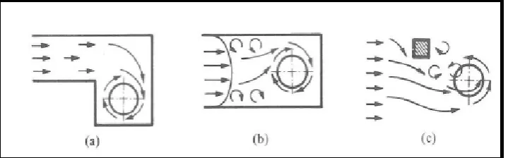
force the designer to end up with intake designs that display undesirable flow conditions, such as vortex. Vortices may be formed due to several reasons, however three main categories were pointed out by Durgin & Hecker (1978) (Guidelines for Design of Intakes For Hydraulic Plants, 1995- Figure.1). The categories are: a) Eccentric orientation of the intake b) Viscous induced velocity gradients c) Formations of eddies by obstructions.
intake structures has a definite effect on the design criteria and equipment. Thus, the location and direction of the intake should be so arranged and the water level should be well above the intake to prevent the occurrence of air entraining Vortices under the most critical scenarios (when the reservoir is at dead or minimum Storage level.). However, to reduce the cost of construction, the intake must be placed close to the Water surface as much as possible. Therefore, a design problem arises between reducing the cost and increasing the usable water capacity at the reservoir. Consequently, vortex formation at intakes should be researched continuously to obtain better optimization between them. The Concept of Critical Submergence is Vertical distance between the free surface and the intake. [3] In this paper, the aim is to extract scrutiny equation to
improve achieving the exact design guidance. The air-entraining vortex formation problems are presented here: Head losses, Generation of vibration and noise on the hydro machine, Cavitation Reduction in discharging capacity, Dam overflowing, Decrease in efficiency of pumps, Increase in wearing rate, Increase in the maintenance costs [3]. Prevent vortex formation: Increasing roughness in the rigid boundaries, Designing the geometry of the intake zone as streamlined approach to the inlet with small curvature, Slopping the floor gradually from the base to the level of the inlet for the case of projection of inlet from the base Floating raft from the base Baffle wall. On this account, classification of free surface vortices at intakes are shown in fig 2.
Figure 1. Causes of Vortices (Durgin & Hecker 1978)
2. Literature Review
Anwar [4], [5], [6] worked experimentally and theoretically on a steady vortex with an air core at the entrance of an outlet pipe and also on solutions to suppress vortex formation.
Blasdell and Donnelly [7] carried out a study in order to investigate the use of hood inlet since this type inlet is simple, economical, and can be easily installed for agricultural purposes. The hood inlet is formed by cutting a pipe at an angle and it is placed such that the longer part is at the top. During experiments on the hood inlet, a number of different types of vortex inhibitors were tested in order to prevent vortex formation at the inlet. Jain et al. [11] conducted experiments with two geometrically similar cylindrical tanks by placing vertically oriented intake pipe at the center of the bottom boundary of the tanks. The critical submergence ratio was found to be a function of the Froude number in the following form from the experimental data which are valid for the range of Froude number; 1.1 ≤ Fr ≤ 20. Gordon [9] has concluded that it is hard to investigate the effect of the geometry on formation of vortices. Therefore, it was decided to focus on other parameters which affect the vortex formation. According to the available data, the following formulas were derived to find the critical submergence ratio:
SC/Di= 1.70Fr = 0.47
For symmetrical approach flow conditions and, Sc/Di= 2.27Fr
In fact, the extracted equation in this paper is much more comprehensive compared to the above equations. Moreover, it contain various parameters of the flow, for instance, weber, Reynolds and Froude numbers.
Yıldırım [13], [14], [15], [16] et al. (2009) investigated the effects of dimensions and relative positions of two (dual) Vertical and horizontal intake pipes on the critical submergence. As a result of experiments, the critical submergence of the dual intakes is larger than a single intake pipes because in dual pipe system.
3. Numerical Modeling
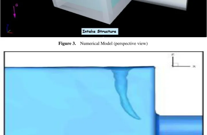
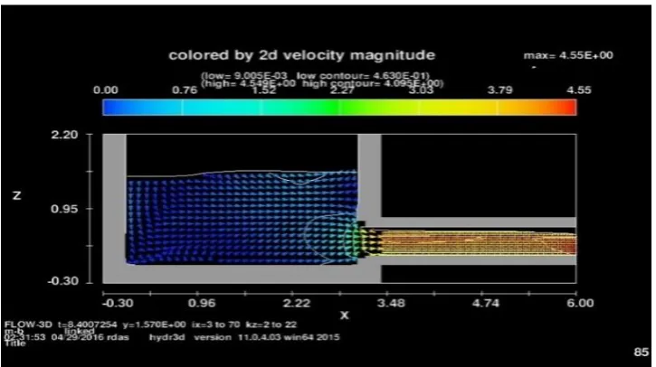
Figure of Comparisons of Vorticity Contours for Grid Dependency and Coarse mesh out of plane vorticity contour of Horizontal intake Vortex on a side plane close to free surface as well as velocity magnitude are presented (Fig 3 and Fig 4).
Figure 3. Numerical Model (perspective view)
Numerical modeling were designed to find out the importance of following settings: Submergence level of the intake, location and surroundings of the intake, and the Downstream velocity inside the intake.
Vortex is obviously seen in both mesh sizes where the
strength of the vortices are comparable. Coarser mesh ended up with a very acceptable result so there is no need to further refine mesh and increase the difficulty that already exists due to the time and computer constraints.
Figure 5a. Vorticity magnitude contours in Critical submergence depth
Figure 5b. Vorticity magnitude contours in Critical submergence depth
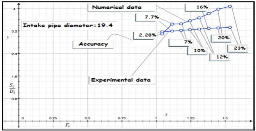
In this paper, the number of grid points for the models varies from 300.000 to 1.100.000, and the number of grids for the prototypes varies from 3.000.000 to 4.400.000 depending on the sidewall clearance b and flow depth h. Figure 5.a and 5.b shows the grid of the model case that has mesh size of 0.1 for outer and mesh size of 0.07 for inner mesh blocks. It is precisely noticed that the critical submergence values obtained with numerical solution have quiet difference from the experimental ones. When LES model is used instead of laminar solution, it yields more accurate submergence values. This improvement is related to resolution of turbulence close to the walls in the LES model which was not possible in the laminar solution. Although LES is able to decrease the error to some extent; there still exists a noticeable gap between numerical and experimental results. To investigate the possible reasons of this inconsistency, vortex formations are interpreted through different comparisons.
Flow-3D is a powerful computational fluid dynamics (CFD) code, based on solving the Navier Stokes Equations. Flow-3D uses finite volume approximations of the mass, momentum and energy equations in three dimensions to analyze the complex fluid problems. It also has models for sediment transport, moving rigid bodies, flows in porous media, etc. There are five main tabs the user will go from one to another while designing the applicable model. These tabs are:
1- Navigator: This is the screen that user will see the simulation files, portfolio summary and the path of the location of the simulation files.
2- Model Setup: The flow domain is designed, the meshing is done, and the physical and the numerical parameters are entered. There are six sub tabs at model setup tab: General, Physics, Fluids, Meshing, Geometry, Output, and Numeric.
3- Simulation: This screen provides information about the progress of the simulation. Graphics related to the simulations such as time step size, pressure iteration count etc. can be examined here when needed.
4- Analyze: This tab enables the user basically to analyze the results as a text or in 1D, 2D and 3D plots. Iso surface and color variables are chosen among the options 15.
According to the object of the study. Any time interval and any part of the system can be chosen to analyze. This will save time.
5- Display: This is the screen where user will see the visual results based on the criteria chosen at the analyze tab. Taking a snapshot of the screen or making a movie is possible.
The Ali Baykara’s reservoir, shown in Figures is 3.10 m in
length and width and 2.20 m in Plexiglas intake pipes of diameters 30.0 cm, 25.0 cm, 19.4 cm, 14.4 cm, 10.0 cm and 5.0 cm were Installed to the extended dead-end for each set of experiments in this order.
4. Results
In the present study effect of Froude, weber number and diameters of pipe intake on the formation of free surface vortices at horizontal intakes were investigated numerically. The available data were analysed and equation for critical submergence was derived.
The Analysis relationship and equation presented here considers the various variables influencing the critical submergence of the intake structure. And the functional relationship (equation) can be written for Sc/Di as
Sc/Di = 0.556248+ 0.29 Fr2 + 0.0000001 Re2 -0.0000001We2
Where
Sc= critical submergence
Di= diameter of the horizontal intake Fr= Froude number
Re= Reynolds number We= Weber number
The weber number is showed:
Where the density of the fluid (kg/m3), its velocity (m/s) and surface tension (N/m)
l is its characteristic length, typically the droplet diameter (m)
The modified Weber number equals the ratio of the kinetic energy on impact to the surface energy.
And,
The Reynolds number is defined below for each case.
Where the velocity of the object relative to the fluid (m/s), the dynamic viscosity of the fluid (Pa·s or N·s/m2 or kg/ (m·s)).
l is a characteristic linear dimension, (travelled length of the fluid; hydraulic diameter when dealing with river systems) (m), the density of the fluid is in (kg/m3).
The purpose of the numerical study and obtain this relationship was to initiate development of design information to assist an intake designer in the avoidance of free surface vortices.
Figure 7a. Difference between experimental data and numerical values of Sc/Di versus rate of Froude number (Intake pipe diameter=30)
Figure 7b. Difference between experimental data and numerical values of Sc/Di versus rate of Froude number (Intake pipe diameter=25)
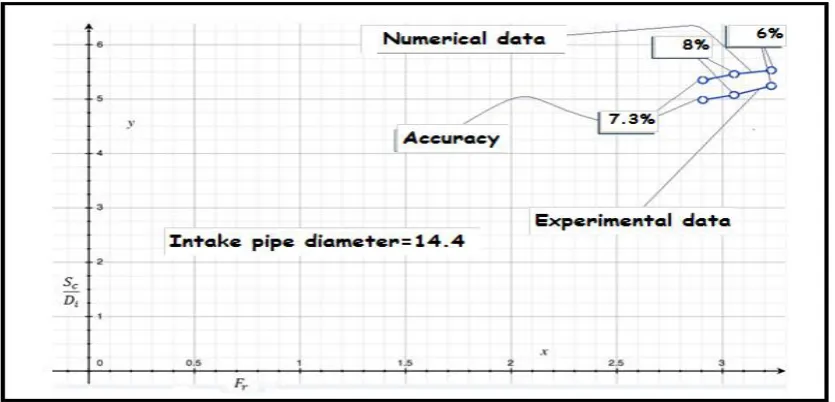
Figure 7d. Difference between experimental data and numerical values of Sc/Di versus rate of Froude number (Intake pipe diameter=14.4)
Figure 7e. Difference between experimental data and numerical values of Sc/Di versus rate of Froude number (Intake pipe diameter=10)
5. Conclusions and Recommendations
From the experimental and numerical study, the following conclusion can be drawn:
1- The purpose of the study was to compile and develop intake design criteria and calibrations model as well as functional relationship to avoid free-surface vortices at horizontal intakes.
2- Sc/Di values decrease gradually and almost linearly with increasing side walls length of an intake pipe of known diameter.
3- Sc/Di values increase gradually and almost linearly with increasing Fr, Re and We of an intake pipe of known diameter.
4- The meshing is divided into two regions: 1) a region where intake vortices are unlikely and a model study in not required expect with extremely poor approach conditions, and 2) a region with a good possibility of intake vortices, where a coarser mesh recommended.
5- Region 2, where intake vortices are a good possibility, is very large, encompassing many hydropower facilities. This is because minimum intake submergence to avoid vortex formation is highly dependent upon approach conditions, which are site specific.
6- The submergence required to avoid free-surface vortices were:
Sc/Di = 0.556248+ 0.29 Fr2 + 0.0000001 Re2 -0.0000001We2
For all the arrangements considered.
REFERENCES
[1] Ruçhan Müge Tataroğlu (2013), “Numerical investigation of Vortex formation at intake structures using flow-3d software”.
[2] Alan J. Rindels and John S. Gulliver (1983), “An Experimental Study of Critical Sub-Mergence to Avoid Free-Surface Vortices at Vertical Intakes”, University of Minesota).
[3] Ali Baykara, M.S. (2013), “Effect of Hydraulic Parameters on the Formation of Vortices at Intake Structure”, M.S. Thesis, Civil Engineering Dept., Metu.
[4] Anwar, H.O. (1965), “Flow in a Free Vortex”, Water Power 1965(4), 153-161.
[5] Anwar, H.O., Weller, J.A. and Amphlett, M.B. (1978), “Similarity of Free-Vortex at Horizontal Intake”, J. Hydraulic Res. 1978(2), 95-105.
[6] Anwar, H.O. and Amphlett, M.B. (1980), “Vortices at Vertically Inverted Intake”, J. Hydraulic Res. 1980(2), 123-134.
[7] Blaisdell F.W. and Donnelly C.A (1958), “Hydraulics of Closed Conduit Spillways Part X.: The Hood Inlet”, Tech. Paper No. 20, Series B, University of Minnesota, St. Anthony
Falls Hydraulic Laboratory.
[8] Jain, A.K., Kittur, G.R.R., and Ramachandra, J.G. (1978), “Air Entrainment in Radial Flow towards Intakes”, J. Hydraulic Div., ASCE, HY9, 1323-1329.
[9] Gordon, J.L. (1970), “Vortices at Intakes”, Water Power 1970(4), 137-138.
[10] Knauss, J. (1987), “Swirling Flow Problems at Intakes”, A.A. Balkema, Rotterdam.
[11] Padmanabhan, M. and Hecker, G.E. (1984), “Scale Effects in Pump Sump Models”, J. Hydraulic Engineering, ASCE, 110, HY11, 1540-1556.
[12] Reddy, Y.R. and Pickford, J.A. (1972), “Vortices at Intakes in Conventional Sumps”, Water Power 1972(3), 108-109 [13] Yıldırım, N. and Kocabaş, F. (1995), “Critical Submergence
for Intakes in Open Channel Flow”, J. Hydraulic Engng., ASCE, 121, HY12, 900-905.
[14] Yıldırım, N., Kocabaş, F. and Gülcan, S.C. (2000), “Flow-Boundary Effects on Critical Submergence of Intake Pipe”, J. Hydraulic Engineering. ASCE, 126, HY4, 288-297. [15] Yıldırım, N. and Kocabaş, F. (2002), “Prediction of Critical Submergence for an Intake Pipe”, J.. Hydraulic Research, 42:2, 240-250
[16] Yıldırım, N., Taştan, K. and Arslan, M.M. (2009), “Critical Submergence for Dual Pipe Intakes”, J. Hydraulic Research, 47:2, 242-249.
[17] Daggett, L.L. and Keulegan, G.H. (1974), “Similitude in Free-Surface Vortex Formations”, J. Hydraulic Div., ASCE, HY11, 1565-1581.
[18] Gulliver, J.S. and Rindels, A.J. (1983), “An Experimental Study of Critical Submergence to Avoid Free-surface Vortices at Vertical Intakes”, Project Report No: 224, University of Minnesota, St. Anthony Falls Hydraulic Laboratory.
[19] Gürbüzdal, F., (2009), “Scale effects on the formation of vortices at intake structures, M.S. Thesis, Civil Engineering Dept., METU.
[20] Jiming, M., Yuanbo, L. and Jitang, H. (2000), “Minimum Submergence before Double-Entrance Pressure Intakes”, J. Hydraulic Div., ASCE, HY10, 628-631.
[21] Li H., Chen H., Ma Z. and Zhou Y. (2008), “Experimental and Numerical Investigation of Free Surface Vortex”, J. Hydrodynamics 2008(4), 485-491. Oakdale Engineering web site, http://www.oakdaleengr.com/download.htm, last accessed on 27.10.2012.
[22] Sarkardeh, H., Zarrati, A.R., and Roshan, R. (2010), “Effect of Intake Head Wall and Trash Rack on Vortices”, J. Hydraulic Research, 48:1, 108-112.
[23] Taştan, K. and Yıldırım, N. (2010), “Effects of Dimensionless Parameters on Air-entraining.
[24] Vortices”, J. Hydraulic Research, 48:1, 57-64.