© Global Society of Scientific Research and Researchers
http://ijcjournal.org/
An Enhanced Scheduling Algorithms Framework on
Wi-Fi for Reducing Network Delay
Kones Geoffrey
a*, Dr Agnes Mindila
b, Dr Richard Rimiru
ca,b,cComputing and Information Technology (SCIT),Jomo Kenyatta University Of Agriculture And Technology
aEmail: [email protected]
bEmail: [email protected]
cEmail: [email protected]
Abstract
Wi-Fi is a modern wireless network that provides several converged integration service. Due to remarkable
growth there is a need to improve quality of service. This research focus on developing framework that
enhanced the scheduling in Wi-Fi and improving QoS so as to allocate resources based on aggregation of
frames, separation of different access categories. The problems which the Wi-Fi user’s face is delay of packets.
This research focuses on Wi-Fi IEEE 802.11n that support a high bandwidth transmission rate and aggregation
of Ethernet packets. A simulation was carried out to compare network QoS performance with and without the
proposed framework. Simulations Shows that there is reduction of delay, the change in packet size in this
Simulation control environment slightly alters the delay. There is reduction in delay when using Dynamic
Aggregation Scheduler compared to without Dynamic Aggregation Scheduler. Generally as the packet size
increases, Dynamic Aggregation Scheduler reduces the delay. Although, this scheduling algorithm produced
better QoS results there were still some delay in the network.
Keywords: QoS; Wi-Fi; Dynamic Aggregation Scheduler.
1. Introduction
Wi-Fi have emerged as favorable broadband access solutions for the latest generation of wireless LANs. Now
days workers are so concerned about the accessibility of free Wi-Fi than the quality of food in restaurant. User
are coming to know that the Wi-Fi technology they know and love is now improving their lives even by
connecting them to many internet services. Wi-Fi is a telecommunication protocol network that provides fixed
and mobile internet access which uses radio waves signals.
Wi-Fi allows an end user device to exchange data and connect to the internet using wireless radio waves with a
frequency of 2.4 GHz or 5.0 GHz bands based on the institute of Electrical and Electronics Engineers’(IEEE)
802.11 standards [1].
A computer's wireless adapter or Portable Digital Accessory act access point (AP) translates data into a radio
signal and transmits it using an antenna.
An access point sends and receives the signal to the internet through a physical wired connection or another
wireless connection.
The process can also be vice versa, with the wireless access point receiving information from the internet,
decoding it to a radio signal and sending it to the end device wireless adapter.
Access point is responsible for data transmission from computer's wireless adapter via Point to multipoint
(PMP) [1].
1.1Problems and Challenges
Users experience slow data connection, network application takes long time to load, some applications stalling
and sluggish in the middle of operation. Some users who have established remote connection, the connection
closes before they log out. Gamers often find cursors and animation sluggish making it difficult to play real time
online multi-player games. This delay and loss of packets leads to loss of potential customers leading to high
cost. A delay in interactive real time video live streaming has also cause streaming of out of date information
and Missing information. Delay has causes slow loading time, web pages are taking too long to load and loading
interruptions. Sometimes the users find it difficult to connect to a remote host even if the interface is up, but a
connection cannot be established. The remote connectivity using telnet closes out the connection before logging
out. A sluggish data connection is as bad as having no signal completely.
1.2 Wi-Fi IEEE 802.11n
IEEE 802.11n Wi-Fi is the most popular type of Wi-Fi with the latest technology compared to earlier types i.e
IEEE 802.11a/b/g. The main enhancements in Wi-Fi IEEE 802.11n are Channel Bonding, MIMO Technology
and MAC Layer aggregation. MAC Layer aggregation technology allows numerous payloads to be congregated
together into one larger frame with a shared header, therefore reducing the space that would have been
necessary used by each individual frame hence reducing delay [2].
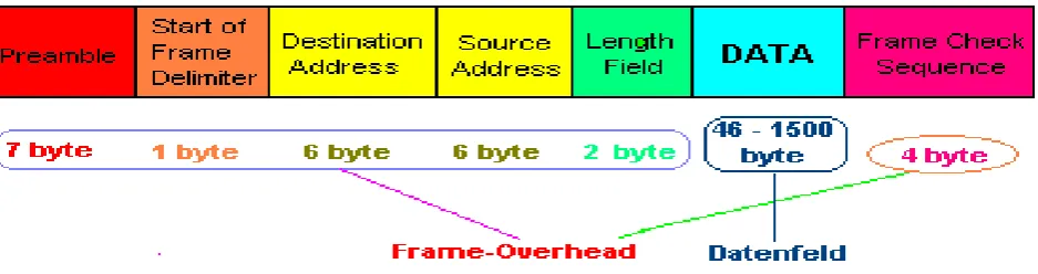
1.2.1Frame Structure
The structure of the frame is defined in IEEE 802.3 network standard.
This frame in a network contains of seven elements which are grouped into three key parts ie.
(SFD) which takes 1 byte, Destination Address (DA) which take 6 bytes , Source Address (SA) which occupy 6
bytes and Length which take 2 bytes [2].
Figure 1: Ethernet Frame Structure
1.2.2 Frame Aggregation in Wi-Fi
Frame aggregation in Wi-Fi is a standards feature that reduces delay by joining many frames which would have
been transferred individually into a single communication element.
Each frame transmitted by an 802.11n scheme that has a substantial amount of overhead and padding.
These overheads are constant and are incurred for every physical transmission, and they consume more
bandwidth than the payload of the frame.
In order to resolve this problem, a recent Wi-Fi 802.11n standard defines two kinds of frame aggregation
scheme, the Media access control (MAC) Service Data Unit aggregation and Media access control (MAC)
Protocol Data Unit aggregation (MPDU and MSDU) [3].
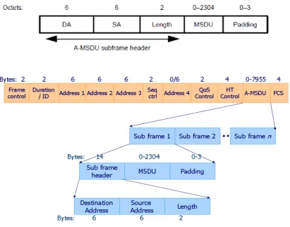
1.2.2.1 A-MSDU Aggregation
Aggregated-MAC Service Data Unit concatenated mutable MSDU frames being transmitted to the same
destination and must also originate from the same source device in Wi-Fi.
An MSDU frame is made up of header sub frame, payload, frame check sequence and padding sub frame.
The maximum aggregated size of the constructed A- MSDU can be computed by the formulae [3].
A-MSDUMax=5* Frame size(Bytes)
Figure 3: A-MSDU Subframe Structure
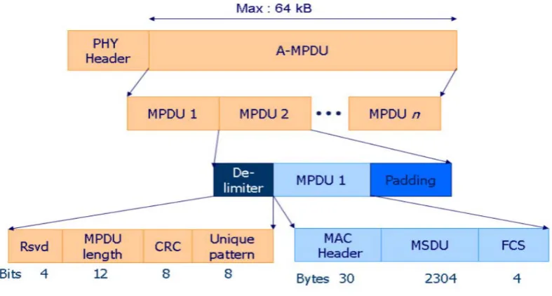
1.2.2.2 A-MPDU aggregation
Aggregated-MAC Service Data is constructed by combining multiple MPDU frames again these frame must
always be transmitted to the same destination in a Wi-Fi environment. MPDU is concatenated with a common
physical header for all MPDU data, delimiter and padding sub frames so as to construct a large A- MPDU.
These MPDU frames can be originating from different source but must always have the same destination. The
maximum aggregated size of the constructed A- MPDU can be computed by the formulae [3].
MPDUMax=2n – 1bytes
Where n=13+ The value is an integer that ranges from 0 to 3.
• 0: indicates that the maximum length of the A-MPDU is 8191 bytes. • 1: indicates that the maximum length of the A-MPDU is 16383 bytes. • 2: indicates that the maximum length of the A-MPDU is 32767 bytes. • 3: indicates that the maximum length of the A-MPDU is 65535 bytes.
The Maximum A-MPDU Length Exponent set to 3 in 802.11n which equals 65535 bytes which is
Figure 4: A -MPDU Frame Aggregation
1.3 Causes of Poor Quality of Service in Wi-Fi
The major course of poor quality of service in Wi-Fi is always related to allocation of network resources,
bandwidth management to different devices accessing. An inadequate network resource has to be shared by
many devices connected to access point. This sharing of resources has to be done in an effective way in order to
maintain quality of service e.g. delay, loss of packets and throughput [5].
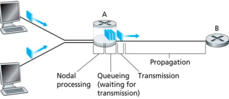
1.3.1 Delay
One way delay is the total time taken from the source to the destination, it can be from the access point to the
connected device or the vice versa. Packet delay can be obtained by summing up the delays on each wireless
links navigated by the packet. A delay links is made up of processing delay, queuing delay, transmission delay
and propagation delay. Where the processing the delay is a delay which take place from the time the packets are
received by the end device and the time they are release from transmission queue at the sending end. Queuing
delay on the other hand, is the delay which takes place between the times when the packets are assigned to the
transmission queue to the time when the packets begins transmitting to the end device. Throughout this time, the
packet delays while other packets in the same queue are transmitted to the destination. Transmission delay is a
delay that takes place between the time first packets is released to the time the last packets are conveyed. The
propagation delay is a delay that takes place from the time the last packets is transmitted at the link to the time
the last bit is received at the end device. Propagation delay is proportional to the distance between The sending
device and receiver device [5].
One way end to end delay is the total time in seconds, beginning when the packets are generated from the source
to the destination device on Wi-Fi. All the delays in a network are refer to as end to end delay and are obtained
by summing up the processing delay (PD1), queuing delay (QD), transmission delay (TD) and propagation delay
concern with it . Delays are normally in microseconds [6].
Figure 5: Types of Delay
Processing delay/Nodal delay (PD1) takes very short time as it is time taken to analyze the packet structure,
making a decision about the destination, identifying errors which may occur during transmission. This delay is
very insignificant at sending device in Wi-Fi and the receiving device does not always experience.
Queuing delay (QD) is the actual time the packet uses in a sending as it waits for other packets from the other
device to arrive and transmitted together.High speed acces points with few packets will experience low queuing
delay , while low speed devices with high data rate will experience high queuing delay . The average Queuing
delay(QD) is given by;
Queuing delay=𝒑𝒑𝒑𝒑𝒑𝒑𝒑𝒑𝒑𝒑𝒑𝒑 𝒍𝒍𝒑𝒑𝒍𝒍𝒍𝒍𝒑𝒑𝒍𝒍(𝑳𝑳) (𝒃𝒃𝒃𝒃𝒑𝒑𝒃𝒃)∗𝒑𝒑𝒂𝒂𝒑𝒑𝒂𝒂𝒑𝒑𝒍𝒍𝒑𝒑 𝒑𝒑𝒑𝒑𝒑𝒑𝒑𝒑𝒑𝒑𝒑𝒑𝒃𝒃 𝒑𝒑𝒂𝒂𝒂𝒂𝒃𝒃𝒂𝒂𝒑𝒑𝒍𝒍 𝒂𝒂𝒑𝒑𝒑𝒑𝒑𝒑(𝒑𝒑)
𝐋𝐋𝐋𝐋𝐋𝐋𝐋𝐋 𝐁𝐁𝐁𝐁𝐋𝐋𝐁𝐁𝐁𝐁𝐋𝐋𝐁𝐁𝐁𝐁(𝐑𝐑)
QD=L*a/R .(1)
Where packet length (L) is the size of the packets to be transmitted from the source to the destination in bits
while the average arrival rate (a) is the average rate of a new packets which arrive on the queue, expressed in
Common units are bits/second. In a queuing, at a given period of time, the packets usually arrive randomly. The
arrival of one packet is independent from arrival of other packets, and therefore they have different arrival rates.
Average arrival rate is therefore obtained by getting the mean of arrival rates of all packets to be transmitted.
Link Bandwidth(R) is the transmission capacity of wireless device i.e access point [6].
Serialization delay(SD) occurs due to the placing of packets into their appropriate queues.it is calculated as;
Serialization delay(SD) = 𝐅𝐅𝐅𝐅𝐁𝐁𝐅𝐅𝐅𝐅 𝐒𝐒𝐋𝐋𝐒𝐒𝐅𝐅(𝐅𝐅)
SD = F/S (2)
Transmission delay (TD) is the time taken to load the whole packet into the wireless media it can also be
epressed as the time it take to load all the packets in bits into a wireless media.. Transmission delay can be
computed by the following equation. [6].
Transmission Delay(TD) = 𝐒𝐒𝐋𝐋𝐒𝐒𝐅𝐅 𝐂𝐂𝐈𝐈 𝐁𝐁𝐁𝐁𝐅𝐅 𝐏𝐏𝐁𝐁𝐈𝐈𝐋𝐋𝐅𝐅𝐁𝐁 𝐋𝐋𝐋𝐋 𝐛𝐛𝐋𝐋𝐁𝐁𝐛𝐛(𝐋𝐋)
𝐓𝐓𝐅𝐅𝐁𝐁𝐋𝐋𝐛𝐛𝐅𝐅𝐋𝐋𝐛𝐛𝐛𝐛𝐋𝐋𝐂𝐂𝐋𝐋 𝐑𝐑𝐁𝐁𝐁𝐁𝐅𝐅(𝐑𝐑)
TD = L/R … (3)
Where packet length (L) is the maximum size or length of the packets in bits to be transmitted while
Transmission rate(R) is speed of the sending device or the access point used to transmit the whole packets to the
receiving wireless device.
Propagation delay(PD2) is the amount of time in milliseconds taken for a packets from the source to the
destination after it has been release to the wireless media .propagation delay indirectly proportional to the type
of access point i.e the stronger the access point the lower the propagation delay. Propagation delay is computed
as;
𝐏𝐏𝐅𝐅𝐂𝐂𝐒𝐒𝐁𝐁𝐏𝐏𝐁𝐁𝐁𝐁𝐋𝐋𝐂𝐂𝐋𝐋𝐁𝐁𝐅𝐅𝐂𝐂𝐁𝐁𝐝𝐝 (𝐏𝐏𝐏𝐏𝟐𝟐) =𝐏𝐏𝐋𝐋𝐛𝐛𝐁𝐁𝐁𝐁𝐋𝐋𝐈𝐈𝐅𝐅𝐏𝐏𝐅𝐅𝐂𝐂𝐒𝐒𝐁𝐁𝐏𝐏𝐁𝐁𝐁𝐁𝐋𝐋𝐂𝐂𝐋𝐋𝐛𝐛𝐅𝐅𝐁𝐁𝐁𝐁𝐅𝐅𝐅𝐅𝐋𝐋𝐁𝐁𝐁𝐁𝐅𝐅𝐛𝐛𝐒𝐒𝐅𝐅𝐅𝐅𝐁𝐁𝐁𝐁𝐋𝐋𝐅𝐅𝐅𝐅𝐂𝐂𝐅𝐅𝐛𝐛𝐛𝐛𝐂𝐂𝐈𝐈𝐁𝐁𝐁𝐁𝐅𝐅𝐁𝐁𝐈𝐈𝐈𝐈𝐅𝐅𝐛𝐛𝐛𝐛𝐒𝐒𝐋𝐋𝐏𝐏𝐋𝐋𝐁𝐁𝐂𝐂(𝐒𝐒𝐂𝐂𝐋𝐋𝐋𝐋𝐁𝐁𝐒𝐒) (𝐏𝐏)
PD2 = 𝐏𝐏/𝐒𝐒 ….…..(4)
Where D is the distance or range in meters between sending and receiving network device. S is the propagation
constant speed for network device. The propagation speed is constant normally it depends on the medium
connecting the two device. A constant propagation speed for wired media is S = propagation speed of the signal
(~3x10⁸ m/sec), while wireless media is S = propagation speed of the signal (~2x10⁸ m/sec) [6].
End-to-end delay(Dend-end) or one-way delay One way end to end delay is the total time in seconds, beginning
when the packets are generated from the source to the destination device on Wi-Fi. All the delays in a network
are refer to as end to end delay and are obtained by summing up the processing delay (PD1), queuing delay
(QD), transmission delay (TD) and propagation delay (PD2)
End-to-end delay(Dend-end)= Queuing delay (QD)+ Transmission delay (TD) + Propagation delay(PD2)
Dend-end= n[QD1+TD+ PD2]…… (5)
Where n is the number of nodes or access point.
As per the International Mobile Telecommunications and International Telecommunication Union(2015)
SO/IEC Standards any delay below 150ms are acceptable to all voice applications including convergent. On the
end to end delay above 150ms for voice and 400ms for video access categories is unacceptable as it is very
sensitive to applications [7].
Table 1: International Telecommunication Union(2015) SO/IEC Delay Standards
End-user performance expectations and quality of service requirements for International Mobile
Telecommunications-2015 (IMT-2015) access networks – Conversational/real-time services- International
Telecommunication Union(2015) SO/IEC Standards [7].
1.4 Related Work
Reference [8] Proposed a Single Queue Priority Scheduling Algorithm (SQPS) that is used by Wi-Fi IEEE
802.11n to improve the quality of experience and reduce the Packet Loss Rate of video transmission. In SQPS
framework, the data partition method assigns priorities after compressing the data while the layered coding
picks a base layer that is used to decode the entire video streaming. SQPS framework uses three metrics that is
deadline, priority and cost with weights to prioritize the video frames [8].
From the related work above on resource allocation techniques in Wi-Fi, Single-Queue Priority Scheduler
(SQPS) in optimizing video transmission in Wi-Fi IEEE 802.11n, it has addressed the challenges many mobile
video transmissions faces in standard wireless network. In SQPS framework, the video trace is prioritized by the
type of frame to be serviced. The importance of the various frame types is considered as the priority. SQPS
framework gives highest weight on deadline than priority yet online traffic have different priorities and QoS
requirements, it does not explain what happens to video traffic which does not utilized SQPS. Furthermore
SQPS makes use of the Motion Pictures Expert Group (MPEG) video frame in a compressed format leaving
behind other format modern formats such as AVI,WMV,MOV and MP4.The output simulation results shows
Medium Application Degree of
symmetry
Data rate (kbit/s)
Key performance parameters and target values One-way delay (ms) Delay variation (ms) Information loss
Audio Conversation at
narrow-band speech
Two-way 4-13 10
preferred 150 limit
1 3% PLR
Audio Conversation at voice wideband speech
Two-way 4-13 10-64
150 preferred 400 limit
1 3% PLR
Video Videophone Two-way 32-384 150
preferred 400 limit Lip-synch: 100
1% PLR
Data Telemetry
– two-way control
Two-way 28.8 250 Not applicable
Zero
Data Interactive games Two-way 1 250 Not
applicable
Zero
Data Telnet Two-way
(asymmetric)
1 250 Not
applicable
minimal drop in percentage packet loss ratio. A framework is needed which accommodated all data traffic [8].
The results of the control simulations for this framework shown that seamless video streaming in wireless
networks is subject to the packet loss. However, the video frame prioritization and scheduling by SQPS
algorithm can reduce the packet loss rate in a video streaming network. Hence, with the same resources, the
users can achieve more with a scheduling algorithm like the SQPS, since video traffic is considered highly delay
sensitive.
Reference [9] Proposed yet another related framework called Green Frame Aggregation Scheme (GFA). GFA
takes into consideration the frame error rate requirements of real-time applications and adjusts the sub-frame
size accordingly. Since most loss tolerant traffic requires low frame error rate, the error rate threshold, is also
low in GFA framework, Moreover, this threshold minimizes the overhead of varying the sub frame size when
the frame error rate is within the acceptable limits. GFA framework explains that high throughput can be
obtained by transmitting aggregates with the maximum sub-frame size under the best channel condition [9].
GFA is based on the A-MPDU frame aggregation technique and benefit from the idea of retransmitting the
corrupted sub-frames only. It aims to achieve high level of energy efficiency in all environment situations
especially in high interference environments. GFA dynamically chooses the appropriate A-MPDU sub-frame
size based on channel quality. GFA efficiently utilizes the energy budget that is associated with the maximum
A-MPDU sub-frame size. Green Frame Aggregation Scheme (GFA) is based on the A-MPDU frame
aggregation technique and benefit from the idea of retransmitting the corrupted sub-frames. GFA aims to reduce
the consumed amount of energy that needed for a reliable data transmission, the default implementation of the
MPDU aggregation provides fixed MPDUs size all the time. GFA dynamically chooses the appropriate
A-MPDU sub-frame size based on channel quality. GFA efficiently utilizes the energy budget that is associated
with the maximum A-MPDU sub-frame size. Green Frame Aggregation Scheme (GFA) above focuses on frame
aggregation which is supported by modern Wi-Fi 802.11n on real time application only but does not consider
reducing delay in Wi-Fi instead it focuses on reducing energy on Wi-Fi only. GFA also is limited non real time
applications. The performance analysis of this framework was carried out. GFA is implemented and evaluated
on a Linux based IEEE 802.11n wireless cards. The experimental evaluation over various channel conditions
shows that GFA significantly reduce the energy consumption compared to default Linux configuration in
extreme noisy environment. Moreover, the results shows that GFA out performs the (SFA) static frame
Aggregation sizing method in terms of network throughput and maintain the latency performance.
From the related work above on resource allocation techniques in Wi-Fi, Single-Queue Priority Scheduler Green
Frame Aggregation Scheme (GFA) is based on the A-MPDU frame aggregation technique and benefit from the
idea of retransmitting the corrupted sub-frames. GFA aims to reduce the consumed amount of energy that
needed for a reliable data transmission, the default implementation of the A-MPDU aggregation provides fixed
MPDUs size all the time. GFA dynamically chooses the appropriate A-MPDU sub-frame size based on channel
quality. GFA efficiently utilizes the energy budget that is associated with the maximum A-MPDU sub-frame
size. Green Frame Aggregation Scheme (GFA) above focuses on frame aggregation which is supported by
modern Wi-Fi 802.11n on real time application only but does not consider reducing delay in Wi-Fi instead it
2. Dynamic Aggregation Scheduler (DAS)
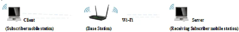
DAS Scheduler is implemented within both Base Station/Access point (AP) and Subscriber mobile device with
the aim of reducing delay, maintaining higher throughputs and reducing loss of packets. Different QoS
aggregation mechanism can be applied to each access category according to each requirement.
Table 2: Access Category and its QoS Required
Access Category
QoS Required
Explanation
Voice/Audio A-MSDU High Delay sensitive High Bandwidth demand and high data rate Video A-MPDU Delay sensitive High Bandwidth demand and high data rate
Best Effort A-MPDU Delay insensitive and Low bandwidth requirement hence have low impact on performance.
Background A-MPDU Delay insensitive and Low bandwidth requirement hence have low impact on performance.
Base station the incoming bandwidth is separated into inner and second Scheduler. The second Scheduler,
separate the delay sensitive voice packets from the incoming bandwidth which consist of all access category
applications i.e Voice, Video, Background and Best- Effort. A-MSDU frame aggregation technique is applied to
improve the throughput of Voice packets. A-MPDU frame aggregation technique is applied to video packets at
the First Scheduler while, Background and Best- Effort are transmitted into a receiving Subscriber mobile
station without aggregation because they are delay insensitive and require Low bandwidth hence have low
impact on performance.
Figure 6: Network Structured of Dynamic Aggegation Scheduler
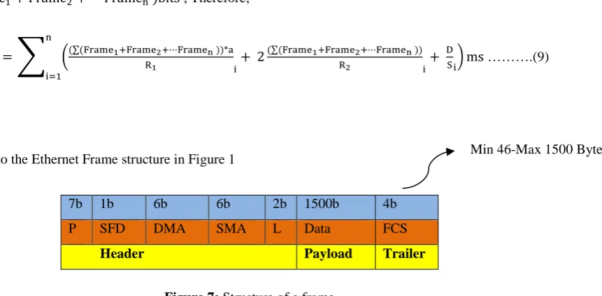
2.1Computing end to end delay
End to end or one way delay as per equation (5) is obtained by getting the summation of Queuing delay (QD),
Transmission delay (TD) and Propagation delay(PD).
Mathematically it can be shown as ;
Dend-end= n[QD+ 2TD+ PD]… (6)
Where QD is Queuing delay , TD is Transmission delay and PD is Propagation delay.
Therefore ;
A multiplier 2 is needed because transmission delay occurs at both sending and receiving end. From the above
formula “i” must always begin with 1 since wireless base station/ access point must always be not less than one.
n is the number of base station/ access point in which the frames passes through before the destination. The
overall end to end delay must be in millisecond.
Dend-end=� �L*aR 1i+ 2
L R2i+
D Si�ms n
i=1
….(8)
According to equation (1) QD=L*a
R1 Where QD is the Queuing delay, L is the length of the frame and R1 is
Link Bandwidth.
Equations (2) derive TD=L
R2 Where TD is the Transmission delay and L is the length of the frame in bits and
R2 is Transmission Rate and equation (4) derive PD=D
S Where PD is Propagation delay D is the distance
between the access point and wireless device. S is the wireless propagation speed. A multiplier 2 is needed
because transmission delay occurs at both sending and receiving end. The Length of the Frame (L) can be
obtained by adding all the frames in bits.
L = ∑(Frame1+ Frame2+⋯Framen )bits
From equation 3.3 above Dend-end=� �L*a
R1i+ 2
L R2i+
D Si�ms n
i=1
if L is replace by summation of frames
i.e ∑(Frame1+ Frame2+⋯Framen )bits , Therefore;
Dend-end=� �(∑(Frame1+FrameR12+⋯Framen ))*a i+ 2
(∑(Frame1+Frame2+⋯Framen ))
R2 i+
D Si�ms n
i=1
……….(9)
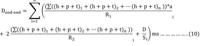
According to the Ethernet Frame structure in Figure 1
7b 1b 6b 6b 2b 1500b 4b
P SFD DMA SMA L Data FCS
Header Payload Trailer
Figure 7: Structure of a frame
where P is Preamble, SFD is Start of Frame delimiter, DMA is destination MAC address, SMA is
sourceMACaddress, L is the Length and FCS is the Frame check Sequence .
Frame size = Header size(h) +Payload size(p) +Trailer size(t)
Frame size =h+p+t
The header consist of 7 bytes of preamble, 1 byte of Start of Frame delimiter (SFD) , 6 byte of Destination
Address (DA), 6 byte Source Address (SA) and 2 byte to indicate the size or the length. Payload contain the
actual data ranging from 46 to 1500 bytes and the trailer which contain frame check sequence (FCS).
From Equation 3.4 above the each frame can be replaced by h+p+t where h is the header, p is the payload and t
is the trailer.
Dend-end=� �(∑((h + p + t)1+ (h + p + t)R 2+⋯(h + p + t)n ))*a
1 i
n
i=1
+ 2(∑((h + p + t)1+ (h + p + t)R 2+⋯(h + p + t)n ))
2 i+
D
Si�ms … … … . (10)
For Dynamic aggregation Scheduler , Frames are aggregated together to share Header and trailer. Therefore the
size of the frame L is obtained by summation of all payloads in each frame and the common header with
common trailer.
Therefore L=h+t+∑(p1+ p2+⋯pn)
Dend-end=� �(h + t +∑(p1R+ p2+⋯pn))*a
1 i+ 2
(h + t +∑(p1+ p2+⋯pn))
R2 i
n
i=1
+ DS
i�ms. … … … . . (11)
Computing Maximum Frame Aggregation Size for A-MSDU.
The structure of the frame takes a maximum of 1587 bytes(Maximum Padding space included) as shown in
figure 2.4, A-MSDU takes a maximum of Five Aggregated frames. According to equation 2.1, The maximum
Frame Aggregation Size for A-MSDU is given by the formular;
A-MSDUMax=5* Frame size(Bytes) where them Frame size =1587 bytes(With Padding bytes)
Therefore A-MSDUMax=5*1587 Bytes.
A-MSDUMax=7935 Bytes………..…(12)
Computing Maximum Frame Aggregation Size for A-MPDU.
MPDUMax=2n – 1bytes
Where n=13+ The value is an integer that ranges from 0 to 3. The maximum value is selected(3).
MPDUMax=26 – 1=65535bytes……….……(13)
Table 3: Access category , Delay Deadline Recommended and Maximum aggregated Size
Scheduler Access
Category
QoS
Required
Deadline recommended by IMT/TU and
SO/IEC 2015 Standards
Maximum
Size
First
Scheduler
Voice/Audio A-MSDU 150ms 7935bytes
Second
Scheduler
Video A-MPDU 400ms 64,535bytes
Third
Scheduler
Best Effort A-MPDU N/A N/A
Third
Scheduler
Background A-MPDU N/A N/A
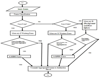
2.2 Flow chart of DAS
Frames of different access category are input into the system, a frame classification is done to establish which
access category i.e voice, video, best effort and background frames. The voice access category is separated from
other frames since it is very sensitive to delay than other access category. These frames are kept in memory z,
where they wait for the other frames of same access category to arrive in order to form A-MSDU with common
header. Time and size conditions are introduced. Timing is done in order to control the delay that is introduced
in this waiting process and maximum size of the aggregated frame is also controlled. If the time for this queue
expires or the aggregated frame reach the maximum size, then the content is sent to destination irrespective of
the time remaining or the aggregated size. The rest of the access category frames i.e. Video, Background and
Best-Efforts are forwarded to the next level. The next Scheduler Separate Video from the rest each of them, this
video frames is delay sensitive than best effort and background frames. Time and size conditions are introduced
again for video frames. Timing is done in order to control the delay that is introduced in this waiting process and
maximum size of the aggregated frame is also controlled. If the time for this queue expires or the aggregated
frame reach the maximum size, then the content is sent to destination irrespective of the time remaining or the
aggregated size. The remaining Background and Best-Effort are forwarded to buffer x. Finally Buffer x which
contain best effort and background is given the lowest priority as it is not sensitive to delay, it requires very low
bandwidth and have low impact on performance. Time and size conditions are introduced for best effort and
background. Timing is done in order to control the delay that is introduced in this waiting process and maximum
size of the aggregated frame is also controlled. If the time for this queue expires or the aggregated frame reaches
the maximum size, then it will be sent to destination without constructing A-MPDU.
2.3 Limitation and the Scope
In this study a simulation performance analysis was carried on both real and non-real time Access Categories
(AC) Applications. These Access Categories (AC) Application are voice, video, best effort, and background.
This framework was design to enhance the scheduling algorithm based on IEEE 802.11n Wi-Fi which supports
high speed streaming of convergence network and aggregation of packets. The Dynamic Aggregation Scheduler
framework was designed based on existing priority and two levels of packet aggregation schemes. The two level
of aggregation schemes are MAC Service Data Unit (MSDU) and MAC Protocol Data Unit (MPDU).
2.4 Simulation Results
A simulation was done using Riverbed modeler academic edition 17.5.Simulation results are presented to
demonstrate and evaluate the performance of allocation of bandwidth from base station access point to
Destination Wireless server in a control network environment.
The simulation was done in comparison without and with the proposed Dynamic Aggregation Scheduler and
the delay results as below.
In order to analyze sensitivity of varying packet size on delay when using Dynamic Aggregation Scheduler, The
simulation results are analyzed as per the varying number of packet size of 10,000KB, 30,000KB and
Table 4: The parameters of mobile wireless stations
Parameters Values of Client
Model Wlan_station_adv
Physical Characteristics HT PHY 5.0GHZ(802.11n)
Data Rate 65Mbps(base)-600Mbps(Max), ave 200Mbps
Frequency(GHz) 5.0GHZ
Rts Threshold(byte) None
Packet Size(bytes) Uniform(1000,2000) AP Beacon Intervals(secs) 0.02
Buffer Size(bits) 256000
Traffic Type Service /Traffic Category
Interactive Voice, Interactive Multimedia Video, Best Effort, Background
A-MSDU Capability Enable/ Disable A-MPDU Capability Enable/ Disable Maximum Transmitted 3839/7935
Maximum 8191
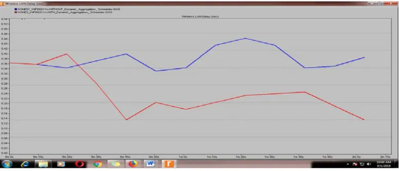
Average Delay in Seconds with and without Dynamic Aggregation Scheduler
Figure 9: Delays in Seconds with and without Dynamic Aggregation Scheduler for 10,000Kilobytes.
Figure 11: Delays in Seconds with and without Dynamic Aggregation Scheduler per 60,000Kilobytes.
The change in packet size in this Simulation control environment slightly alters the delays. There is a drop in
delay when using Dynamic Aggregation Scheduler compared to without Dynamic Aggregation Scheduler of
approximately 0.03 Seconds for 10, 000 kilobytes, approximately 0.10 Seconds for 30, 000 kilobytes and
approximately 0.15 Seconds for for 60, 000 kilobytes. Generally as the packet size increases, Dynamic
Aggregation Scheduler reduces the delay at increasing rate.
3. Conclusion
Although, this scheduling algorithm produced better QoS results there were still some losses in the network. As
also mention, the main improvements in Wi-Fi IEEE 802.11n are MIMO Technology, Channel Bonding and
MAC Layer enhancement. This research has only dwell on Aggregation on MAC Layer enhancement further
research can be carried out in other improvement on this Wi-Fi such as Channel Bonding and MIMO.
Furthermore, it will be good to see these simulations performed and compare with the simulation results of this
framework.
4. Recommendations
While significant QoS improvement have been made by using Dynamic Aggregation Scheduler to reduce
delay, further research can be carried out on Packet classification, Admission control. This research has only
dwell on scheduling and classification of packets as per access category, further research can be carried out in
other solutions such as admission control. Furthermore other QoS parameter also can be looked upon e.g loss of
packets and throughput.
As also mention, the main improvements in Wi-Fi IEEE 802.11n are MIMO Technology, Channel Bonding and
MAC Layer enhancement. This project has only dwell on Aggregation on MAC Layer enhancement further
research can be carried out in other improvement on this Wi-Fi such as Channel Bonding and MIMO.
framework.
Acknowledgements
I wish to express my profound gratitude to Dr. Agnes Mindila and Dr. Richard Rimiru for their support,
guidance and attention throughout the duration of this research work. I’ll like to specially thank everyone that
contributed to the success of this long but worthwhile journey, God bless you tremendously. Above all I thank
and praise the Almighty God, for providing me with sufficient Grace to enable me to accomplish my studies
successfully
References
[1] Michael M.(2013).Wireless Networking Absolute Beginners’ Guide. Pearson Education.
[2] Matheus, K. and Königseder, T. (2015). Automotive ethernet 1st Edition.United Kingdom: Cambridge
university press, pp.1-6.
[3] Jyoti K, Shoba K, Ninad S (2012)” Frame Aggregation Mechanism for High-throughput 802.11n
WLANS”.International Journal of Wireless & Mobile Networks (IJWMN) Vol. 4, No. 3, June 2012.
[4] Anwar Saif, Mohamed Othman, Shamala Subramaniam & Nor AsilaWati Abdul Hamid (2011) Frame
Aggregation in Wireless Networks: Techniques and Issues, IETE Technical Review, vol28 issue 4 ,
Jul-Aug 2011.
[5] Miguel B and Peter L (2011).QOS-Enabled Networks:Tools and Foundations 1st Edition. United
Kingdom: John Wiley& Sons Ltd.
[6] Kurose F.J, Keith R. (2013). Computer Networking. A Top-Down Approach. 6th ed. Pearson
Education.pp35-44.
[7] Dirk.W Weiler (2017).European Telecommunications Standards Institute 2017.PowerLine
Telecommunications(PLT);Quality of Service (QoS) requirements for in-house systems.
[8]Adejare,J.(2015).”Single Queue Priority Scheduler for Video Transmission in IEEE 802.11 Networks”.
University of Cape Town Presentation .
[9] Alaslani, M. (2015). “Green Frame Aggregation Scheme for IEEE 802.11n Networks”. King Abdullah
University of Science and Technology, Thuwal Kingdom of Saudi Arabia.
[10] Lu, Z. & Yang, H., 2012. Unlocking the Power of OPNET Modeler, Cambridge: Cambridge