EVALUATION TECHNIQUE FOR
FINDING OUT STRESS LEVEL OF
EXISTING BRICK MASONRY
STRUCTURE BY FLAT JACK METHOD
DIPESH MAJUMDAR*, MANOJ SAHIS+ ,ARPAN KARMAKAR±
Department of Construction Engineering, Jadavpur University, Kolkata, India, [email protected]
+Department of Construction Engineering, Jadavpur University, Kolkata, India, [email protected]
±Department of Construction Engineering, Jadavpur University, Kolkata, India
Abstract :In recent years, large research work has been made in this area, leading to inspection, non-destructive testing,monitoring and structural analysis of monuments. Nevertheless, understanding, analyzing and repairing masonry structures remains one of the most significant challenges to the civil engineering community.. This knowledge is necessary for the evaluation of the current condition of structures and can be also useful for stress control during repair operations. Study of literature reveals that laboratory studies were carried out to evaluate the existing stresses in masonry structures using flat jack method. This paper presents the details of the study carried out to evaluate the existing stress in the masonry specimens by Flat Jack method. Flat jack technique is used to evaluate existing stress level of brick masonry wall of an old building. The Flat Jack test result is compared with the theoretical value of stress and found to be in good agreement.
Keywords : Brick Masonry, Flat Jack
1. Introduction
Masonry is the world’s most common building material, existing as brick, concrete masonry, and stone construction. These types of masonry units have been used for thousands of years for most often as load-bearing walls in building structures, as masonry arch bridges, or as retaining walls. Unreinforced masonry has excellent resistance to compression loads but can suffer dramatic and brittle failure when subjected to lateral shear forces which may develop due to seismic loading or high winds. The analysis of masonry constructions poses important challenges because of the complexity of their geometry, the variability of the properties of traditional materials, the different building techniques, and the absence of knowledge on the existing damage from the actions which affect the constructions throughout their life. In addition, restrictions in the inspection and the removal of specimens in buildings of historical value, as well as the high costs involved in the inspections and diagnoses, often result in reduced information about the internal constructive system or the properties of the existing materials.
Engineers involved in structural analysis of existing masonry structures need information about the compressive stresses, the deformability properties and the loads applied .Flat Jack technique is a non – destructive testing way to evaluate the stress condition of in-situ masonry. Flat jack testing is direct and in-situ testing method that requires only the removal of a portion of mortar from the bed joints. It can be, therefore, considered non- destructive because the damage is temporary and is easily repaired after testing. Rossi (1987) developed the initial specifications for the optimum size of flat-jacks as well as positioning and techniques for measuring deformations and post-test analysis of data. (Rossi, 1987.)
2. Method of Flat Jack Testing:
2.1 Instrumentation and Testing
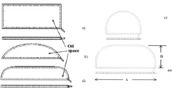
Fig. 1 : Different Shapes of flat jack
2.2 Hydraulic System
The pressure in the flat-jacks is provided by means of a pump (either manually or electrically operated), measured by means of a pressure gauge or a pressure transducer cell. The range of the cell should preferably be more than the working range of the flat-jack.
2.3 Gauges
The displacements can be measured by either mechanical gauges or LVDT’s. In any case the gauges should be able to measure up to 5 mm with accuracy of at least 0.01mm.
2.4 Cables and Data Acquisition
The cables used in all connections, from hydraulic jack to inlet ports of the jack, should be tight and without any sign of leakage. They should be able to sustain the pressure of the hydraulic fluid within the jack. The data acquisition system should have capability of temporarily storing the test data.
The flat jack method provides a relatively straightforward technique for the in-situ measurement of masonry compressive stress and deformability. No other non-destructive test method offers direct physical measurement of material and structural properties without reliance on empirical correlations. The degree of accuracy is generally compatible with the needs of analysis for typical retrofit projects, provided a calibration of the machine is done. [Gregorczyk & Lourenço , 2000]
3. Test Description
3.1 In-Situ Stress test (single flat-jack test)
This test is based on the principle of partial stress release and involves the local elimination of stresses, followed by controlled stress compensation.
Fig. 2 : Schematic diagram showing test procedure of Single flat jack test
3.2 Calibration of Flat Jack
Flat-jacks are designed to have an output pressure (one that is applied to masonry) that is linearly dependent on the internal hydraulic pressure. A flat jack has an inherent stiffness which resists expansion when the jack is pressurized. The pressure applied to the flat-jack is greater than the stress the flat-jack applies to the masonry. The flat jack must be calibrated to provide the conversion factor, (km ) to relate internal fluid pressure to stress applied. The coefficient that provides conversion (km) is determined during the calibration process.
km = P machine / P flat jack (1) The in-situ stress is evaluated using the following equation σm = ρ.km. ka
Where, σm = in-situ stress component to be determined, ρ = restoration pressure in flat jack at full compensation, km =flat jack calibration factor, ka = proportion of area of flat jack to area of slot.
The particular advantage of the stress relief and flat jack method is that knowledge of the elastic constants of the tested material (e.g. Young’s modulus and Poisson’s ratio) is not required. This is in contrast to other stress measuring methods.[Farvaze Ahmed et. al., 2013]
4. Description Building
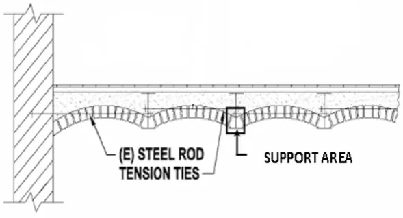
The flat jack test is carried out on an old heritage masonry building at Strand Road, Kolkata-700001. It is a brick masonry structure. It is a three storied office building. Height of each floor is around 6m. The external walls are about 900mm thick. Wall is constructed with brick masonry. Roof and intermediate slabs are constructed with steel joist and Jack Arch made with lime concrete. Jack arch portion is supported on steel joist. Steel joists are supported over brick masonry wall.
Owner of the building decided to rehabilitate the structure.
Before implementing any rehabilitation process flat jack testing is proposed to find out existing stress level of masonry structure.
5. Test Location
The test is carried out at 1st floor of the building. Test is done on the intermediate wall supporting steel joist portion. The test location is shown on Fig. No 4.
Fig.4: Plan showing test location
6. Load Calculation To Find Out Stress at Test Location
The testing operation is done on “X” marked location of the wall. Test position is on an intermediate wall (900 mm thick) which is supporting the floor slab.
6.1 Load calculation for 1st floor
Floor to floor height is 6m and the Flat Jack is fixed 1 m above from the floor. Influence area of that particular brick wall is (7.3 + 8)/2 m = 7.65m. (Fig. No 4) Average thickness of jack arch roof slab is found to be 350 mm. Unit weight of the lime concrete is assumed 20 KN/m³ (as per IS 875). Unit weight of the brick masonry is assumed 19.20 KN/m³
Unit weight of marble is assumed 27 KN/m³
(1) Self-weight of Slab = 7.65 x 0.35 x 20 = 53.55 KN /m
Floor to floor height is 6m and the Flat Jack is fixed 1 m above the floor. Height of testing point from floor = (6-1) m=5 m
(2) Self-weight of brick masonry wall= 5 x 0.9 x 19.20 = 86.4 KN/m
(3) Self -Weight for furniture and other super imposed dead load= 7.65 x 2 = 15.3 KN/m ( assumed SIDL on floor = 2 KN/m2 )
(4) Self-Weight of 40 mm thick marble floor =7.65 x 0.04 x 27 = 8.3 KN /m Size of the ISMB is ISMB 500x180
The unit weight of ISMB 500x180 is found 86.90 Kg/m = 0.86 KN/m
(5) Self-Weight of ISMB 500x180 = 0.86x7.65 KN/m = 6.6 KN/m ( no. of ISMB per meter length is 1) Total weight = 170.15 KN / m
6.2 Load calculation for Top floor –
(1) Self-weight of Slab = 7.65 x 0.35 x 20 = 53.55 KN / m
(2) Self-weight of brick masonry wall =6 x 0.9 x 19.20= 103.68 KN/m
(3) Self -Weight for furniture and other super imposed dead load = 7.65 x 1 = 7.65 KN/m (assumed SIDL on floor = 1 KN/ m2)
(4) Self-Weight of 40mm thick marble floor = 7.65 x 0.04 x 27 = 8.3 KN / m
(5) Self-Weight of ISMB 500x180 = 0.86x7.65 KN/m = 6.6 KN/m Total weight = 179.79 KN/m Total Calculated load on that wall = (170.15+179.79) = 349.93 KN/m
It’s observed that there is 20% opening per meter length of the wall. So 80 % of per meter length of the wall is bearing the total load.
So, Total pressure on that wall = 349.93/(0.8x0.9) KN/m2 = 486.0 KN/m2
7. Calibration of Flat Jack :
Flat-jacks are designed to have an output pressure (pressure on masonry) that is linearly dependent on the internal hydraulic pressure. The coefficient which relates the internal and external pressures of a flat-jack is called the calibration factor. The difference is due to the inherent stiffness of the flat-jack. The fluid pressure is always greater than the external pressure applied to masonry.
The coefficient that provides conversion (Km) is determined during calibration processes.
The flat jack (Size – 200x400 mm) used for the test is calibrated before the actual test on the masonry specimen. The calibration is conducted in 100kN capacity compression testing machine. ASTM C1196 is followed during the calibration test. A 50mm thick steel bearing plate is placed on the lower platen of the machine. The flat jack is placed on the lower bearing plate such that the edge of the flat jack with the inlet/outlet ports is coincident with the edge of the bearing plate. The steel spacers are placed around the other edges of the flat jack. Another 50mm thick bearing plate is placed on the top of the shims and flat jack and it is aligned in such a way that the upper and lower plate are in the same line. The moveable platen is raised such that the non-moveable platen is in contact with the top bearing plate. To maintain constant distance between platens during the calibration, a dial gauge is fixed over the 50mm steel plates. Before start of the calibration, three cycles of Pressurization and depressurization with the maximum pressure in the flat jack not exceeding 50 bars is carried out ( max capacity of the flat jack is 50 bars). Pressure in the flat jack is increased to 2bar increments up to 12 bars while holding the distance between platens constant. At each increment, flat jack hydraulic pressure and force measured by the machine is recorded. The load applied by the flat jack is calculated as internal pressure times gross flat jack area. During calculation of pressure measured in compressive testing machine effective contact area is considered 20.0cm x 20.0cm.
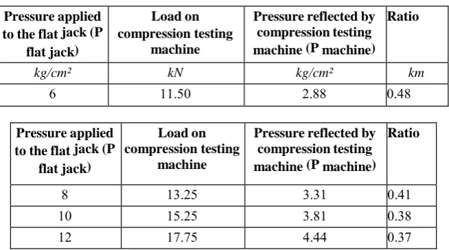
(Load corresponding of 11.50kN = (11.50 x 100) / (20.0x20.0) =2.88kg/cm² km = P machine / P flat jack (1)
Table 1: Flat jack & Compression testing machine readings during calibration process
Pressure applied to the flat jack (P
flat jack)
Load on compression testing
machine
Pressure reflected by compression testing machine (P machine)
Ratio
kg/cm² kN kg/cm² km
6 11.50 2.88 0.48
Pressure applied to the flat jack (P
flat jack)
Load on compression testing
machine
Pressure reflected by compression testing machine (P machine)
Ratio
8 13.25 3.31 0.41
10 15.25 3.81 0.38
12 17.75 4.44 0.37
From the calibration test the flat jack calibration factor (km) evaluated is 0.41 (from Table: 1).
8. Surface Preparation:
Proper surface preparation of the brick surface is an important factor in ensuring good performance of flat jack test method. In this process at first a small portion of mortar is removed & it is identified that the mortar is made of lime Surkhi. Brick of masonry structure is clay burnt in nature. The brick size is measured at site and found to be 65 x 100 x 210 mm. Bricks joints & arrangements type is observed and noted. Then one particular brick joint is marked and decision is made for testing. Necessary arrangement is started to insert the jack plates. Mortar is removed from the brick surface with help of hammer & chisel very carefully avoiding distortion of any brick so that the bricks and brick joints are clearly visible. Then the brick surface is dressed by sand paper and then the surface is cleaned by clean water.
9. Fixing of LVDT:
respect to increase of pressure is noted. This process is continued until the initial reading of LVDT is reached
12. Result & Discussion:
Flat Jack method is used to determine the in situ stress and compressive strength of masonry structures. A flat jack is a hydraulic load cell manufactured to be very thin, for insertion into a typical mortar joint into which a slot has been formed. When pressurized, the flat jack exerts stress on the surrounding masonry and by measuring surface deformations information on the existing state of stress as well as the stiffness and strength of masonry can be obtained. This is a very convenient testing system.
In the present work, flat jack system is used to evaluate existing stress level of masonry wall so that a comparison can be made between calculated stress and actual stress.
A very old building at Stand road, Kolkata- 01, is chosen for the testing. It’s a very old brick masonry structure with clay burnt bricks and lime-mortar.
The test is described in further detail below.
12.1 First step: Fixing of LVDT on existing wall before fixing flat jack on wall
As a first step two LVDTs are fixed at convenient position. Two LVDTs are fixed on the wall in such a way that Flat Jack may be placed at central position of LVDT. Reading of LVDT is noted before taking out mortar between two brick layers.
Readings of two LVDTs:
The initial reading of LVDT 1 = 13.20 mm The initial reading of LVDT 2 = 7.80 mm
12.2 Second step: Fixing of flat jack into slot cut in the brick wall.
A 200mm X 400 mm rectangular flat jack is used for testing. A slot is made in such a way that the plate could be inserted. Then the plate is inserted into that slot and void between plate and brick surface is filled by cementitious mortar with very low W/C ratio. Then two LVDTs are fixed and readings of LVDT are noted. As mortar between two bricks is taken out manually, load is released on that particular zone. Releasing of load affect the LVDT readings, as distance between two points is decreased due to load release
Reading of two LVDTsReading of LVDT 1 = 12.82 mm Reading of LVDT 2 = 7.69 mm 12.3 Third step: Pressurization of flat jack
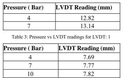
A hydraulic jack is installed with the valve (one way valve) of the flat jack plate. Then the flat jack is pressurized gradually. With the increasing of pressure the LVDT readings is also increased. The process is continued until the LVDT’s reading reached the initial reading (before cutting the slot). The Pressure vs LVDT readings are presented in Table 2 and 3.
Table 2: Pressure vs LVDT readings for LVDT: 1
Pressure ( Bar) LVDT Reading (mm)
4 12.82
7 13.14
Table 3: Pressure vs LVDT readings for LVDT: 1
Pressure ( Bar) LVDT Reading (mm)
4 7.69 7 7.77 10 7.82
pressure of this cutting zone of the wall.
So, the experimental stress from flat Jack = 10 bars
The pressure applied to flat jack is not totally transferred to the brick masonry due to the inherent stiffness of the flat-jack, which resists expansions when the jack is pressurized. Another factor that contributes to this effect is the difference between the area of jack and the area of slot. Both these factors are taken in account while interpreting test results. This is taken care of by the calibration of the flat jack carried out in the laboratory and described in Chapter 3.
Stress develop in brick masonry = (the stress from flat jack) x Km (flat jack calibration factor) = 10 x 0.41 = 4.1bars = 4.18 Kg/c.m2
The theoretical calculated stress in the brick masonry is 4.86 Kg/cm2 (Refer Item No. 6.2)
The measured stress in brick masonry is found to be in good agreement with the theoretical calculated stress.
Plate 1 : Photograph showing LVDT and Flat Jack fixed in wall after cutting the slot.
13. Conclusion
The flat jack method provides a relatively straightforward technique for the in-situ measurement of compressive stress and deformability of brick masonry. No other non-destructive test method offers direct physical measurement of material and structural properties without reliance on empirical correlations. The degree of accuracy is generally compatible with the needs of analysis for typical retrofit projects.
The test requires some skill and care, particularly in dealing with the problems of voids or frogs in the mortar joints. Not only will significant inaccuracies be introduced if voids are not properly spanned, but the flat jack may inadvertently became a permanent part of the structure. Also, care must be taken not to damage the structure during cutting of slots.
Flat jack tests may easily be integrated into the structural evaluation process, and provide data that is complimentary to other nondestructive tests. Information concerning the states of stress at various points throughout the structure can be helpful in the interpretation of data from the other non destructive test.
[6] Dario Almesberger, Antonio Rizzo and Sergio Meriani, “Non Destructive Investigations for the Safeguard of the Tower of the Orologio, in San Marco Square in Venice” Proceedings of 15th World Conference on NonDestructive Testing 15-21 October 2000, Rome
[7] A.P. Russell, H. Mahmood, J.M. Ingham, “Pseudo-Static In-Plane Testing of Typical New Zealand Unreinforced Masonry Walls” 8th
Pacific Conference on Earthquake Engineering, 5-7 December 2007, Singapore
[8] Michael Schuller, “Flatjack Methods for Diagnosis of Modern Masonry”, Proceedings of the RILEM International Workshop on Site
Control and Nondestructive Evaluation of Masonry – Structures and Materials, Mantova, Italy, 12- 14th November 2001
[9] Pawel Gregorczyk and Paulo B. Lourenço, “A Review on Flat-Jack Testing”, Engineering Civil, UM, No.9, 2000, pp. 39-50.
[10] John C Scrivener, “Old Masonry Buildings: Earthquake Performance and Materials Testing”, Internal Report No. 624, Institute for
Research in Construction, National Research Council, Canada, Mar. 1992
[11] IS: 13311 Part 2-1992
[12] IS13311 –Part 1:1992
[13] Impact-Echo Instruments, LLC Ithaca, New York
[14] Paweł Gregorczyk 1, Paulo B. Lourenço2 Universidade do Minho, Departamento de Engenharia Civil Azurém, P – 4800-058
Guimarães, Portugal
[15] Evaluation of In-situ stress in masonry structure by flat jack techniqueS. Parivallal1, K. Kesavan 1, K. Ravisankar 2, B Arun Sundram
3 and A K Farvaze Ahmed 3
[16] A. Carpinteri, S. Invernizzi & G. Lacidogna Dipartimento di Ingegneria Strutturale e Geotecnica, Politecnico di Torino, Torino, Italy.
Studies on Calibration Factor of Flat-Jack for Measuring In-Situ Stress on Concrete Members A.K.Farvaze Ahmed, K.Ravisankar, B.Arun Sundaram, S.Parivallal and K.Kesavan
[17] Non destructive testing applied to historic buildings: The case of some Sicilian Churches. L. Binda and A. Saisi Politecnico of Milan,
DIS-Dept. of Structural Engineering, Milan, Italy L. Binda and A. Saisi Politecnico of Milan, DIS-Dept. of Structural Engineering, Milan, Italy.