OPTIMIZED DESIGN OF BIO-SENSOR
USING CONDUCTING POLYMERS AND
NANOCOMPOSITES
Smt Usha.A
Department of E & E Engg, IEEE Member BMSCE, Bull Temple Road, Bangalore-560019,Karnataka,India
B.Ramachandra
Department of E&E Engg,PESCE, Mandya,Karnataka,India
M.S. Dharmaprakash
Department of Chemistry, BMSCE, Bull Temple Road,
Bangalore-560019,Karnataka,India
Abstract:
This Research work is focused on the design, development and technological evolution of emerging fields of Nanotechnology and Conducting Polymer Electronics, Bio-Tech based Embedded Sensors and Smart Systems employing System-0n- Chip (SOC) Core, as applied to Health Monitoring of Human and Complex Systems in Engineering and Medicine. With the Invention of Thin-Film Technology, it is now possible to fabricate Novel Conducting-Polymer based sensors and devices with built-in-flexible electronics resulting in high throughput devices and systems that are flexible, lighter, bio-compatible and economical also. The flexible and Embedded Electronics is a key enabler for a number of platform methodologies such as Designed Thin-Films, Smart Electronics and Sensor Devices. The integration of the Bio-Sensor with embedded electronics data conditioning and processing SOC and Wireless –Communication System may provide vast opportunities for Biological – Sensor Applications, especially for physiological monitoring of Leukocyte-Counts in blood sample or analyte for Leukemia Patients in the Society.
Keywords: Nanoparticles; Conducting polymers; Signal conditioning and processing Electronics.
1. Introduction
In earlier days, the traditional method of counting Leukocytes is by stain method. But in recent days, Auto-analyzers are used for the same. For bio-sensing, labeling is a basic requirement for detecting and analyzing biomolecules and bio-reactions.
sample is thermally activated and depends exponentially on temperature, much as in semiconductors but unlike metals. Stability and processing characteristics have been the main barriers to the commercialization of these materials. Stability pertains primarily to reactivity toward oxygen or moisture. Doped Polyacetylene, one of the earliest conducting polymers, has a conductivity of 1, 50, 00,000 s/m at room temperature. But as it is also very reactive towards oxygen and moisture, it rapidly suffers irreversible loss of conductivity in the atmosphere. Several other polymers exhibit much greater stability toward ambient conditions, including Polypyrrole, Polyaniline and Polythiophene. While not as conductive as polyacetylene, they do well enough for several other applications.
Conducting polymers are prepared in two steps, which can be simultaneous or sequential. First, the polymer is formed from its base material by a conventional chemical polymerization process. The molecular structure of such polymers typically has considerable delocalization of electrons along the polymer chains. This structure is also conductive to formation of energy bands, from and to which charge carriers can be easily removed or added. The second step in the preparation of conducting polymers is the creation of charge carriers by reaction with a chemical oxidizing or reducing agent. Among the common dopants are halogens (like iodine or bromine), organic oxidizing agents and alkali metals like (sodium or potassium).
Doping can also be accomplished by adding or removing electrons electrochemically. In this case, charge is balanced by incorporating ions from the electrolyte. The choice of dopant and doping method determines the polymer’s magnetic, electrical and optical properties and in some cases also influences its processing characteristics. For this specific application, polypyrrole with a conductivity (2.0X10⁵) s/m and polyacetylene (1.5X10⁷ ) appears to be the right choice because of its conductivity and performance characteristics at room temperature and pressure. A glass substrate, (SiO2) forms the base of the sensor, above which (ITO) Indium
Coated Tin Oxide layer provides the proper contact between the base and the sensor.Polypyrrole and polyacetylene solution in different proportions along with doping nano materials as either gold or silver is the optimized composition for the bio sensor. Silver or gold nano-materials can be added as dopant in different proportions (10ppb or 100ppb or 1000 ppb). Specific enzyme or oxidize or antibody (peroxidase) will be coated to stabilize and ease the immobilization of enzyme and to enhance the concentration of enzyme redox centers. Using electrochemical technique, thin film of the sensor designed and will be prepared which constitutes mainly the novel conducting polymers such as polypyrrole and polyacetylene multiple-layer composite film with nano materials i.e., either gold or silver or carbon nano tubes. With maximum surface area, i.e., more number of active sites which can assist the enzyme or antibody to enhance the immobilization of enzyme while interacting with the specific analyte or the sample. The analyte employed here is blood sample, in which the WBC or Leukocyte counts are initially traced and identified by observing and analyzing various performance characteristics of the bio sensor at room temperature by using the Two-probe or Four-probe technique. Essentially this scheme is more advanced than the traditional or earlier dye or stain method of WBC counting in blood sample. Further this technique appears to be more efficient with less human intervention and reduced time consumption by using only a small amount (Micro-litre or 0.5 ml) of the sample or analyte.
In future, the same technique can also be employed for the analysis of differential Leukocyte counts (Neurophiles, Lymphocytes and Eosinophils) in blood sample and hence the Leukemia patients can be treated in advance at most appropriate time which in turn will be a boon to the public or society.
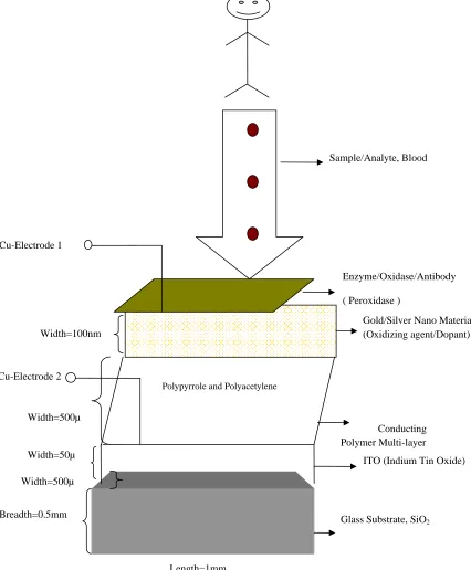
2. Sensor Film Design
Figure 1: Sensor Film Design
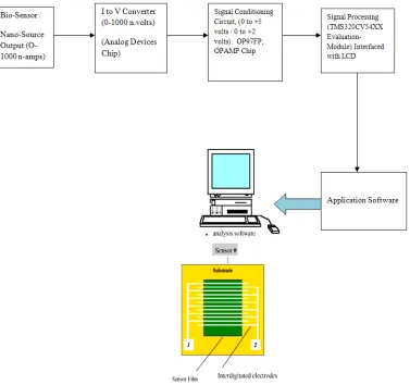
3. Signal Conditioning Electronics
Bio-Sensors that use thin-film technology typically require high-gain signal conditioning and processing circuitry. Sensors employed for biological applications that are designed using conducting polymers and nanocomposites require signal conversion and amplification of several units of volts per nano-amperes current range. To start with, initially Nano-Current source is designed and Constructed using discrete, passive components which can produce 0 – 1000 nano-amps current signal. This signal is approximated to be proportional to the sensor output which corresponds to the leukocyte count variations in blood sample. Then the nano-current signal is conditioned using Analog-Devices chip (ADOP97FP OPAMP). This IC converts efficiently nano-signal (0-1000 nano amps) into milli-volts range (0-1000 milli volts) without noise and
ITO (Indium Tin Oxide) Gold/Silver Nano Material (Oxidizing agent/Dopant) Enzyme/Oxidase/Antibody
( Peroxidase )
Glass Substrate, SiO2
Polypyrrole and Polyacetylene
Conducting Polymer Multi-layer Sample/Analyte, Blood
Cu-Electrode 1
Width=100nm
Width=500µ
Breadth=0.5mm
Length=1mm Width=500µ
interferences or losses. Further the signal was modulated to produce (0 to +5 volts) dc voltage by modifying the OP97FP opamp circuit.
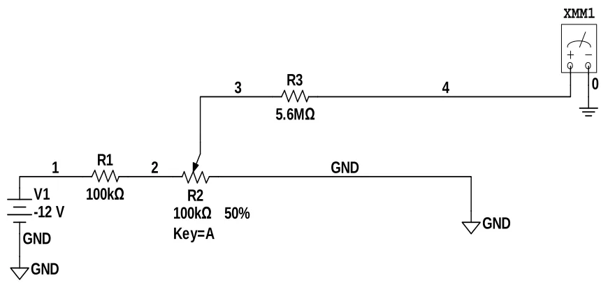
Bio-Sensor output is simulated by designing nano-signal current source. A simple current source is constructed by -12 V output from an ideal voltage source and a voltage divider to adjust the voltage, V, across a 5 MΩ resistor. The voltage divider consists of a 100 KΩ resistor in series with a 100 KΩ potentiometer. The 5.6 MΩ resistor is connected to the moveable contact (wiper) of the potentiometer. The obtained output varies between 0 to 1000 nanoamperes as shown in the Figure 2.
R1
100k
Ω
R3
5.6M
Ω
GND
V1
-12 V
GND
GND
GND
3
XMM1
R2
100k
Ω
Key=A
50%
0
4
1
2
Figure 2: Nano-Source Circuit (Designed Bio-Sensor Output Simulated in the Laboratory)
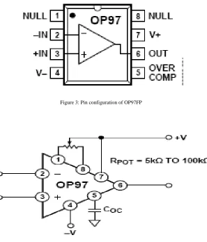
Figure 3: Pin configuration of OP97FP
Figure 4: Input Offset Voltage Nulling and Overcompensation Circuit
U1
OP97FP
3
2
4 7
6 8 1
R1
10kΩ
R2
10kΩ
R3
4.7MΩ
C1
4.7uF
V1 12 V V3 12 V 2
4
5 6 0
R4
470Ω
3
I1 200nA
1
XMM1
0
XCP1
9 0
0
7
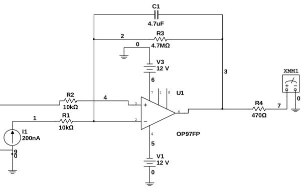
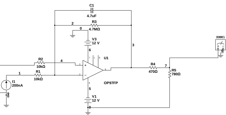
Figure 5 : Circuit for current to voltage conversion using OP97FP OPAMP
The Nano Current Signal generated (which is approximated or assumed as the Designed Bio-Sensor Output) applied to the inverting terminal of the opamp. In this case the circuit is designed and constructed such that an output DC Voltage of 5V for 1000nA is achieved. The value of the feedback resistor, Rf (gain) can be calculated from the below equation.
3.1. Design
OUT = - (G) × IN
= - (Rf ⁄ Ri) ×IN
= -Rf × IN , if Ri=1,
Rf = - (OUT ⁄ IN) = - (5V ⁄ 1µA)
= 5 M Ώ
As the Operational Amplifier, OP97FP is capable of producing Current to Voltage Conversion with high gain, it is selected so that an input current of 1 nA produces an output voltage of 5 mV.
U1 OP97FP 3 2 4 7 6 8 1 R1 10kΩ R2 10kΩ R3 4.7MΩ C1 4.7uF V1 12 V V3 12 V 2 4 5 6 0 R4 470Ω 3 I1 200nA 1 XMM1 0 R5 780Ω XCP1 9 0 0 7
Figure 6: Signal conditioned circuit using OP97FP
U1 OP97FP 3 2 4 7 6 8 1 R1 10kΩ R2 10kΩ R3 4.7MΩ C1 4.7uF V1 12 V V3 12 V R4 470Ω XMM1 R5 780Ω 0 2 0 5 4 R6 100kΩ R7 5.6MΩ GND V2 -12 V R8 100kΩ Key=A 50% 10 GND 3 1 6 0 11 9 7 0
Figure 7: Complete Circuit from Nano-Source to Signal-Conditioned Output
The results obtained from the previous Circuit is now considered for 0 to 500nA and the output is modified or restricted to DC Voltage i.e. 0 to +2V for further processing with DSP and the obtained values are listed in the Results Section.
4. Embedded SOC Design
different proportions (for example: PPY+ polyacetylene; 50%+50%, 40%+60%, 70%+30%, 60%+40%) to which gold or silver nano composites will be added as 10ppb or 100ppb 0r 1000ppb to the prepared multi-layer to enhance the existing surface area of the film to accommodate more active sites during reaction and in turn sensing of the device with the required analyte or sample.
The effect of temperature and atmosphere may affect the sensing on film properties. Hence usually the fabrication of the film will be carried out at clean room or ultra clean room, using sophisticated equipments to reduce the error to the maximum extent during the characterization of the synthesized film and application of the sensor in Real Time Bio-Medical Systems. Our approach focuses on the Optimum design of the Sensor, Signal Conditioning Circuitry and Processing of Bio-Signals for Real Time Applications.
The uniformity in the deposition process and surface morphology of the films will be observed by AFM studies. At room temperature and pressure, Two-probe or Four-Probe conductivity measurements can be performed. The proposed biosensor synthesized consists of interdigitated electrodes made from copper or platinum on quartz plate. We can find the result of the conductivity change of the sensor films at room temperature. The film synthesized will be compatible with signal conditioning electronics circuitry, with the change in resistance or conductance or impedance can be recorded as WBC count varies in the sample.
Designed and Constructed advanced signal conditioning circuitry mainly consists of an Application Specific Integrated Circuit (ASIC designed using OP97FP Analog Devices Chip) with associated components that process the raw output obtained from the bio-sensor (which is simulated using Nano-Source circuit). The ASIC works with low voltage and low current, with wide operating temperature range. The proposed bio-sensor which is basically made of conducting polymers and nano-composites will be very much sensitive to temperature and pressure. The ASIC selected enables output adjustment, signal conversion, conditioning, amplification and processing the acquired data of the sensor. ASIC operates at +5V input and provides an output of 0.1 to 5V for an input current signal ranging from 10 to 1000 nano-amperes, released by the bio-sensor as the leukocyte count varies in the blood sample. Presently efforts are initiated to incorporate high resolution ADC with the signal processing electronics that gives a serial digital output display using the LCD and TMS320C54XX DSP Processor Evaluation Module.
5. Results and Discussion
In this Research work, effectively Bio-Sensor design is optimized for biological real time applications using Conducting Polymers (polypyrrole + polyacetylene) and gold or silver Nanocomposites. Nano-Source is designed and constructed efficiently by employing discrete Electrical components, the output of which corresponds to the designed Bio-Sensor signal output i.e. in the order of 0-1000 nano-amps. Further nano-amps current signal is converted into milli-volts by using Analog Devices Chip (op97fp, opamp). After Signal Conditioning, we practically achieved 0 to +5 volts DC Voltage. Then the circuit modified to obtain 0 to +2 DC Volts for 0 to 500 nano-amps current signal. Further the conditioned signal is processed (filtered) to eliminate noise and interferences present in the signal output using DSP 5416 Target Board and processed signal data is displayed on an LCD which is interfaced with the DSP Evaluation Module.
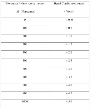
The results obtained practically in the Laboratory for the Signal Conditioned Circuitry employing OP97FP OPAMP and discrete components given in the Figure 5 are as shown in the below Table 1.
Table 1: Obtained Practical Results
Bio-sensor / Nano source output
∆I (Nanoamps)
Signal Conditioned output
( Volts)
0 + 0. 0
100 + 0.5
200 + 1.0
300 + 1.5
400 + 2.0
500 + 2.5
600 + 3.0
700 + 3.5
800 + 4.0
900 + 4.5
1000 + 5.0
The results obtained practically in the Laboratory for the Signal Conditioned and Modified Circuitry employing OP97FP OPAMP and accessory components given in the Figure 6 are as shown in the below Table 2.
Table 2: Modified Practical Results
Bio-sensor / Nano source output
∆I (Nanoamps)
Signal Conditioned output
( Volts)
0 + 0.0
100 + 0.4
200 + 0.8
300 + 1.2
400 + 1.6
500 + 2.0
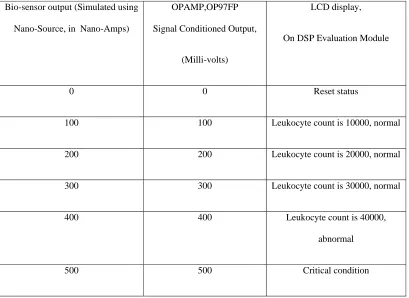
The results obtained practically in the Laboratory for the Signal Conditioned and Processed Circuitry employing OP97FP OPAMP, accessory components and DSP Target Board interfaced with the LCD given in the Figure 8 are as shown in the below table 3.
Table 3: Data Displayed on LCD
Bio-sensor output (Simulated using
Nano-Source, in Nano-Amps)
OPAMP,OP97FP
Signal Conditioned Output,
(Milli-volts)
LCD display,
On DSP Evaluation Module
0 0 Reset status
100 100 Leukocyte count is 10000, normal
200 200 Leukocyte count is 20000, normal
300 300 Leukocyte count is 30000, normal
400 400 Leukocyte count is 40000,
abnormal
In future the real time resistance changes of the film will be monitored with computer interfaced electro-meter after applying analyte or sample on the film. The future work focuses on the synthesis and characterization of the sensor ( at IISC Nano-Fab Lab )which in turn represents change in the resistivity or conductivity of the film at room temperature and pressure. We can also use both the four–probe copper electrodes deposited on (AL) alumina substrate for online and real time bio-medical applications.
The change in resistance (∆R) or conductance or impedance values obtained for three different types of (ppy-p.acetylene+nano-composites) sensor films will be recorded which can be analyzed, conditioned and processed also using LABVIEW Application Software.
The total change of the resistance (∆R) or conductance will be calculated from the subtraction of resistance at normal WBC count in the blood sample (standard or reference value) with each change of the resistance or conductance after introduction of affected blood sample or analyte. Further it can be marked or read that the total change in the resistance or current or voltage value versus Leukocyte counts concentration in the blood sample. Here, in future we want to study, analyze, convert, condition and process the effect on synthesized and characterized sensor thin-film membrane after the introduction of Micro-liter or 0.5 ml of sample or required analyte. Then change in the resistance or conductance or current will be observed on the (conducting polymer + nano-composites) film as soon as the sample is introduced in the measuring unit or coated on the surface of the sensor.
6. Conclusion
In this work, an attempt has been made to optimize design of the Bio-Sensor using Conducting Polymer-Nano-Composites hybrid structure on glass, ITO coated glass plate with interdigitated Copper electrodes. This proposed technique for measurement of leukocyte counts in blood sample is label-free, quite fast, rapid, cost effective, low power, less human intervention which can be easily installed. In order to be useful as a sensor, the device and the technique should be able to detect the Leukocyte counts at relevant very low concentrations (micro-liter or 0.5 milli-liters).
Design and Construction of Nano-Source Circuit has been effectively implemented in this research work which produces Nano-Current signal output that corresponds to Designed Bio-Sensor Output in the range of (0-1000) Nano-Amps. Further ASIC is designed which incorporates Signal Acquisition, Conversion, Conditioning, Analysis and Processing of the required data or message. Finally desired information is displayed on the LCD interfaced with the DSP-Evaluation module after sensing leukocyte counts in the blood sample or analyte.
We can use in future, UV-Vis Spectroscopy, SEM (Scanning Electron Microscopy), AFM (Atomic Force Microscopy), conductivity, IV and CV measurements to quantify the different characteristics of the nano-composite polymer films synthesized to ensure reproductability, stability, reliability and adaptability for bio-medical real time applications which in turn is useful to the people or public for the welfare of the modern society. Enzyme or antibody based bio-sensors in future are known to be widely used for detection or identification of various virus or bacteria present in the blood sample of human beings and also people can be treated at the earliest, in turn damage to human beings can be prevented to the greater extent. This proposed new innovative concept details the advanced Signal Conditioning and Processing Electronics (SOC) involved in the design of bio-sensor (with required electronics circuitry) for leukocyte counts in blood sample for real time applications using conducting polymers, nano-composites and DSP Processor which can implement the application software for various bio-signals within the set deadlines and in turn it will be a great contribution to the people or society.
Acknowledgements
We acknowledge Chetan Ghatage, M.Tech Student for the support in Design and Implementation of Nano-Source and Nano-Bio-Signal Conditioning and Processing Circuit. We also thank Dr Ravishankar Deekshit for extending the Electrical and Electronics Laboratory Facility while carrying out Research work. Further, we would like to extend our heartfelt thanks to Dr Mahesh for his technical guidelines.
References
[1] Ben Hur V. Berges and Luiz Eugenio M de Barros Jr.(1999) "Design of optical Bio-sensor using polymeric waveguide” SBMO or IEEE MTT – SIMOC 99 Proceedings.
[2] Holmes D, Taosun Morgan .H, Holloway J, Cakebread J, Davies .D. (2007) “Label Free differential Leukocyte counts using a Microfabric single cell Impedance Spectrometer”, Sensors, IEEE.
[3] M.Lee and P.M. Fanchet, The Institute of Optics, (2006) "Label – Free optical Bio-Sensor using silicon two dimensional photonic crystal”, IEEE.
[5] Mohd. Zahid Ansari & Chongducho. (2008) "Design and analysis of a high sensitive Microcantilever Bio-sensor for biomedical applications",IEEE.
[6] M.Ohkawa, M.Izutsu & T. Sueta, (1989) "Integrated optic accelerometer employing a cantilever on a silicon substrate" Jap J. Appl. Phys 28 (2) 287-288.
[7] Yunan Cheng, Gangwu, Gustaaf Borghs, MangWang, Hong-Zheng Chen (2008) “Electro Chemical Polyaniline/ Polypyrrole Composite Film with Novel Nano-structure and high Bio-Sensitivity”. Dept. of Polymer Science and Engineering, State Key Lab of Silicon Materials, China.
[8] Michel Bozlan, Fabien Miomande and Jinbo Bai (2008) “Electrochemical Synthesis and Characterization of Carbon Nano tube or Modified Polypyrrole Hybrids Using a Cavity Micro Electrode”, France, Science Direct Journal, September.
[9] D.Y. Godovsky, (2000) “Device Applications of Polymer Nano Composites” Energy & Semiconductor Dept., University of Oldenburg, Germany, Advances in Polymer Science Vol 153, Springer-Venlag Berlin.
[10] Steve Warren and James De Vault, (2008) “A Biosignal Acquisition and Conditioning Board as a Cross-Course Senior Design Project”Kansas State University, Manhattan, 38th