PATH LOSS COMPENSATION
TECHNIQUE FOR WIMAX
TECHNOLOGY BASED
COMMUNICATION SYSTEM
KURRATUL AIN
Department of Electrical and Electronic Engineering, Stamford University Bangladesh, Dhaka-1217 [email protected]
MUHAMMAD MOSHIUR RAHMAN TARAFDER
Department of Electrical and Electronic Engineering, Stamford University Bangladesh, Dhaka-1217 SHAIKHUL AREFIN KHAN
Department of Electrical and Electronic Engineering, Stamford University Bangladesh, Dhaka-1217 MD. LIAKAT ALI
Department of Electrical and Electronic Engineering, Stamford University Bangladesh, Dhaka-1217 Abstract :
WiMAX is the most promising high speed wireless technology to provide necessary support with flexible quality of service (QoS). We have investigated the effect of various parameters such as signal frequency, base station antenna height, distance between base station antenna and subscriber station on path loss for WiMAX frequency range for an urban/sub-urban area and developed a mathematical approach based on computer simulation to compensate the increased path loss. Our analysis will be useful to develop a link budget on the basis of path loss characterization for video transmission to allow adequate reception of the signal. New parameters such as M-factor, K-factor; which can be used as differential path loss detector are identified through the present work.
Keywords: WiMAX Technology, Path Loss, Link Budget, Quality of Service.
1. Introduction
Recently, the Broadband Wireless Access (BWA) technology has been gaining popularity because of its capability to simultaneously transmit voice, data and video signals over a single connection. The high data rate and Quality of Service (QoS) assurance provided by this standard has made it commercially viable to support multimedia applications such as video telephony, video gaming, and mobile TV broadcasting. System architecture to support high definition video broadcasting (like H.264/AVC) that provides a mobility of 30 kmph in an urban and sub-urban environment has been developed. Some aspects of cell planning for video broadcasting over WiMAX communication system in Dhaka city has been reported in [1] . The frequency range for WiMAX technology based system is from 2 GHz to 11 GHz and it covers a wireless distance up to 5 miles while the usual WiFi system can transmit only up to 30 ft for wireless transmission at a typical frequency of 2.4 GHz band.
The environment between the transmitter and receiver in a wireless communication system has a significant effect on the performance and to maintain QoS of the system. Path loss is an important element which must be kept within a predefined range in order to get the expected performance of system. The architecture proposed in [4] follows the path loss model of ITU-R M.1225 Recommendation [2] which is based on Walfisch-Bertoni Model [3]. The purpose of the present research work is to investigate the solution method to keep the path loss within predefined range when various parameters such as frequency, cell radius are changed.
methodology to compensate the path loss for variation in different relevant parameters in section 3. The result of our study and corresponding summary are given in 4.
2. Theoretical Background 2.1.Link budget and path loss
To design a wireless communication system, prediction of the performance of the system with relative certainty intended for an environment is important prior to fabrication and deployment. Radio-frequency (RF) planning for networks such as cellular communication systems is a key part of network deployment. Insufficient planning can result in over design and wasted resources or under design and poor system performance. Before network planning, various parameters that influence the performance of each individual link must be considered. For link planning, the first step is to develop a link budget. The link budget is the loss and gain sum of signal strength as it propagates through different components in the path between a transmitter and receiver. Therefore, the link budget includes many factors such as: the transmitted power, the net antenna gain, any waveguide or cable loss between transmitter and antenna, random loss, and most significantly the path loss.
Path loss includes the free space loss as well as the loss due to different transmission mechanism like diffraction, reflection, and scattering in Non-Line of Sight (NLOS) environment. It is also influenced by the environment (urban or rural, vegetation, and foliage), propagation medium (dry or moisture air) and height and location of antennas. It is clear that some of these elements are probabilistic while others are deterministic. Therefore, exact calculation of path loss cannot be made in practical cases rather it is necessary to made some approximations. Path loss models can be classified under two categories: statistical type and deterministic type. The statistical method is based on measured and averaged losses along typical classes of radio link. The deterministic methods are based on the physical laws of wave propagation. They are expected to produce more accurate and reliable predictions of path loss than the statistical methods.
In a deterministic path loss model three important parameters which affect the path loss are: cell radius, height of Base Station (BS) antenna and transmitting frequency. Although the path loss prediction is prior to link budget development, the model should be able to adopt any future change. The change must be minimized by increasing antenna gain or any other technique so that the transmission can maintain the expected performance. In addition, the physical structures inside a cell play a major role in determining the cell radius; it can also cause a change in path loss. Assignment of higher frequency band may bring change in path loss. Therefore, this extra path loss should be compensated in order to maintain the QoS of the system.
2.2.Path loss model
The practical scenario of the arrangement of buildings in an urban or sub-urban area is not so simple to bring under a generalized path loss. Therefore, the path loss model that considers the more structural varieties will give better perfection in design. The Walfisch-Bertoni model is a semi-deterministic model valid for situations of uniform building heights and spacing in an urban or suburban area. It presents a physical model of propagation process that take place in urban environments outside the high-rise urban core. The assumptions and geometry of this model are reported in [3] in detail. In this model, the path loss is characterized as a function of various parameters like: average building height Havg, height of BS antenna above Havg is H, subscriber station (SS) antenna height Hm, difference in height between Havg and Hm is h, separation between rows of building S, horizontal distance between SS and diffracting edge x, horizontal distance between BS antenna and SS is d and glancing angle α which is a function of d and H in such RF propagation [3].
The total path loss consists of three elements: free space loss Lfs, diffracting loss from rooftop to the street
Lrts and loss due to multiple screen diffraction Lmsd. These three components are given by,
Free space loss,
4 log 10
2
10
−
=
d Lfs
π
λ (2.1)
Diffracting loss from rooftop to the street
+ − −
=
2 2
10
2 1 1 1 2 log 10
θ π θ π λ
r
10log
(
2.35)
8 . 1 2 10 − = λ S d HLmsd (2.3)
The total loss is thus given by
− + − − − = 8 . 1 2 10 2 2 10 2
10 10log (2.35)
2 1 1 2 log 10 4 log 10
λ
θ
π
θ
π
λ
π
λ
S d H r dPL (2.4)
Measurements in building environments showed that the path loss slope is approximately a linear function [2] of the base station antenna height relative to average rooftop H. The above path loss equation can then be modified as: (2.5a) ) 35 . 2 ( log 10 2 1 1 2 log 10 4 log 10 ) 10 4 1 ( 2 8 . 1 2 10 2 2 10 2 10 3 − + − − − = − × − H d d H r d L λ θ π θ π λ π λ
Where,
− = − x H
Havg m
1 tan
θ
, andr
=
(
H
avg−
H
m)
2+
x
2 (2.5b)Among various parameters, average building height (Havg) and separation between rows of building (S) are
fixed in a particular area. Also in a vehicular test, the SS antenna is considered at fixed height from street level; hence SS antenna height (Hm) and difference in height between Havg and Hm (h) are also fixed.
When, Havg – Hm = 10.5 m, x = 15 m and S = 80 m, as typical in an urban and suburban environment with
average buildings of four storied height, the Eq. (2.5a) is reduced to a simple function of the transmitter to receiver distance d (km), the base station antenna height measured from the average rooftop H (m), and frequency f ( MHz):
[
40(1 410 )]
log10 18log10 21log10 80 dB3 − + +
× −
= − H d H f
PL (2.6)
The path loss model is valid for a range of H from 0 to 50 m.
3. Formulation for Path Loss Compensation
3.1.Compensation technique for changing cell radius
Design of a cellular network should be done in such a way to provide services up to a subscriber station (SS) at the boundary edge of a cell. This will ensure the sufficient services to the other SSs within the cell. So our concern will be to find the maximum distance between BS antenna and SS. As path loss increases as a signal travels further i.e. with increase in d, we introduce a parameter M (distance factor) in order to understand the nature of path loss change by a single parameter conveniently. As a new analytical approach, we have studied the resultant effect on path loss when d is multiplied by a distance factor, M in path loss model; and demonstrated how the higher BS antenna can reduce the excess path loss.
Let, the path loss for a SS at a distance d from the BS antenna of height H be Pd and at a distance (dxM) be
PdM. They are given by,
( )
log ( ) 21log ( )1000 4 1 40 log 18
80 10 H H 10 d 10 f
Pd +
− + −
= (3.1a)
( )
log ( ) 21log ( )1000 4 1 40 log 18
80 10 H H 10 d M 10 f
PdM × +
− + −
= (3.1b)
Then increase in path loss to cover this excess distance,
) ( log 1000 4 1 40 ) ( log 1000 4 1
40 10 10 d
H M d H P P
PLd dM d
2 3 4 5 6 7 8 9 10 10
15 20 25 30 35 40
Increasing factor, M
In
cr
ea
se
in
p
a
th
lo
ss
(
d
B
)
10 m 30 m
10 15 20 25 30
35 35.5 36 36.5 37 37.5 38 38.5
BS antenna height, H (m)
In
cr
ea
se
d
p
at
h
l
o
ss
(
d
B) M=10
[
log ( ) log ( )]
10004 1 40
10 d M 10 d
H
− ×
−
= (3.1c)
And finally, log ( ) 1000
4 1
40 H 10 M
PLd
−
=
Δ (3.1d)
The Eq. (3.1d) shows that ∆PLd is independent of f and the initial distance d from which it is increased to (dxM). Therefore, whatever the carrier frequency is, the ∆PLd is equal due to increasing the distance between BS antenna and SSs i.e. cell radius. The ∆PLd depends on two parameters: the distance factor, M and BS antenna height, H. This indicates that the additional path loss, when d is increased by multiplying distance factor M, can be reduced by increasing H. It is observed that, for a fixed value of M, the ∆PLd can be reduced linearly with a slope of
1000
4H when H is increased.
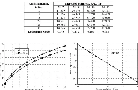
It can be found by using Eq. (2.6) that path loss at a SS positioned 1.0 km away from BS antenna of height 10 m is 136.42 dB for carrier frequency 3.5 GHz. For example, regardless of the carrier frequency, the path loss increases 38.4 dB when the distance between BS antenna and SS is extended to 10 km i.e. for M =10. Now keeping the M unaltered, this additional path loss 38.4 dB is reduced to 35.2 dB when H is increased to 30 m. Results for other values of parameters are given in Table 1. The logarithmic increase of ∆PLd with variation of M, and linear decrease of this ∆PLd when H is increased is also shown in Fig. 3.1(a) and Fig. 3.1(b) respectively.
Table 1: Variation of increased path loss (∆PLd) with distance factor and alleviating this loss by increasing BS antenna height.
Fig. 3.1(a): Variation in increased path loss with distance factor Fig. 3.1(b): Variation of increased path loss with BS antenna heigh is increased.
3.2.Compensation technique for changing transmitting frequency
Path loss is a direct function of the transmission frequency of wireless communication system. Higher frequency is associated with more path loss; hence with higher frequency a signal can travel a shorter path than that of with a lower frequency. Therefore, it significantly affects on the cell radius as well as the link budget.
Let, path loss at a lower frequency is PfL and at a higher frequency be PfH .
Antenna height, H (m)
Increased path loss, ∆PLdfor
M=2 M=5 M=10 M=15
10 11.559 26.840 38.400 45.161
14 11.366 26.393 37.760 44.409
18 11.174 25.945 37.120 43.656
22 10.981 25.498 36.480 42.903
26 10.788 25.051 35.840 42.151
30 10.596 24.603 35.200 41.398
( )
log ( ) 21log ( ) 10004 1 40 log
18
80 10 10 10 L
fL d f
H H
P +
−
+ −
= (3.2a)
( )
log ( ) 21log ( )1000 4 1 40 log
18
80 10 10 10 H
fH d f
H H
P +
−
+ −
=
(3.2b)
Then the increase in path loss is given by,
f
f
P
P
P
L H fL
fH
inc
=
−
=
21
log
10 (3.2c)Therefore, this amount of increase in path loss, Pinc should be considered for cells of different radius as well
as BS antenna of any height when the radio frequency is increased. The logarithmic increase of frequency defines the additional path loss. But considering the physical environment and shadow margin, if the link budget does not allow this additional path loss then cell radius is to be reduced. By rearranging Eq. (2.6) we can get the reduced cell radius at fH as,
+ ′
=
′ 1000
4 1 40
log 21 log
18 80
10
10 10
H
-) H (f (H) -
- L P
d (3.2d) where, PL’ = Limited path loss in link budget i.e. path loss fL and d’ = Reduced cell radius for PL’ at fH.
And percentage reduction in cell radius,
.
. d' . d
d-d'
100 0 3 0 3
100= − ×
× = %reduction
(3.2e) Where, d= cell radius at fL
Consider a SS is positioned at the edge of cell having radius of 3 km. Then by using Eq. (2.6) it can be calculated, the path loss from a BS antenna of height 15 m located in the center of cell at frequency band 2000 MHz is PL’=146.0917 dB. In our study, it is observed that in order to obtain the same cell radius in 2400 MHz band using Eq. (3.2c), an additional path loss of 1.6628 dB is required. The Pinc at other higher frequencies 2500
MHz, 2750 MHz, 3000 MHz are found 2.035 dB, 2.9043 dB, 3.6979 dB respectively.
When link budget is path loss limited, the use of higher frequency band reduces the coverage of transmission if the other parameters are kept unchanged. Further study using Eq. (3.2e) shows that the cell radius is reduced by 9.62 % from (d=3 km) to (d’=2.71 km) when the frequency band is increased from 2000 MHz to 2400 MHz to maintain the path loss 146.0971 dB.
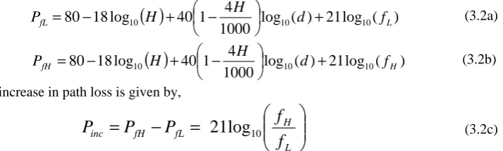
The reduced cell radius and percentage reduction at some other higher frequencies are calculated using Eq. (3.2d) and (3.2e) are summarized in Table 2 and graphical results are shown in Fig. 3.2(a) and Fig. 3.2(b).
Table 2: The increased path loss, reduced cell radius and percentage reduction of cell radius when frequency is increased from 2000MHz to other higher frequencies
Frequency ( MHz)
Increased Path Loss (dB)
Reduced cell radius ( km)
Percentage of reduction (%) 2200 0.8692 2.8445 5.1840 2400 1.6628 2.7096 9.6816
2600 2.3928 2.5911 13.6303
2800 3.0687 2.4860 17.1322
3000 3.6979 2.3921 20.2646
3200 4.2865 2.3074 23.0875
20000 2200 2400 2600 2800 3000 3200 3400 5 10 15 20 25 30 Frequency, f(MHz) P e rc en ta g e r e d u c tio n in c e ll r a d iu s ( % )
Fig. 3.2(a): The increased path loss at higher frequencies Fig. 3.2(b): Percentage reduction in cell radius at higher frequencies.
3.3.Compensation technique for changing base station antenna height
As we have discussed earlier, higher BS antenna can reduce the path loss allowing signal transmission to a longer distance. The increased BS antenna height allows extension at cell radius for a particular link budget. In this section, we have discussed the effect of increasing BS antenna height, H. To understand the nature of path loss change for increasing BS antenna height, we have introduced a parameter ‘height factor, K’.
Let, the path loss for a SS at a distance d from the BS antenna of height H be Ph and for a height HxK be Pdec.
( )
log
(
)
21
log
(
)
1000
4
1
40
log
18
80
10H
H
10d
10f
P
h
+
−
+
−
=
(3.3a)
(
)
log ( ) 21log ( )1000 4 1 40 log 18
80 10 10 d 10 f
H K
H
PhK +
− + × −
= (3.3b)
Then decrease in path loss for higher BS antenna,
(d) HK (d) H (H) K) (H P P Pdec h hK
10 10 10 10 log 1000 4 1 40 log 1000 4 1 40 log 18 log 18 − − − + − × = − = Finally,
Pdec =18log10(K)+0.16H(K−1)log10(d) (3.3c)
Therefore, the amount of decrease in path loss, Pdecbecomes independent of f but it is dependent on BS
antenna height, H from which it is increased to HxK as well as on the increasing factor, K for a definite distance between BS antenna and SS, d.
Now, this reduction in path loss can be utilized in extending the cell radius since less path loss indicates the capability of microwave signal to travel a longer distance for affixed link budget. If PL’’ is the allowable path loss in link budget when the BS antenna of height is H, then due to decrease in path loss for antenna height HxK the cell radius can be extended to d’’. By rearranging Eq. (2.6) we can get the extended cell radius as,
× + = 1000 4 1 40 log 21 log 18 80 '' 10 '' 10 10 HK -(f) K) - (H - PL
d (3.3d)
where,
PL’’ = The path loss allowed in link budget with BS antenna of height H d’’ = The extended cell radius with BS antenna of height HxK
The percentage increased in distance can be calculated as,
. d d d 100 '' × − = %increment (3.3e)
20000 2200 2400 2600 2800 3000 3200 3400
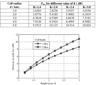
Consider a BS antenna of height 10 m is transmitting to a SS positioned at the edge of a cell having radius 2 km. By using Eq. (2.6) it is found that the path loss at this SS 142.8812 dB at 2000 MHz. It is seen that, the path loss is reduced by 5.9002 dB to 136.9811 dB when BS antenna height is increased to doubled i.e 20 m, where the height factor, K = 2.0. The results of decrease in path loss for other value of ‘K’ for cells of different radius are summarized in Table 3 and graphically shown in Fig 3.3. Note that, the BS antenna height is increased from 10m to different higher value manipulated by K.
Table 3: Decrease in path loss when BS antenna height is increased
Cell radius d ( km)
Pdec for different value of K ( dB)
K=1.4 K=2.0 K=2.4 K=3.0
1.0 2.6303 2.8230 2.9357 3.0156
2.0 3.0776 5.4185 5.9002 6.1819
3.0 6.3818 6.5369 6.8438 7.5181
4.0 7.9126 8.1924 8.4095 8.5882
5.0 9.5515 10.115 10.514 10.824
1 1.5 2 2.5 3
0 2 4 6 8 10 12
Height factor, K
D
ecr
ea
se
i
n
p
at
h
l
o
ss
(
d
B
) 1.0km
5.0km Cell Radius
Fig. 3.3: Reduction in path loss when BS antenna height is increased by factor, K.
Now for the case described above, when the antenna height is doubled (20m) the path loss is reduced by 5.9002 dB; this indicates that the RF signal reaches to SS at the edge of cell with 5.9002 dB less path loss from that of allowed in link budget. i.e. PL’’ = 142.8812 dB. Therefore, RF signal can further propagate keeping the path loss within the limit of link budget. Consequently, the cell radius can be extended from previous radius i. e. d = 2 km. By using Eq. (3.3d) and (3.3e) it is found that the cell radius is increased by 44.65% to 2.893 km when antenna height is increased from 10 m to 20 m. Thus theoretically it is possible to increase the cell radius up to 86.78% when H is increased 3 times i.e. K = 3.
4. Summary of the Results
(1) In order to maintain the predicted performance before deploying a WiMAX based communication system, it is important to keep the link budget fixed at a certain scenario. Our above analyzed results provide some mathematical formulae to achieve better and simpler solution to maintain a prescribed link budget under adverse parameters fluctuations.
(2) From our result we can conclude that, if transmission frequency is increased we need to count additional path loss that reduces the transmission capacity. Again, if cell radius is to be increased we must consider some extra path loss regardless of the transmission frequency. This additional path loss due to increasing cell radius can be easily calculated by using distance factor, M.
5. Conclusion and Future Works
In this paper, we have considered the most three parameters i.e. cell radius, BS antenna height and transmissting frequency those have a good chance to change while designing and upgrading a cellular network for WiMAX technology based communication system. The distance factor M and height factor K can give a simpler and better solution to find the required compensation for path loss and necessary rearrangements in relevant parameters.
The parameters in Walfisch-Bertoni path loss model based on ITU M.1225 Recommendationalong with city structure may also affect in path loss when above three considered parameters are under change. Therefore the new factors i.e. M, K may not give accurate result to meet new path loss in the link budget. In future more real factors and parameters may bring in simulation to get better performance in WiMAX network deployment. Taking and comparing practical data with the result got from this paper will give the accuracy of our work. References
[1] Kurratul, A and Ehtesanul I. (2010): Effect of city structure on path loss and design of cellular network for high quality video transmission in Dhaka city, Stamford Journal of Electrical, Electronic and Communication Technology, Vol. 1. Issue.3. pp. 34-39. [2] Recommendation ITU M.1225. (2002): Guidelines for Evaluation of Radio Transmission Technologies for IMT-2000.
[3] Walfisch, J & Bertoni, H, L. (1988): A theoretical model of UHF propagation in urban environments, IEEE Transaction on Antennas and Propagation. Vol 36. No 12. Pp. 1788-1796.