223
Design And Development Of Android-Controlled
Grass Cutting Robot Using RPA Method
Niño G. Herrera, Ruth G. Luciano
Abstract: This study aimed to develop an android-controlled grass cutting robot to address the problems of cutting tall perennial grasses in uneven terrain, test the feasibility of controlling the robot using android devices and to explore the ideas attaching heat and thermal sensor as a safety measure. It was developed using robotic process automation (RPA) utilized the following stages: Gather, Analyze, Design, Execute and Improvise. The grass cutting robot is controlled thru WI-FI by android app which can run in either Windows 10 with ―Bluestacks Emulator‖ or Android operating system version 4.4.2 or higher. It is armed by a grass-cutting blade made of stainless steel and it is propelled by a brushed motor. It also holds the cutting blade and brushed motor into a robotic arm that can be swiveled either automatically or manually. Its heat and thermal sensor located in the front can detect humans, mammals and birds. This sensor stops the cutting blade once detection is triggered. Other safety feature is the ultrasonic sensor which is used to detect objects that will collide into the robot and stops the robot from moving. Its steering angle, forward and reverse speed can be adjusted using the Android app.
Index Terms: android-controlled application, grass cutting robot, heat and thermal sensor, robotic process automation, ultrasonic sensor ————————————————————
1
INTRODUCTION
The grass is a very common plant that grows naturally on earth which covers up to 40% of earth‘s land surface [1]. Grasses are highly beneficial to nature and to mankind. It provides food, fuel, medicine, shelter and transportation. It provides protection against soil erosion and improves air quality and filter pollution. While grasses improve both human and animal life it can also be a pest, invasive and bringer of death and destruction. Invasive grass species when dried can cause fire. Some grass species can kill plants by choking and displacing them and competing to the soil nutrients and water resources. The invasive and uncontrollable nature of some species of grasses can greatly impact the environment and the economy [2]. In order to address these issues it needs scientific and technological solutions. The solution can either be through chemical, organic and/or mechanical means. The grass can be controlled chemically by herbicides; however herbicides cause injury to non-target plants. During the Vietnam War in 1961-1971, the Americans used the infamous herbicides called ‗Agent Orange‘ to clear vegetation in large areas of Vietnam, Laos and Cambodia [3]. It did successful defoliation but it caused huge amount of destruction to agricultural land and forest. Other forms of killing weeds is by organic means, solutions such as vinegar, dish soap, Epsom salts and borax which are low cost and can kill weeds [4]. However, most of the organic weed killers are at a much lower strength compared to the harsh chemical-based solutions and it doesn't travel down the weed and attack the root system. This means the weed can start to grow back within a short period of time. There are many manual means of controlling grasses.
These can be with the use of hoes, broad forks, rakes, and numerous other garden implements to effectively control weeds. However, many gardeners get frustrated with this method, for they wait too long to perform this task. Modern motorized lawn mowers offer convenience by reducing manual grass cutting. These machines trim the grass using its own motor power and by using its adjustable blade located on its belly. Brush cutters unlike motorized lawn mowers are held close to the body of a person and use to trim weeds which are not accessible by a lawn mower. Rot tillers or cultivators are gas powered machines armed with shanks which are frames of metal teeth used to disturb the topsoil and to uproot surrounding weeds close to crop plants. All machines specified above had issues concerning the effects of unwanted weeds or grasses in food production and the dangerous implications of neglected grass fields that can be a home for dangerous insects and wild animals which can endanger the people in facilities such as in schools and parks. And the destructive produce of invasive grass that might be the start of forest fires and wild fires motivated the researchers to conduct this study. They hoped to come up with a substitute solution or aid to manual labour which can be found in the use of battery-powered robot in which this study was focused on.
Statement of the Problem
This study sought to develop and assess an android-controlled swivel armed grass cutting robot. Specifically, it aims to answer the following questions:
1. How may the design and development of the grass cutting robot, using RPA approach, be described in terms of:
1.1 data gathering; 1.2 data analysis;
1.3 robot designing (hardware and software); 1.4 execution; and
1.5 improvization of the robot?
Conceptual Framework
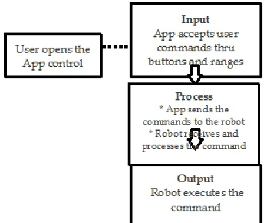
Figure 1 below shows the research paradigm. The input contains an operation where the app accepts command from the users. The app sends the command to the robot. When the robot receives the instruction, it will process and execute the command.
_________________________________________
• Niño G. Herrera is currently working as College Instructor at Nueva Ecija University of Science and Technology – College of Information and Communications Technology, Cabanatuan City, Philippines. e-mail: [email protected]
• Ruth G. Luciano is a full-time faculty of College of Information and Communications Technology at Nueva Ecija University of Science
and Technology, Cabanatuan City, Philippines. e-mail:
Figure 1.Paradigm of the Study
Figure 2, on the other hand, shows how the grass cutting robot works based on the inputs of the users. The control elements in the Android app is composed of label, ranges (or sliders) and button controls. The label shows the robot‘s control and status. The control buttons are used to control the robot‘s movement either forward, backward; steer, center, left, right and brake. There are also buttons that can automatically adjust the robot‘s arm vertically while the other buttons are used to turn on and turn off the cutting blade. The proposed model of grass cutting robot has a robotic arm holding the grass cutting blade that can swivel left and right to maximize its use. The robot can be controlled thru WI-FI by an App installed in a smart phone, tablet, PC and so on.
Figure 2. Android-Controlled Grass Cutting Robot
Figure 3. Thru heat/thermal and ultrasonic sensors the robot has the ability to detect obstacles and warm-blooded creatures
which when detected, the robot will stop its operations.
2
METHODOLOGY
Research Design
In order to transform the idea into reality, developmental method of research was used in this study. The researchers examined and studied the different types of lawn mowers and grass cutting robots commonly used in homes, sports fields and farms. Robotic Process Automation (RPA) approach was utilized in the design and development of the Android-controlled grass cutting robot. It is defined as the use of software with artificial intelligence (AI) and machine learning capabilities to handle high-volume, repeatable tasks that previously required humans to perform [5].
Procedures of the Study
This study is of two stages: development and assessment.
1. Development Stage
The nature of this study is similar to software development which involves constructing, developing and improvement of the product. The researchers used the Robotic Process Automation (RPA) method. In this method, the management of a project caters to all aspects of discovery, analysis, design, implementation and support. Steps in the RPA methods are shown in Figure 4 below.
2. Assessment
After the development of the system, it was subjected to many trials and were tested in proving grounds and evaluated by IT experts and professional users using ISO 25010 standards. Data received from this period were organized and interpreted and had been used as bases of the assessment of the proposed system.
3. Analysis of Data
The ratings of the respondents were calculated and translated into qualitative and describable meanings.
Figure 4.Robotic Process Automation Method
3
RESULTS
AND
DISCUSSION
1.
Gather225 alibaba.com among others. Some of the products searched by
the one of the researchers from these online retail stores provided detailed information like customer reviews and ratings. Some products do not have the details but provided the website of the manufacturers; hence, the manufacturers‘ websites were visited. The details and performance of its products were gathered through this process. Aside from google and image searches, the other technique used in this study is the youtube video sharing sites. YouTube videos allowed the researchers to view not only the capabilities and performance but also the viewer‘s comments, likes and dislikes. They also used yahoo search engines to find information not available from Google search. Sometimes lawn mower companies provide Adobe PDF brochures,
catalogues and presentations. These items were also collected, examined and used by the researchers.
2.
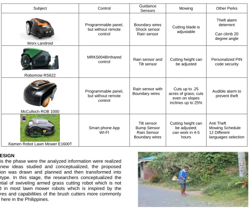
AnalyzeInformation from robotic lawn mowers or grass cutting robots were organized and collated. The idea was to find out the functions, strengths and limitations of the gathered information to create a new design. One of the researchers itemized the collected information into a table. Categorizing the information in this manner enabled them to easily examine, evaluate, compare and understand the various robotic lawn mowers. Table 2 below shows how the researchers analyzed the collected data.
Table 2. Sample Table Used in the Analysis Phase
Subject Control Guidance
Sensors Mowing Other Perks
Worx Landroid
Programmable panel, but without remote
control
Boundary wires Shock sensor
Rain sensor
Cutting blade is adjustable
Theft alarm deterrent
Can climb 20 degree angle
Robomow RS622
MRK5004BInfrared
control Rain sensor and Tilt sensor
Cutting height can be adjusted
Personalized PIN code security
McCulloch ROB 1000
Programmable panel, but without remote
control
Rain sensor with Boundary wires
Cuts up to .25 acres of grass; cuts
even on slopes inclines up to 25%
Audible alarm to prevent theft
Xiamen Robot Lawn Mower E1600T
Smart phone App WI-FI
Tilt sensor Bump Sensor
Rain Sensor Boundary wires
Cutting height can be adjusted; can work in 4-5
hours Anti Theft Mowing Schedule 12 Different languages selection
3.
DESIGNThis is the phase were the analyzed information were realized into new ideas studied and conceptualized, the proposed solution was drawn and planned and then transformed into prototype. In this stage, the researchers conceptualized the potential of swiveling armed grass cutting robot which is not found in most lawn mower robots which is inspired by the features and capabilities of the brush cutters more commonly used here in the Philippines.
Figure 5. Brush cutter is the basis and inspiration in designing the proposed system.
few robotic grass cutting machines can do cutting tall perennial grasses, the gas powered heavy duty remote controlled robots like Kawasaki commercial engine mower can do these easily because of its size and motor power. The brush cutters despite of its simplicity can cut tall perennial grasses not only because of its powerful motor but because its blade is exposed. These ideas were used as additional bases in conceptualizing and designing the proposed system.
3.1 Hardware
The android-controlled swivel armed Grass Cutting Robot‘s initial design and the first model is named Grass Cutting Robot Mark I model (GCR-1A). It is grass cutting robot propelled by caterpillar tracks powered by electric motor. This model is used as a prototype model. This is used for testing and demonstration purposes. The tracked vehicles can cross and handle steep and difficult terrain just like the bulldozer used in construction business.
Figure 6. Artistic rendition of GCR-1A
The GCR-1A has a heat or thermal sensor that is used to detect warm beings and stop its blade when detection is in range. Ultrasonic sensor, used to detect collision, is located in front including the two small metal geared servos. These metal geared servos are used to propel and handle the robotic arm vertically and horizontally. The GCR-1A also has webcam to allow the user to remotely view the activity of GCR-1A. This webcam is installed in the robot but not directly connected to it. This means that the webcam is independent and not controlled by the robot. The user has to manually connect to the webcam for viewing and then connect to robot‘s web based control interface. Autonomous capability of GCR-1A is implemented thru its Global Positioning System (GPS) module. This module has recorded waypoints for GCR-1A. Electronic components such as wires and microcontrollers were installed inside the caterpillar rover. The battery was installed at the bottom of the caterpillar rover.
Figure 7. Parts of GCR-1A
Figure 8. Robotic arms of GCR-1A.
The GCR-1A has the ability to swivel horizontally or position its arm 40 degrees left, 90 degrees center or 140 degrees right. It can also position its robotic arm vertically from 50 degrees up and 130 degrees down.
3.2 Software
The initial experimental control software for GCR-1A is a web-based control interface. This interface interacts thru Wi-Fi to communicate to the robot. The idea of this prototype is to find out if this control platform is feasible and compatible to devices such as smart phones, tablets, desktops and laptops. Other reason of the development of this web interface is to find out if a browser or an app is needed to handle its process. The web interface sketch was created using Hypertext Markup Language (HTML) and JavaScript.
4.
EXECUTE
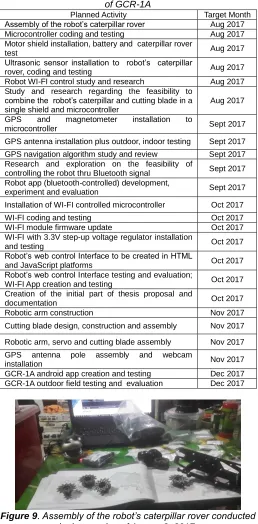
227 Table 3. List of Planned and Executed Activities
of GCR-1A
Figure 9. Assembly of the robot’s caterpillar rover conducted in the evening of August 2, 2017.
Figure 10. Ultrasonic sensor installation, coding and testing of robot’s caterpillar rover conducted on August 17, 2017.
Figure 11. GPS and magnetometer installation to microcontroller conducted on September 2, 2017.
Figure 12. Also conducted on September 2, 2017 was the GPS antenna installation. Outdoor and indoor testing were
also implemented during this period.
Figure 13. Experimental app is first studied in Android studio and developed in MIT App maker. It was designed to find out if
the robot will respond to Bluetooth commands. This Bluetooth App failed to control the robot due to GPS+GPRS+GSM shield
firmware and the incompatibilities of the Bluetooth of both robot and computer. Hence, this program was abandoned. This experiment was conducted from September 24 to 25,
2017.
Figure 14. Installation, wiring and testing of WI-FI module ESP8266 together with 3.3v step-up voltage regulator
completed around first week of October 2017. Planned Activity Target Month
Assembly of the robot‘s caterpillar rover Aug 2017 Microcontroller coding and testing Aug 2017 Motor shield installation, battery and caterpillar rover
test Aug 2017
Ultrasonic sensor installation to robot‘s caterpillar
rover, coding and testing Aug 2017
Robot WI-FI control study and research Aug 2017 Study and research regarding the feasibility to
combine the robot‘s caterpillar and cutting blade in a single shield and microcontroller
Aug 2017
GPS and magnetometer installation to
microcontroller Sept 2017
GPS antenna installation plus outdoor, indoor testing Sept 2017 GPS navigation algorithm study and review Sept 2017 Research and exploration on the feasibility of
controlling the robot thru Bluetooth signal Sept 2017 Robot app (bluetooth-controlled) development,
experiment and evaluation Sept 2017
Installation of WI-FI controlled microcontroller Oct 2017
WI-FI coding and testing Oct 2017
WI-FI module firmware update Oct 2017 WI-FI with 3.3V step-up voltage regulator installation
and testing Oct 2017
Robot‘s web control Interface to be created in HTML
and JavaScript platforms Oct 2017
Robot‘s web control Interface testing and evaluation;
WI-FI App creation and testing Oct 2017 Creation of the initial part of thesis proposal and
documentation Oct 2017
Robotic arm construction Nov 2017
Cutting blade design, construction and assembly Nov 2017
Robotic arm, servo and cutting blade assembly Nov 2017 GPS antenna pole assembly and webcam
installation Nov 2017
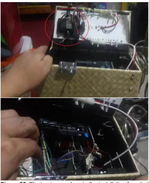
On October 7, 2017 the robot‘s web-based control interface was created and tested. The test was partially successful. The robot was responding to the commands, however, the webpage was encountering a ―Page cannot be displayed error‖ due to broken links. This error appeared in every command which proved that web- based control is unstable. Hence, the design and creation of much stable and feasible android app was planned in November or December 2017. The WI-FI module testing and evaluation done in October 2017 encountered a lot of errors. The WI-FI module was responding but after 5 or 10 minutes it disconnected itself. It was found out that the wires and the breadboard connections and the battery supply caused the erratic behavior of the said module. Other issues found during the activity were the exposed wires and the exposed microcontrollers located at the top of the robot. Because the electronic components were overcrowded by wires the whole system was not fit inside the robot. Additional problems rose with the added components such as heat/thermal sensor which was not yet installed during this period. Additional problems might occur and cause a lot of confusion making the maintenance of the robot‘s interior difficult and time consuming. Thus, the sensor was placed on top of the robot. But this setting made the electrical component highly vulnerable to outside environment such as sunlight or rain.
Figure 15. Initial experimental Android App that uses WI-FI instead of Bluetooth.
5.
IMPROVISE
In this stage the findings of the prototype‘s inadequacies were re-engineered, re-designed, improved and tested. A new design was created to address the issues found during the execution phase. Despite of delays caused by maintenance and errors, the plan was adjusted to cater additional activities which will help improve the performance of the system.
Figure 16. Improvisation of GCR-1A transforming it into enhanced design which is called as GCR-1B.
Because of the increasing number of wires and electrical components, a box was designed as container of the system‘s hardware. There was also a realization that a webcam is unnecessary in robot‘s field operation because it is being controlled directly and operated in short ranges. The robot‘s designation is renamed as GCR-1B or Grass cutting Robot Mark 1 Model B designed in late October 2017.
Figure 17. Construction of Robotic arms began on Nov. 24, 2017.
229 Figure 19. GPS Antenna pole construction and installation
began on November 24, 2017.
Figure 20. Installation and testing of ceramic capacitors into robot’s rover electric motor. The ceramic capacitors will act as
an electrical noise absorber to reduce its interference to robot’s WI-FI and GPS signals. Installation and testing
occurred on November 25, 2017.
Figure 21.Improving the robotic arm of GCR-1B
During the testing, it was found out that the cutting motor was heavy and cannot be handled by a single servo. The robotic arms were redesigned to accommodate two (2) servos to lift the cutting motor.
Figure 22. Preparation of the cardboard patterns for the robotic arms’ cutting blades, battery hatch and servo hatch
(top). Tinsmith’s stainless steel conversion of the design patterns (bottom).
Figure 24. Battery hatch installation at the bottom of the robot.
Figure 25. Installation of robotic arm and counterweights (or hinges) to the robotic arm held on December 8, 2017.
Figure 26. Electronic speed controller installation for robot’s cutting blade motor; installed on December 12, 2017.
Figure 27. GCR-1B improved electrical layout.
231 Figure 28. Testing of caterpillar rover, robotic arm servo and
cutting motor. The test was conducted on December 17, 2017. The test severely damaged the robot’s motor because it could not handle heavy load.
Figure 29. On December 18, 2017 because of the size of caterpillar rover and its weakness to handle heavy loads, the robot’s transport rover was replaced with a 4x4 Tamiya rover. The new design was named as grass cutting robot Mark II Model A (GCR-2A).
Figure 30. Construction of GCR-2A on December 22, 2017.
The Motor Shield was removed and replaced by additional motor driver (aka ESC) to manage the rover.
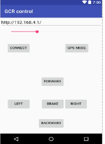
Figure 31. Android WI-FI controlled App creation; testing and modifications, conducted from January 1 to January 9, 2018.
Figure 32. GCR-2A with improved electrical layout
Because of the unreliability and complexity of ESP8266 WI-FI module, it was replaced with a much simpler and stable ESPDuino+ESP8266 microcontroller. Arduino Mega and Arduino Uno became a slave to ESPDuino+ESP8266.
Figure 34. Outdoor testing of GCR-2A was also conducted on January 10, 2018
Figure 35. Cutting blade installation and partial field test at Kapitan Pepe Subdivision, Phase 2, Cabanatuan City,
Philippines was done on January 23, 2018.
From February to March 2018, additional enhancements, final field trials and assessments were made. Improvements on design such as installation of trimmer guard and additional box container are implemented. Other changes were also made in re-designing the application. Problems such as frequent motor hiccups and control delays were greatly reduced.
Figure 36. The screenshot of the new App can be seen in the above figure. Security window (left) and main control window
(right) ranges or sliders were replaced by textboxes.
On March 7, 2018, background picture was removed from the app and the sliders objects were replaced by textboxes. Eventually, new progress has been noted when App security
has been established. This feature asks the user to type his/her username and password before entering the system. Another feature added to the app is the sensitivity input to heat sensor detection; it allows the user to adjust the triggered temperature for the heat/thermal sensor.
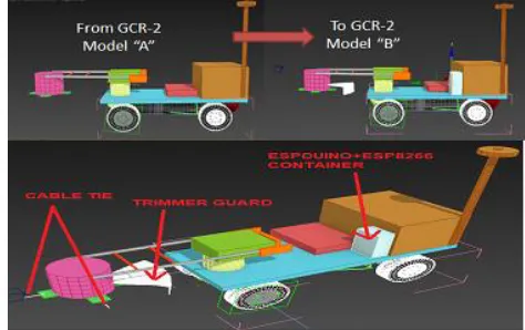
Figure 37. New design of grass cutting robot named as Grass Cutting Robot model “B” (GCR-2B).
On March 8, 2018, the new design of grass cutting robot was implemented. The new design includes cable tie for cutting blade and trimmer guard. There is also a LED indicator to tell if ―safety on‖ is activated. Another noticeable feature in the design is the addition of plastic container for ESPDuino+ESP8266 WIFI microcontroller, Because of these additional enhancements the robot is now called as Grass Cutting Robot model ―B‖ (GCR-2B).
Figure 38. Formation of the newly designed GCR-2B, installation of “safety on” LED (extreme left), partial construction of trimmer guard (center left), Cable tie installation (center right) and installation of ESPduino
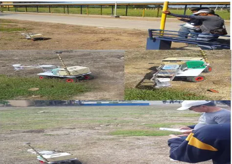
233 Figure 39. Professional users testing, field trials and
assessment held at NEUST Sumacab Campus, Cabanatuan City, Philippines.
Figure 40. Added enhancements and installation of trimmer guard
Figure 41. IT experts and additional professional users’ system testing and assessment.
During the system testing at the NEUST Sumacab Campus proving grounds, the robot‘s control responded well to the commands. It performed its job to cut grasses. It can also move forward, turned left, turned right, turned center, brake and then move backwards. The speed adjustment does its job
well; it navigates the uneven terrain. But by the time it encountered deep ravines and large pot holes, the robot started to have difficulties due to its balance and weight. The developer, then, adjusted the speed and it then climbs slowly. In another setup, the robot was placed in small mountainous terrain. The robot encountered a very steep ground on its port side which made the robot to tumble sideward. This event battered the robot which then causes the robot to slightly misbehave. While doing a grass cutting test the auto-swivel feature is working; however, its old problem of blade slowing down was encountered. Another terrain test was made and despite of very small hiccups caused by sideward tumble, the robot passed the terrain successfully. But while it is travelling it encountered a high angled steep terrain which was in the port side of the robot. This caused the robot to tumble again. The robot was then diagnosed and repaired and found out that there are loosed wires which cause the problem. These experiences lead to an idea that a wider rover chassis with wider double wheels are needed so that the robot can learn to balance itself.
4
CONCLUSION
Based on the findings, the following conclusions are drawn: The ―Android-Controlled Swivel Armed Grass Cutting Robot‖ called GCR-2B was successfully developed using Robotic Process Automation (RPA) with the following stages: Gather Analyze, Design, Execute and Improvise.
Based on the salient findings of the study, the following recommendations are offered:
1. Research on robot‘s multitasking capabilities is suggested such as a study on raspberry pi computer which is a better alternative for Arduino microcontrollers.
2. Inclusion of additional safety features such as rain detection and protection, LED indicators and gyroscopic stabilization is recommended.
3. Use of object recognition cameras to detect and distinguish humans, animals and obstacles can also be considered.
4. Other security features recommended are anti-theft alarm and GPS homing device with SMS messaging capability. 5. Follow-up study evaluating the quality of the GCR-2B
using ISO 25010 is recommended.
5
ACKNOWLEDGMENT
The authors wish to acknowledge and extend their sincere appreciation to the: (1) participants of this study; (2) College of Information and Communications Technology and (3) Graduate School – MSIT program. They would also like to extend their profoundest gratitude to all those who had, directly and indirectly, contributed in the conduct of this noble undertaking.
6 REFERENCES
[1] Gibson, DJ (2009). Grasses and Grassland Ecology. New York: Oxford University Press.
[2] National Wildlife Federation. The Invasive Species. https: //www.nwf.org/Educational-Resources/Wildlife-Guide /Threats-to-Wildlife/Invasive-Species. Date retrieved: January 7, 2020.
[4] Pros and cons of vinegar as a weed killer. http://pioneer thinking. com/pro-and-cons-of-vinegar-as-a-weed-killer
[5] Robotic process application (RPA). https://internetoft