Design and optimization of full decoupled
micro/nano-positioning stage based
on mathematical calculation
Zhigang Wu1, Yangmin Li2, and Min Hu1 1The School of Energy and Machinery Engineering,
Jiangxi University of Science and Technology, Nanchang 330013, China
2Department of Industrial and Systems Engineering,
The Hong Kong Polytechnic University, Hong Kong, Hong Kong
Correspondence:Zhigang Wu ([email protected])
Received: 11 July 2018 – Revised: 4 November 2018 – Accepted: 12 November 2018 – Published: 21 November 2018
Abstract. Nano-positioning is widely used in Micro-electromechanical Systems (MEMS), micromanipulator and biomedicine, coupling errors and tiny output displacements are the main disadvantages of the one. A totally uncoupled micro/nano-positioning stage with lever amplifiers is designed and tested in this paper. It is fully symmetrical along with thex- andy-directions. For obtaining large output displacements, two fully symmetric two-stage lever displacement amplifiers are utilized to amplify output displacements of piezoelectric actuators (PZTs). The established models for performances evaluation of the stage, in terms of kinetostatics, amplification ratio, reachable workspace, the input and output stiffness, are verified by finite element analysis (FEA). After that, the dimensional optimization is also carried out through the genetic optimization algorithm.The prototype of the mechanism is fabricated by using Wire-Electrical-Discharge-Machining (WEDM) process. Testing results indicate that the proposed micromanipulator demonstrates good performance.
1 Introduction
Flexible hinge, which possesses these advantages of no back-lash, no friction, simple structure, and easy manufacture, is widely applied in the micromanipulation system includ-ing micro/nano-positioninclud-ing stages, micromanipulators, and high-accuracy alignment instruments (Tian et al., 2009). Mi-cromanipulation system has been paid more and more atten-tion in recent years, especially the parallel compliant mech-anisms own some inherent advantages as big load capacity, high velocity, and high precision compared with serial ones (Dong et al., 2016). Piezoelectric actuators (PZTs) are usu-ally selected as the actuators of the compliant mechanisms due to these advantages of fast response and high precision (Yong et al., 2009). Unfortunately, small output displace-ments of the PZTs and cross coupling motions of the end-effector have badly restricted the further application (Yu et al., 2011) and development of the compliant mechanisms (Yu et al., 2015).
At present, some amplifiers between the actuator and mo-tion stage have also been proposed to overcome the disadvan-tage of small output displacement. Such as the lever displace-ment amplifiers (Tang and Li, 2015) and bridge-type ampli-fiers (Wu and Li, 2014) are commonly used as the bridge for amplifying the output displacements.
Cross coupling of compliant mechanisms at x- and y -directions is an inevitable property in parallel mechanism (Dong et al., 2007). It can seriously influence the precision of motion (Hao et al., 2016). The 2-degree-of-freedom (2-DOF) compliant stages include two types of structure: One is in series and another is in parallel (Fan et al., 2018). For example, Lin and Lin (2012) have designed a series ofxy
compliant mechanisms with the maximal cross coupling er-ror of 0.12 µm and the frequency of 50 Hz. Additionally, Polit and Dong (2011) have also proposed a high-bandwidthxy
et al. (2015) have also designed a novelxyparallel compli-ant mechanism with the first natural frequency of 763.23 Hz more than other papers.
Based on the aforementioned analyses, the micromanipu-lation stage is proposed in this paper with low cross coupling, large reachable workspace, high stiffness and high band-width. It aims to improve the positioning precision of mi-cromanipulator. The theoretical calculation, simulation anal-ysis, and prototype tests demonstrate that the presented 2-DOF micromanipulator with mechanical amplifiers owns the performance for cross coupling error of under 0.1 % at the full range of 169.6 µm×165.3 µm, with the frequency of 348.31 Hz, which can be used in high frequency position-ing micromanipulation system. Additionally, the positionposition-ing system will be controlled easily by reducing the coupling er-rors, which have the important applying value in the field of micro-nano manufacturing platform or micro 3-D printing system combining with the micro gripper. The main contri-bution of this paper is described as follows: (a) the struc-tural design, kinematics and statics modeling analysis, and prototype test of this novel mechanism; (b) the lower cross coupling errors with larger workspace compared with other papers.
The remainder of this paper is organized as follows. The concept of mechanical amplifier and the process of mecha-nism design is described in Sect. 2. Then in Sect. 3, the kine-matics and dynamics analyses of the mechanism with am-plification ratio, stiffness, reachable workspace and natural frequency are presented in details. Besides, the performance evaluation and model verification implemented by the finite element analysis (FEA) are conducted in Sect. 4. Afterwards, structure optimization is carried out through genetic opti-mization algorithm in Sect. 5. Furthermore, prototype fabri-cation and performance tests are presented in Sect. 6. Finally, the conclusions and future work are presented in Sect. 7.
2 Structural design
2.1 The concept design of lever amplifier
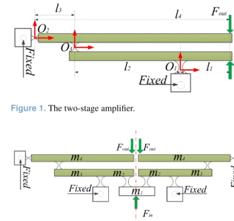
Lever amplifier based on flexure hinges possesses the advan-tages of high amplification ratio and simple structure (Choi et al., 2007). A two-stage amplifier is shown in Fig. 1.
According to the mechanical principle, supposing that an outside force Fin is applied at free-end, the corresponding deformation displacement is δ. Therefore, output displace-mentsdoutandδoutare obtained. Considering Fig. 1, it can be observed that the two-stage amplifier is composed of two one-stage amplifiers. Assuming that the input displacement of two-stage magnifier is alsoδ, the total theoretical magni-fication ratio can be written by
Figure 1.The two-stage amplifier.
Figure 2.Symmetrical structure with two 2-stage amplifiers.
AR=AR1×AR2= l2 l1×
l4
l3 (1)
For enhancing the input stiffness, the parallel structure is used as an amplification mechanism for amplifying the input displacement as shown in Fig. 2. The mechanism is fully symmetric along with the central line and is connected by two amplifiers in parallel. The symmetrical structure of input-end of the mechanism can protect the PZT from dam-age.
2.2 2-DOF positioning stage
To eliminate cross coupling of the end-effector, symmetrical 1-DOF structure is shown in Fig. 3, where the double four-bar parallelogram mechanism is designed to connect the mo-tion stage. The 4P-joint is composed of the four prismatic joints.
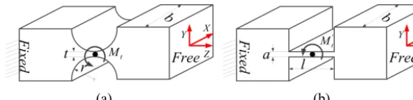
Simplified principle diagram of the 2-DOF positioning stage is presented as shown in Fig. 4, where the four me-chanical displacement amplifiers and two double four-bar parallelogram mechanisms are utilized to design a fully sym-metrical mechanism along withx- andy-directions. Particu-larly, the vertical distribution structure of two double four-bar mechanisms can effectively decrease cross coupling.
Figure 3.1-DOF symmetrical mechanism.
Figure 4.Simplified principle diagram of mechanism.
reduced or even eliminated. Circular hinges are adopted in the mechanical amplifier to avoid the parasitic motions.
3 Kinetostatics and dynamics modeling analysis
There are many modeling methods to analyze the kinematic performance of compliant mechanism, such as the numerical model method, the pseudo-rigid-body (PRB) model method, and the compliance matrix model method (Tang and Li, 2013). In this section, kinetostatics and dynamics modeling of the compliant mechanism, including the amplification ra-tio (AR), input stiffness, reachable workspace and natural frequency, are analyzed by the numerical modeling method and Lagrange’s method.
Figure 5.The 3-D diagram of the 2-DOF compliant mechanism.
3.1 Amplification ratio and input stiffness analysis
Firstly, the amplification ratio and input stiffness of the mechanism are analyzed. The flexure circular notched hinge can be regarded as the general spring with bending stiff-ness (kb) created by lateral force, torsion stiffness (kt) caused
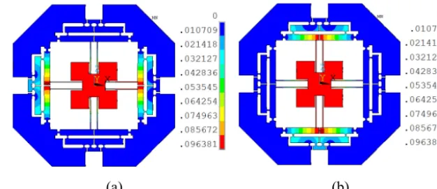
by the torque and linear stiffness (kl) produced by the ax-ial force. Additionally,kt0andkl0are the torsion stiffness and linear stiffness of the prismatic beam (Koseki et al., 2002). Therefore, the rotational and linear deformations may simul-taneously occur when a force is applied at the free-end of the beam. As shown in Fig. 6, the simplified diagrams of the cir-cular notched hinge and prismatic beam are presented. Addi-tionally, the torqueMtis produced after a small deformation
angle1θoccurs along with the center of the hinge from in-side of the flexure hinge. Therefore, stiffness of different di-rections for flexure hinge can be represented in the following equations:
kt=
2Ebt2.5
9π r0.5 , kt
0=Ea3b
12l ; kl=
Ebt0.5
π(r0.5−0.5t0.5), kl
0=Eab
l ;
kb=
2Ebt2.5
3π r1.5(3r+t), Mt=kt1θ;
(2)
whereEis the elastic modulus,bis the thickness of the flex-ure hinge, r andt are radius and smallest thickness of the circular notched hinge,a andl are the width and length of the prismatic beam, respectively.
(a) (b)
Figure 6.The flexure hinges:(a)the circular notched hinge;(b)the prismatic beam.
δout=λARδin (3)
Fin=Kinδin (4)
whereλARandKinare the amplification ratio and input
stiff-ness of the micromanipulator, respectively.
Due to the symmetry, only half of the amplifier mecha-nism is analyzed. According to the assumptions of literatures (Su and Yang, 2001a), force analysis simplified diagrams of the mechanical amplifiers are drawn up as shown in Fig. 7, where the Fig. 7b and c are two kinds of different one-stage amplifiers (Su and Yang, 2001b). Therefore, in consideration of the force and moment balance at the equilibrium state of the beam 2, the following equations can be derived as
FO3y=FO2y+FBy (5)
FO3yl3=FByl4+2Mt+Mt
0 (6)
whereMtandMt0are bending moments of the pointsO2and
B. Additionally, the forcesFO2y andFBy can be calculated through multiplying stiffness by displacement. They are ex-pressed by the following formulas
FO2y=kO2yδ2, FBy =kBl(l4θ2+δ2) (7) Mt=kO2tθ2, Mt0=kBtθ2 (8)
wherekO2yandkBlare the lateral bending stiffness caused by
forceFO2y and output stiffness of the pointB, respectively. kO2tandkBt are the rotational stiffness of the pointsO2and B.
Substituting Eqs. (7) and (8) into Eqs. (5) and (6), theθ2
andδ2can be derived as
θ2= (kO2y+kBl)l3−kBll4 (kO2y+kBl)(kO2t+kBt)+2kO2ykBll
2 4
FO3y (9)
δ2= kO2t+kBt+kBll
2
4−kBll3l4
(kO2y+kBl)(kO2t+kBt)+2kO2ykBll 2 4
FO3y (10)
Therefore, the amplification ratio and input stiffness of the beam 2 can be calculated by the following equations
λ2=l4θ2+δ2
l3θ2+δ2 (11)
kin2= FO3y
l3θ2+δ2
(12)
Then, substituting Eqs. (9) and (10) into Eqs. (11) and (12), following formulas can be obtained as
λ2=
kO2yl3l4+2kO2t+kBt kO2yl
2
3+2kO2t+kBt+kBl(l4−l3)2
(13)
kin2=(kO2y+kBl)(2kO2t+kBt)+kO2ykBll
2 4 kO2yl
2
3+2kO2t+kBt+kBl(l4−l3)
2 (14)
Similarly, considering the relationship of force and mo-ment balance at the equilibrium state for the beam 1 as shown in Fig. 7b, the following formulas can be obtained by
FO3y+FAy =kO1lδ1 (15)
FAyl1=FO3yl2+kO3tθ1+kO1tθ1 (16)
FO3y=k2(l2θ1−δ1) (17)
wherekO1landkO1tare axial stiffness and rotational stiffness
of the pointO1; kO3t is rotational stiffness;k2 is proposed
as the stiffness of the series connection between the flexure hingeO3and the beam 2, which can be expressed by
k2= kin2kO3l kO3l+kin2
(18)
wherekO3lis axial stiffness of the flexure hingeO3.
Combin-ing the Eq. (15) into Eq. (18), theθ1andδ1can be calculated
by
θ1= kO1ll1+k2(l1+l2) (kO3t+kO1t)(kO1l+k2)+kO1lk2l
2 2
FAy (19)
δ1= kO3t+kO1t+k2l
2
2+k2l1l2
(kO3t+kO1t)(kO1l+k2)+kO1lk2l 2 2
FAy (20)
Therefore, according to the Fig. 7b, amplification ratio and input stiffness of the beam 1 can be represented by
λ1=
l2θ1−δ1
l1θ1+δ1 (21)
kin1= FAy
l1θ1+δ1 (22)
Substituting Eqs. (19) and (20) into Eqs. (21) and (22), they can be rewritten by
λ1= kO1ll1l2−(kO3t+kO1t)
kO1ll 2
1+kO1t+kO3t+k2(l1+l2)2
(a) (b)
(c)
Figure 7.Force diagram:(a)the deformation of the half of the amplifier;(b)forced diagram of beam 1;(c)Forced diagram of beam 2.
kin1=(kO1l+k2)(kO3t+kO1t)+kO1lk2l
2 2 kO1ll
2
1+kO1t+kO3t+k2(l1+l2)2
(24)
Consequently, the total amplification ratio of the two-stage lever displacement mechanism is calculated by
λAR=λ1λ2 (25)
Additionally, total input force can be obtained by Fin=
2FAy, since the amplifier is symmetric and is connected in parallel. Therefore, input stiffness can also be calculated by
kin= Fin
l1θ1+δ1=
2FAy
l1θ1+δ1=2kin1 (26)
For calculating the values ofkinandλAR, the stiffness (kBl)
of the output pointBmust be firstly computed. According to the Fig. 4, it can be observed that the output stiffness of the micromanipulator is the stiffness of components except from the driven amplifier. Simplified diagrams of output compo-nents are shown in Fig. 8 when the platform is driven in y -directions. The marked signs, kl0 andkt0, are axial stiffness and rotational stiffness of the prismatic beam, respectively. Andk1is the input stiffness of the two-stage amplifier when the input-end is at the pointBand output-end is at the point
Aas shown in Fig. 7a.
Output displacement of the mechanism, dout, can be
ob-tained when an input displacement din is applied at y
-direction, whereas the amplifier of the x-direction will still hold since they have large transverse stiffness (Tang and Li, 2014). In addition, all rotational angles of the prismatic beams, (θ), are the same due to the identical structure. The potential energy stored in the flexible hinges can be derived as follows:
Pout=1 2kNd
2 out
=4×1 2kt
0
(θ)2+2×1 2kt(α
2 1+2β
2 1+γ
2
1) (27)
whereα1,β1andγ1are rotational angles of flexible hinges
of the amplifier and can be written by
θ= dout
l5 2
, α1= dout
l4 2
;
β1= d
out
3l2 2
, γ1= d
out
5l1 2
; (28)
As shown in Fig. 8b, the stiffnesskNcan be achieved by
kN= 4kt0
l25
+2kt 1 l42
+ 2 9l22
+ 1 25l12
!
(29)
According to the series-parallel relationship of the mech-anism, the output stiffnesskoutcan be expressed by the
fol-lowing formula
kout= kNka
kN+ka
= 4kl
0k
t0+2ktkl0l52M kl0l52+2kt0+ktl52M
(30)
whereM= 1 l2 4
+ 2
9l2 2
+ 1
25l2 1
,kt0andkl0are rotational stiffness
and axial stiffness of the prismatic beam.
Because circular notched hinges and prismatic beams used in this study are identical, thus their stiffness can be ex-pressed by
kO1t=kO2t=kO3t=kAt=kt kO1l=kO3l=kl
kO2y=kb kBt =kt
0
(31)
Due to the symmetry of the mechanism, the stiffnesskBl
can be obtained by
kBl =0.5kout (32)
(a) (b)
Figure 8.The stiffness of output mechanism:(a)the diagram of the output mechanism;(b)the output stiffness transformation diagram.
Table 1.Geometric parameters (mm) and properties of material of
the mechanism.
r t a b l1 l2 l3 l4 l5
1.5 0.5 0.5 10 7.5 12.5 10 30 30
E ε ρ σy
71.7 GPa 0.33 7810 kg m−3 503 MPa
3.2 Reachable workspace analysis
For a 2-DOF motion platform, supposing that the ARm is
denoted as the amplification ratio of the mechanism andSis looked as the stroke of the PZT actuator, the workspace of the micromanipulation stage is represented by ARmS×ARmS. In this study, the bending stress only occurs on the cross sec-tion of flexible hinge when axial tension and shearing effects are not taken into consideration. Thus stress (σr) can be cal-culated as the following equation:
max{σr} ≤ σy
s (33)
whereσyands >1 are the yield strength and the safety fac-tor of the material. In addition, maximal stressσrmaxoccurs when the angular displacementθmaxis maximum. It can be expressed using the following formula
σrmax=4Er
2kc
f(β)t2θmax (34)
wherekcandf(β) are the dimensionless concentration factor
and compliance factor, respectively. They are expressed by (Smith, 2000).
kc=(1+β)9/20 (35)
f(β)= 1 2β+β2
3+4β+2β2
(1+β)(2β+β2)+
6(1+β) (2β+β2)3/2tan
−1 s
2+β β
!
(36)
whereβ=t /2ris the dimensionless geometry factor. Assuming that the maximal input displacement is δinmax, corresponding to the output displacement of the motion stage isλARδinmax. According to the mechanical principle, the
max-imal stress may occur on the hingeO3 connecting the two
lever beams, since it not only suffers from the angular de-formation created by output displacement, but may be also subjected to the angular deformation produced by the input displacement. Therefore, the maximal deformation angle can be derived by
θmax=
λARδmaxin l4
+λ1δ
max in l2
(37)
Substituting Eqs. (37) into (34) and considering the Eqs. (36) and (33) at the same time, the maximal input dis-placement can be calculated as follows
δinmax≤ l2l4t
2f(β)σ y 4Er2k
cs(l2λAR+l4λ1)
(38)
Substituting values of the Table 1 into the Eq. (38) and letting the safety factor be 1.78. Maximal input displacement can be calculated as follows
δinmax≤49.2 µm (39)
Considering the amplification ratio of the mechanism, the output displacement of the stage can be 236.2 µm. Due to the symmetry of the mechanism, so the reachable workspace of the platform can be expressed as 236.2 µm×236.2 µm.
3.3 Natural frequency analysis
(a) (b)
Figure 9.Deformations:(a)input atxdirection and(b)input atydirection.
to describe the motions ofx- andy-axes. The kinetic energy (T) and potential energy (V) stored in the mechanism can be expressed by the selected generalized coordinate and their derivations (Li et al., 2013). And then, substituting the kinetic and potential energies into the following Lagrange’s equation
d dt ·
∂T ∂η˙i
−∂T
∂ηi +∂V
∂ηi
=Fi (40)
wherei=1,2, corresponds to the free vibration of x- and
y-directions of the stage.
Mη¨+Kη=0 (41)
where the equivalent massM=diag{M}and stiffnessK= diag{k}are the 2×2 diagonal matrices, along with
M=2m0λ2AR+4m1+7 3m2+
7 3m3λ
2 1
+7 3m4λ
2 AR+
16 3 m5λ
2
AR (42)
K=kin (43)
wheremi(i=0,1, . . .,5) are shown in the Figs. 2 and 5. Solving the Eq. (41), the natural frequency of the stage can be obtained as
f = 1 2π
K
M 0.5
(44)
which has the unit of Hertz.
4 Verification and evaluation with FEA
In this section, the established models to evaluate the prop-erties of the 2-DOF micromanipulation stage on aspects of amplification ratio, input stiffness, reachable workspace, and natural frequencies are verified by using FEA software (Li et al., 2012).
4.1 Model verification
For analyzing the amplification ratio of the proposed mech-anism, an input displacement with 20 µm is separately pro-vided in thex- andy-directions and the deformation of the mechanism is shown in Fig. 9a and b, respectively. There-fore, the corresponding output displacements can be mea-sured by selecting the points of the surface of the central platform and the average values of them are calculated with 87.58 and 87.57 µm. Additionally, the force can be also mea-sured with 43.20N. Therefore, the amplification ratio and input stiffness of the mechanism can be calculated as 4.38 and 2.16Nµm−1, respectively.
Considering the workspace within the allowable maxi-mum stress, the maximal input displacement of the Eq. (39) is simultaneously applied at thex- andy-directions. Thus, the maximal stress distribution and the corresponding dis-placement deformations are shown in Fig. 10. It can be seen that the maximal stress is 278.1 MPa at the pointO3, which
is less than the allowable stress of the material. The Fig. 10b, c and d indicate the maximal output displacements of the whole mechanism. Based on the aforementioned analysis, the reachable workspace of the mechanism is measured with 215.50 µm×215.50 µm.
In order to analyze parasitic motion of the mechanism, the maximal input displacement is separately applied to thex -andy-axes. As shown in Fig. 11a and b, which is the out-put displacement ofx-direction with 215.50 µm and parasitic motion aty-direction with 0.034 µm, respectively. Similarly, the Fig. 11c and d are the output displacement aty-direction with 215.50 µm and parasitic motion of x-direction with 0.036 µm. The parasitic motions of thex- andy-directions may be caused by the model errors and the deformations of the prismatic joint.
(a) (b) (c) (d)
Figure 10.The stress distribution and deformation diagrams:(a)maximal stress;(b)total output displacement;(c)output displacement at
x-direction;(d)output displacement aty-direction.
(a) (b) (c) (d)
Figure 11.Output displacements and parasitic motions:(a)output displacement atx-axis;(b)parasitic motion aty-direction;(c)output
displacement aty-axis;(d)parasitic motion atx-direction.
Table 2.Comparison results between calculated values and
simu-lated values.
Calculated FEM Deviation
λAR 4.81 4.38 9.82 %
kin 2.08Nµm−1 2.16Nµm−1 3.70 %
f 341.25 Hz 354.21 Hz 3.66 %
δout 236.7 µm 215.50 µm 9.84 %
σmax 282.6 MPa 278.1 MPa 1.62 %
same with values of 354.21 and 355.32 Hz, respectively. The fourth modal shape of theZ-direction is about 867.23 Hz.
4.2 Discussions
For further indicating the rationality of the design (Li and Wu, 2016), a comparison between the calculated values and the simulated values of FEA, in terms of amplification ra-tio, input stiffness, natural frequency, and maximum output displacement, is listed in Table 2. It can be observed that the maximal error is the output displacement and amplifica-tion ratio by using the benchmark of FEA. The reasons may be that the transverse deformation caused by the transverse force as shown in Fig. 7 is not taken into account in the cal-culated models and flexure hinge itself. In addition, the max-imal stress is under the truly calculated value. The natural
Table 3.Cross coupling in two axes.
xinput yinput xyinputs
xoutput 215.50 µm 0.036 µm 214.99 µm
youtput 0.034 µm 215.50 µm 215.01 µm Cross coupling 0.1 % 0.1 % /
frequencies of thex- andy-directions are almost equivalent, which demonstrate that their performances are identical.
Cross coupling is the key performance of the 2-DOF micro-positioning stage. As shown in Fig. 11, the results of the maximum output displacements in two axes are listed in the Table 3. The output displacement ofx-axis is 215.50 µm when input displacement is separately applied atx-direction, while the parasitic displacement of y-direction caused by
(a) (b) (c) (d)
Figure 12.The first four modal shapes of the mechanism:(a)the first modal shape;(b)the second modal shapes;(c)the third modal shape;
(d)the fourth modal shape.
(a) (b)
Figure 13.The verification of FEA:(a)deformation result;(b)stress distribution.
5 Structure optimization
The parameters of the architecture by using the Genetic Al-gorithm (GA) method are optimized to obtain the best kine-matic characteristic of the xy stage (Wang et al., 2014). In practical applications, the actual amplification ratio of me-chanical amplifier is less than the theoretical value, which is arisen from the combination of the deformation of hinge and lever arm bending. Additionally, considering analytical mod-els overestimate the performance of the stage with deviations around 5 %–30 %, a compensation factor,ε=0.75, is used in the optimization process to rebuild the models.
5.1 Optimization problem description
Based on aforementioned equations, which reveal that the performances of the 2-DOF micro-positioning stage rely on the relative parameters. All established models mainly in-clude these parametric variables: r,t,a,b,l1,l2,l3,l4,l5, which influence the synthetical property of the stage.
For the mechanism with a special thickness (b=10 mm in this study), only eight parameters (r,t,a,l1,l2,l3,l4,l5) need
to be optimized. While other parameters can be determined by taking into account the length and width restrictions of the PZT with the addition of an appropriate assembling space. Otherwise, input stiffness of the mechanism should not sur-pass the minimum stiffness of the PZT. According to the
ge-ometrical relation of the structure, these variables should sat-isfy the following equation
2r+t≤l1≤l2
2.5+r≤l3≤l4
2l4+2r≤2l5+14
l4−l3=l1+l2 (45)
With the selection of the amplification ratio of the stage as an objective function, the optimization process can be stated as follows:
a. Maximum: Amplification ratio (λAR≥7).
b. Variables to be optimized:r,t,a,l1,l2,l3,l4, andl5.
c. Subjecting to:
1. Input stiffness valueεkin≤KPZT;
2. Natural frequencyεf ≥150 Hz; 3. Theoretical amplification ratio AR≥7; 4. Suffering from the restrictions of Eq. (45); 5. The ranges of parameters:
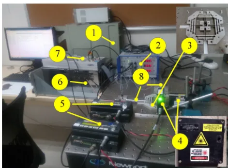
Figure 14.The experimental setup. (1) Host computer, (2) signal amplifier and controller, (3) compliant mechanism, (4) laser sen-sors, (5) laser collectors, (6) dSPACE controlling system, (7) DAQ board, (8) PZT actuators.
5.2 Optimal results
The Genetic Algorithm (GA) is adopted in the current is-sue due to its superiority of fast convergence, fewer calcu-lating time and higher robustness over other method such as simulated annealing algorithm (Mccall, 2005). The opti-mization process is implemented by the GA toolbox of the MATLAB software and the results of optimized parameters are: r=1.5 mm, t=0.78 mm, a=0.5 mm, l1=5.47 mm,
l2=14.57 mm, l3=7.90 mm, l4=27.94 mm, l5=28 mm, which will lead to an xy stage with λAR=7.87, kin= 13.39Nµm−1and the natural frequencyf =367.07 Hz.
After optimization, simulation is carried out for demon-strating performances of the optimized micromanipulation stage. Maximum input displacements are applied at x- and
y-axes and the total deflection and stress distribution of the mechanism are expressed in Fig. 13. It is observed that the output displacement of x-axis is 94.90 µm, and the corre-sponding input force is 214.63N. Therefore, the optimized mechanism has an amplification ratio of 4.75 with an in-put stiffness of 10.63Nµm−1. In addition, maximal stress is 263.68 MPa, which is far less than the yield strength of the material.
Furthermore, the first four natural frequencies are also analyzed and their values are 174.26, 348.31, 350.14 and 850.65 Hz, respectively. They are all less than the frequencies before optimizing and the frequencies ofx- andy-directions are very close to the calculated values, which demonstrate that the structure optimization is effective.
positioning stage is shown in Fig. 14. Two PZTs with stroke of 90 µm (model P-840.60 produced by Physik Instrumente, Inc.) are adopted to drive the micromanipu-lation stage, and the PZTs are actuated with a voltage of 0–100 V through a three-axis piezo-amplifier and driver (E-509 from the PI). Two laser displacement sensors and collectors (Microtrak II, head model: LTC-025-02, from MTI Instrument, Inc.) are used to measure the end-effector displacements of the two axes. The analog outputs of two sensors are connected to a PCI-based data acquisition (DAQ) board (PCI-6143 with 16-bit A/D convertors, from NI Corp.) through a shielded I/O connector block (SCB-68 from NI) with noise rejections. The digital outputs of the DAQ board are read by a host computer simultaneously.
Since the sensitivity of the laser sensor is 2.0 mm/10 V and the maximum value of 16-bit digital signal corresponds to 10 V, the resolution of the displacement detecting system can be calculated as
2.0 mm 10 V ×
10 V
216 =0.031 µm (46)
However, due to a considerable level of the noise, the reso-lution of the sensor is claimed±0.2 µm by the manufacturer. In the process of practical precision motion control experi-ments, it is found that the limitation of the fabricated proto-type mainly arises from the laser displacement sensors which have a not-high resolution of±0.2 µm.
6.2 Open test
To describe the dynamic properties of the proposed mech-anism, the corresponding open-loop tests are carried out by using the dSPACE real-time simulation control system. As shown in Fig. 15a and b, which demonstrate respectively the output displacements and parasitic motions ofx- andy -directions when the input voltage isu=30 sin(π4t−π
2)+30.
The results indicate that the actual amplification ratio of the mechanical amplifier inx-direction by comparing the input and output displacements is about 3.51 and the parasitic mo-tion for the y-direction is about 0.32 µm. While one of y -direction is calculated as 3.43 and the parasitic motion for thex-direction is only 0.31 µm. Based on the aforementioned tests, the experimental results are less than the analytical re-sults. The main reasons may come from the assembly errors of the system and the preloaded force of the PZT. Addition-ally, parasitic motions of thex- andy-axes are very small, which can be ignored. Therefore, testing results demonstrate that the designed mechanism has excellent decoupled perfor-mance.
-(a) (b)
Figure 15.The output displacements and parasitic motions:(a)the output displacement ofx-axis and parasitic motion ofy-axis;(b)the
output displacement ofy-axis and parasitic motion ofx-axis.
Figure 16.The output displacements ofx- andy-axes.
axes are shown in Fig. 16 when the two PZTs at x- and y -directions are driven simultaneously. The results indicate that the output displacements ofx- andy-directions are not iden-tical. The errors may be created by the preloaded force of PZTs and manufacturing defects between two axes.
6.3 Tracking experiments
For further validating the performances of micro/nano-positioning platform, a robust tracking controller is used to obtain the well tracking effect. The reference input dis-placement is the signal with different frequencies since the hysteresis phenomenon of piezoelectric actuator is a rate-dependent hysteresis. Therefore, the robust controller can ef-fectively eliminate the drawback caused by rate-dependent of
Table 4.Property comparisons for proposedxystages.
Refs. Frequency Cross-coupling Workspace (Hz) (%) (µm2)
Ref. 3 2.7k / 25×25 Ref. 5 831 2 119.7×121.4 Ref. 9 720.52 5 19.2×18.8 Ref. 11 2k 0.2 15×15 Ref. 12 665.4 2 8×8 This study 348.31 0.1 169.6×165.3
the PZT-actuated micromanipulator. The tracking results and corresponding errors is shown in Fig. 17, where output dis-placement is well tracking with the input disdis-placement and the error is low than 0.01 %. Thus the optimal design is suit-able for this compliant mechanism.
6.4 Discussions
From the Figs. 15 and 16, we can see that the output displace-ments of thex- andy-axes are not exactly same, the main reasons maybe come from the errors coming from installa-tion and manufacturing. Thus, the rotainstalla-tion of end-effector can exist, but it may be minor affections for the other ori-entation.
seri-(a) (b)
Figure 17.The tracking result and error:(a)the tracking result;(b)the tracking error.
ously limit their further applications. Additionally, the per-formances in terms of cross coupling and workspace of the other two stages presented in Ref. 5, Ref. 9 and Ref. 12 are obviously lower than the proposed in this study.
7 Conclusions
In this paper, a novel fully decoupled xy micro-positioning stage with lever amplifier has been proposed. The designing process of the stage is provided in consideration of the de-coupled property of the output motions. In addition, the an-alytical method and Lagrange’s method are adopted for the kinematics and dynamics modeling of the mechanism with amplification ratio, stiffness, reachable workspace and nat-ural frequency. The modeling verification and performance evaluation are carried out by FEA. Considering the perfor-mance requirement, a series of structural optimizations by using GA method have been implemented to improve the amplification ratio. Finally, prototype fabrication and ex-perimental tests are implemented in detail. All results indi-cate that the maximal cross coupling of the 2-DOF micro-positioning stage is less than 0.1 % under the workspace for 169.6 µm×165.3 µm with the natural frequency of 348.31.
For further study, intelligent controller is going to be con-sidered to control the micro-positioning stage and precise po-sition tracking will be carried out in our future work.
Data availability. This experimental data can be downloaded at
https://pan.baidu.com/disk/home?errno=0&errmsg=Auth Login Sucess&&bduss=&ssnerror=0&traceid=#/all?path=/&vmode=list (last access: 20 November 2018).
Author contributions. The main contribution for ZW includes
the structural design, modeling analysis and the control. The contri-bution for co-author MH includes the structural optimization. And the contribution for co-author YL includes the structural design and the English writing error and grammar modification.
Competing interests. The authors declare that they have no
con-flict of interest.
Acknowledgements. This work was supported in part by
Sci-ence and technology research project of department of education, Jiangxi, China (GJJ170568), National Natural Science Foundation of China (51575544, 51275353), Research Committee of The Hong Kong Polytechnic University (1-ZE97, G-YZ1G).
Edited by: Xichun Luo
Reviewed by: Calin-Octavian Miclosina and one anonymous referee
References
Choi, S. B., Han, S. S., Han, Y. M., and Thompson, B. S.: A magnifi-cation device for precision mechanisms featuring piezoactuators and flexure hinges: design and experimental validation, Mech. Mach. Theory, 42, 1184–1198, 2007.
Dong, J. D., Mukhopadhyay, D., and Ferreira, P. M.: Design, fabri-cation and testing of a silicon-on-insulator (SOI) MEMS parallel kinematicsXY stage, J. Micromech. Microeng., 17, 1154–1161, 2007.
Dong, Y., Gao, F., and Yue, Y.: Modeling and experimental study of a novel 3-RPR parallel micro-manipulator, Robot. Cim.-Int. Manuf., 37, 115–126, 2016.
Koseki, Y., Tanikawa, T., Koyachi, N., and Arai, T.: Kinematic anal-ysis of a translational 3-d.o.f. micro-parallel mechanism using the matrix method, Adv. Robotics, 16, 95–105, 2002.
Li, Y. M. and Wu, Z. G.: Design, analysis and simulation of a novel 3-DOF translational micromanipulator based on the PRB model, Mech. Mach. Theory, 100, 235–258, 2016.
Li, Y. M., Huang, J. M., and Tang, H.: A compliant parallel XY
micromotion stage with complete kinematic decoupling, IEEE T. Automat. Sci. Eng., 9, 538–553, 2012.
Li, Y. M., Wu, Z. G., and Zhao, X. H.: Optimal design and control strategy of a novel 2-DOF micromanipulator, Int. J. Adv. Robot. Syst., 10, 1–13, 2013.
Lin, C. J. and Lin, P. T.: Particle swarm optimization based feedfor-ward controller for aXY PZT positioning stage, Mechatronics, 22, 614–628, 2012.
Liu, P., Yan, P., Zhang, Z., and Leng, T.: Modeling and control of a novelX−Yparallelpiezoelectric-actuator driven nanopositioner, ISA T., 56, 145–154, 2015.
Mccall, J.: Genetic algorithms for modelling and optimisation, J. Comput. Appl. Math., 184, 205–222, 2005.
Polit, S. and Dong, J.: Development of a high-bandwidth XY
nanopositioning stage for high-rate micro-/nanomanufacturing, IEEE/ASME Transactions on Mechatronics, 16, 724–733, 2011. Qin, Y., Shirinzadeh, B., Tian, Y., and Zhang, D.: Design issues in a decoupledXY stage: Static and dynamics modeling, hystere-sis compensation, and tracking control, Sensor. Actuat. A-Phys., 194, 95–105, 2013.
Smith, S. T.: Flexures: elements of elastic mechanisms, Gordon and Breach, New York, 2000.
Su, X. P. and Yang, H. S.: Design of compliant microleverage mech-anisms, Sensor. Actuat. A-Phys., 87, 146–156, 2001a.
nanopositioning system driven by dual mode, IEEE Transation on Robotics, 29, 650–662, 2013.
Tang, H. and Li, Y. M.: Development and active disturbance rejec-tion control of a compliant micro/nano-posirejec-tioning piezo-Stage with dua-mode, IEEE T. Ind. Electron., 61, 1475–1492, 2014. Tang, H. and Li, Y. M.: A new flexure-basedY θ nanomanipulator
with nanometer-scale resolution and millimeter-scale workspace, IEEE/ASME Transation on Mechatronics, 20, 1320–1330, 2015. Tian, Y., Shirinzadeh, B., and Zhang, D.: A flexure-based mecha-nism and control methodology for ultra-precision turning opera-tion, Precis. Eng., 33, 160–166, 2009.
Wang, F., Li, J., Liu, S., Zhao, X., Zhang, D., and Tian, Y.: An Improved Adaptive Genetic Algorithm for Image Segmenta-tion and Vision Alignment Used in Microelectronic Bonding, IEEE/ASME Transation on Mechatronics, 19, 916–923, 2014. Wu, Z. G. and Li, Y. M.: Optimal design and control strategy of a
novel 2-DOF micromanipulator, Int. J. Adv. Robotic Syst., 10, 1–13, 2014.
Yong, Y. K., Aphale, S. S., and Moheimani, S. O.: Design, Iden-tification, and Control of a Flexure-BasedXY Stage for Fast Nanoscale Positioning, IEEE Transation on Nanotechnology, 8, 46–54, 2009.
Yu, J., Xie, Y., Li, Z., and Hao, G.: Design and Experimen-tal Testing of an Improved Large-range DecoupledXY Com-pliant Parallel Micromanipulator, J. Mech. Robot., 7, 044503, https://doi.org/10.1115/1.4030467, 2015.