RESEARCH ARTICLE
Hardware-in-the-loop simulation
of massive-payload manipulation on orbit
Jaesung Yang
1*, Atsushi Konno
1, Satoko Abiko
2and Masaru Uchiyama
3Abstract
This paper describes a hardware-in-the-loop simulation of massive-payload manipulation on orbit using a master– slave teleoperation system. The main problems in teleoperating a space robot arm from the earth to manipulate a massive payload are communication delay, unexpected excessive force generated between the slave arm and the payload, and geometric/dynamic modeling error. In order to overcome those problems, a teleoperation system using mixed force and motion commands is discussed. The teleoperation system is verified by performing hardware-in-the-loop simulations.
Keywords: Teleoperation, Hardware-in-the-loop simulation, Virtual environment, Massive object
© The Author(s) 2018. This article is distributed under the terms of the Creative Commons Attribution 4.0 International License (http://creat iveco mmons .org/licen ses/by/4.0/), which permits unrestricted use, distribution, and reproduction in any medium, provided you give appropriate credit to the original author(s) and the source, provide a link to the Creative Commons license, and indicate if changes were made.
Introduction
Space robotic manipulators such as SRMS (Shuttle Remote Manipulation System) and SSRMS (Space Sta-tion Remote Manipulator System) have played a vital role in satellite orbit injection and construction of the ISS (International Space Station). These space robots have been operated by astronauts on-site.
However, if such manipulation can be performed by teleoperating the space robot from the earth, there is no need to send astronauts to space, which is attractive from both safety and financial consideration.
In general, satellites or modules of space structures have huge mass compared to the robot arm. Astronauts must be very careful when operating the robot arm not to generate excessive force between the end effector of the robot arm and the massive payload being manipulated, especially when starting and stopping the movement. The main problems in the manipulation of a massive payload by teleoperating the robot arm from the earth will be communication delay and the unexpected excessive force generated between the space robot and the payload.
It is well known that a communication delay between a master arm and a slave arm greatly reduces the
performance of the teleoperation [1]. In general teleoper-ation (e.g. [2]) in which the master and the slave arms are directly coupled, an operator must take “move and wait” strategy, in which the operator must wait the delayed information of the slave-arm to confirm at every slight operation if the communication delay is large. Semi-autonomy is a solution for efficient teleoperation under communication delay [3]. Model-based teleoperation via a virtual environment has also been enthusiastically studied [4–6]. However, in model-based teleoperation via a virtual environment, an unexpected excessive force could be generated by a modeling error in the geometric or dynamic properties of the slave arm and the payload.
In order to overcome the problem of modeling error in the teleoperation, the use of mixed force and motion commands has been proposed [6, 7]. However, model-based teleoperation assumes that the master and the slave arm have similar sizes, and therefore this teleop-eration system cannot be directly applied to massive-payload manipulation. In [8], a small size master-arm was used to operate the ETS-VII manipulator, which was an actual space robot. However, only the contact force was fed-back to the operator, and hence force scaling was not considered. The power scaling was considered in [2], however the method proposed in [2] has the problem of inefficiency in teleoperation if the communication delay is large, as discussed above. In this work, model-based teleoperation is modified considering the difference in
Open Access
*Correspondence: [email protected]
1 Graduate School of Information Science and Technology, Hokkaido University, Kita 14 Nishi 9, Kita-ku, Sapporo, Japan
size between the master and the slave arms for applica-tion to massive-payload manipulaapplica-tion.
Furthermore, the modified model-based teleopera-tion is verified using a hardware-in-the-loop simula-tion (HILS). Various HIL simulators for space robots were surveyed in [9]. HIL simulators for space robots have been developed mainly to simulate the capture of space targets such as satellites [10–12]. However most HIL simulators for space robots have used conventional serial robots to reproduce the movement of the space target. Serial robots do not generally move very quickly, and hence the response delay is relatively large. The large response delay of the motion table (the robot arm used to reproduce the movement of the space target) may cause instability in HILS [13]. Hence, this work uses a parallel-robot-based HIL simulator [14], applying delay time compensation [13] in order to validate the model-based teleoperation by simulating massive-payload manipulation.
The main contributions of this paper are the proposal for a modified version of model-based teleoperation using mixed force and motion commands and the paral-lel-robot-based HILS of the massive payload manipula-tion. The proposed method deals with force scaling. In force scaling, mitigation of excessive force at the remote site will be the key issue, because the operator’s com-mands are scaled-up at the remote site, and there is a serious communication delay. The mitigation of gener-ated force at the remote site using the proposed method was verified by performing HIL simulations.
Hardware‑in‑the‑loop (HIL) space robot simulator
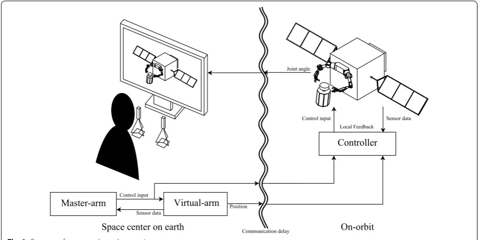
The concept of a space robot teleoperation system is illustrated in Fig. 1. In the space center on earth, an operator manipulates the master arms by looking at the virtual environment and predicting the movement of the space robot on orbit. The control inputs from the master arms and the position data of the virtual arm are transferred to the slave arm on orbit with a com-munication delay. The slave arms on orbit follow the motion commands generated by the master arms on earth. When the slave arms contact with the payload or the environment, the contact force is locally controlled using force sensor data. However, the slave arms’ posi-tion data arrive at the space center on earth with a communication delay. Hence, the positions of the slave arms at the moment of teleoperation are unknown on earth. In order to overcome the communication delay problem, simulated motions of the slave arms (virtual arms) are displayed for the human operator. The simu-lated motion is transferred to the slave arm controller as well as the motion command generated by the mas-ter arms (see Fig. 1). The motion of the virtual arms modifies the slave arm’s position in order to eliminate the error between the slave arm and virtual arm. The joint angle data of the slave arm are transferred to the virtual environment in order to display the movement of the slave arm, which is superimposed on the move-ment of the virtual arm. The system can be divided into the hybrid motion simulator, the slave system, and the master system.
Master-arm
Controller
Virtual-arm
Local Feedback
Sensor data Control input
Control input
Sensor data Position
On-orbit Space center on earth Communication delay
Joint angle
HIL simulator
The HIL simulator [14] is composed of a 6 axis force sen-sor for acquiring the external force, an X-Y motion table for reproducing the translational large movement of the payload, and a HEXA-type [15] motion table for repro-ducing 6-DOF guide movement. The force sensor is mounted at the boundary of the hardware simulation and software simulation. In the HIL simulation, a force and torque acting on the payload are measured by the force/ torque (F/T) sensor. The relative position and orienta-tion with respect to the payload of interest are calculated by solving a dynamic equation with the measured force/ torque data. Finally, the calculated relative position and orientation are realized on the hardware side by a servo-mechanism in real time (see Fig. 2). The response delay time compensation method [13] is applied to the hybrid simulator.
Slave system
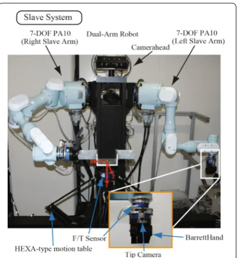
The slave system is composed of two 7-DOF manipula-tors with a serial link mechanism and a camera head system for monitoring the working environment (see Fig. 3). The camera head can pan and tilt to see the workspace. A wrist camera, a 6-axis force sensor and a BarrettHand™ (Barrett Technology, LLC) for grasping the various payloads are mounted on each end effec-tor. The 6-axis force sensor acquires the force generated at the wrist of the slave arm. The BarrettHand is able to
open and close fingers to grip a payload. The end effector camera is used to obtain detailed information with a dif-ferent field of view angle of the camera head.
Simulation Objects (Numerical Models)
Physical Models
Physical Space F/T Sensor Numerical Space
Pick Up a Part of Numerical Models as Physical Models
Fig. 2 Concept of the hybrid simulation
Master system
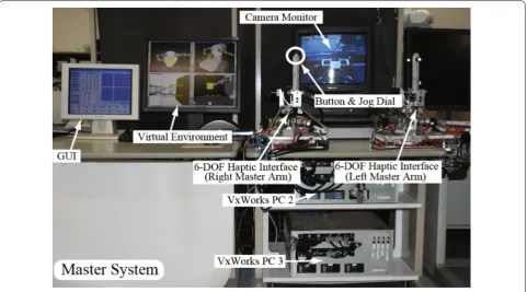
The master system (see Fig. 4) is composed of two 6-DOF haptic interfaces with a parallel link mechanism [16]. The force sensor used in the 6-DOF haptic interface is NANO 5/4-A (Bl Autotec). The 6-DOF haptic interface is used in the joystick mode (the haptic device does not move and does not display forces in the joystick mode) in this work. The virtual environment is displayed on a monitor.
Development of virtual environment and control law
Operation scenario
The assumed task is to convey a massive payload by tel-eoperating a space robot. A grip mounted on the HEXA-type motion table (Fig. 3) is assumed to be a part of the massive payload. The force applied to the grip is meas-ured by an F/T sensor mounted between the grip and the HEXA-type motion table. The measured force and torque are considered to be the external force applied to the virtual massive payload. The motion of the mas-sive payload is calculated by solving a dynamic equation, and the motion is reproduced by the HEXA-type motion table mounted on the X-Y table.
In the operation scenario, it is assumed that a human operator on earth teleoperates a space robot arm (slave arm) to manipulate a massive payload.
Control law
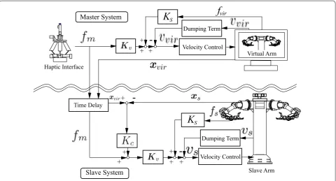
In this work, the haptic device shown in Fig. 4 is used as a master arm in the joystick mode. The force applied by the human operator to the stylus of the master arm is meas-ured by an F/T sensor and is transformed into a velocity command of the slave arm. A block diagram of the tel-eoperation system is illustrated in Fig. 5.
Let xi = [rTi φTi ]T and vi= [r˙Ti ωTi ]T (i=m, vir, s, or t) be the six dimensional position and velocity vectors, respectively. Subscripts m, vir, s, and t, respectively, rep-resent the master arm, virtual arm, slave arm, and mas-sive payload. φi and ωi denote a set of three variables for
orientation (e.g., Euler angles) and the angular velocity vector, respectively. The derivative of xi is transformed
into vi by the matrix B(φi) as vi=B(φi)x˙i.
In the teleoperation with a communication delay, both geometric and dynamic modeling errors are serious problems. If there are very large discrepancies between the real environments at the remote site and their mod-els, it may not be possible to catch/contact a payload with the slave arm via teleoperation, because the operator on earth would not be able to monitor the remote site in real time. Large discrepancies between the dynamic prop-erties of the slave arm/payload and those of the models may cause an unexpected excessive force to be gener-ated between the slave arm and the payload. In order to overcome those problems, model-based teleoperation
using mixed force and motion commands has been pro-posed [6, 7].
This work uses model-based teleoperation [6, 7], but it is modified to apply to massive payload manipulation. The main modification pertains to the scaling between the master arm and the slave arm. The original model-based teleoperation using mixed force and motion com-mands [6, 7] assumed that the force and motion in both arms (master and slave arms) were of the same scale. However, in massive-payload manipulation, the force/ motion command given by a human operator should be scaled up so that the large-sized slave arm can manipu-late the massive payload. In the following sections, modi-fied model-based teleoperation using mixed force and motion commands is presented.
Control law of slave arm
The velocity command to the slave arm, vs,c(t) , is given as
follows:
where fm is the reference force commanded by the
human operator using the master arm, fs is the actual
(1)
vs,r(t)=KsGfm(t),
(2)
vs,c(t)=vs,r(t−tdelay)−Ksfs(t) +KcB(xvir(t−tdelay)−xs(t))
− D(vs(t−�t)−vs(t−2�t)),
force generated at the slave arm, G is a diagonal scaling matrix between the force commanded by the master arm and the force the slave arm is expected to generate. In order for the slave arm to manipulate the massive pay-load, the force command fm given by the human
oper-ator must be scaled up for the slave arm. The matrix G scales up the reference force. Substituting (1) into (2), the following equation is obtained:
vs,r is the reference velocity given by (1). xvir is the
position vector of the slave arm. They are transferred from the earth and arrive at the space robot tdelay later.
Hence, fm and xvir used in (3) are tdelay ahead of the
local (space) time. xs is the position vector of the slave
arm, Kc is a gain matrix for the restraint force, fs is a
force vector measured by the F/T sensor of the slave arm, and Ks is a diagonal force feedback gain matrix. D
is a diagonal damping gain matrix. t is the sampling
period of the controller. The original model-based tel-eoperation using mixed force and motion commands [6, 7] was not always stable in HILS, and hence the damp-ing term (the last term of the right hand side of 2) is added in this work.
(3) vs,c(t)=Ks(Gfm(t−tdelay)−fs(t))
+KcB(xvir(t−tdelay)−xs(t))
− D(vs(t−�t)−vs(t−2�t)),
Master System
Virtual Arm
Haptic Interface
Slave System
Velocity Control
Time Delay
Velocity Control
Slave Arm
+
+
-++
Dumping Term
Dumping Term
-+
fvir
K
SK
S+
-+ + +
Virtual arm
Model-based virtual robots between the real robot and the master arm have been widely used to overcome communication delay (e.g., [6]), or unexpected events (e.g., [17, 18]).
In this work, the virtual arm is used to compensate for the modeling error in dynamic properties as well as to overcome the communication delay. The difference in the positions between the virtual slave arm and the real slave arm is feedback to the real slave arm control, as shown in the second term of the right-hand side of (2). The term helps reduce the positioning error caused by the modeling error in the dynamic properties of the slave arm. The reference velocity of the slave arm is also given to the virtual arm as follows:
Similar to the velocity command to the slave arm (2), the velocity command to the virtual arm is given as follows
where vvir is the velocity of the virtual arm. The matrix
B−1 transforms vvir into x˙vir . The virtual arm control law is almost the same as the control law of the slave arm to predict the movement of the slave arm and present it in the virtual environment. When the slave arm employs high-ratio reduction gears at the joints, vs can be
approxi-mated by vs,c (see Appendix A). Therefore, the velocity of
the virtual arm, vvir , is approximated by vvir,c.
In the virtual environment, the contact force between the massive payload and the end effector of the slave arm is simulated by a spring-damper system, as illustrated in Fig. 6. fvir is simulated as follows:
where Kt is a spring constant matrix, Dt is a viscosity
coefficient matrix, xt is a position vector of the virtual
massive payload, and vt is a velocity vector of the payload.
The acceleration of the massive payload is expressed by
where m is the mass, E∈R3×3 is an identity matrix, and I ∈R3×3 is the inertia tensor of the massive pay-load. The massive payload will be a satellite or a module of a space structure, and hence m and I are known (they can be obtained from the design parameter). However, (4)
vvir,r(t)=vs,r(t)=KsGfm.
(5) vvir,c(t)=vvir,r(t)−Ksfvir(t)
−D(vvir(t−�t)−vvir(t−2�t)),
(6)
xvir(t)=xvir(t−�t)+B−1vvir(t)�t,
(7) fvir(t)= −KtB(xvir(t−�t)−xt(t−�t))
−Dt(vvir(t−�t)−vt(t−�t)),
(8) ˙
vt(t)=M−1fvir(t), M=
mE 0 0 I
the inertia matrix M may include a modeling error. The
position of the payload is estimated by (8–10), hence the modeling error in M in (8) causes an estimation error.
The position error caused by the modeling error is com-pensated for by the coupling term in the slave arm con-troller (the third term of the right hand side of 2).
The velocity and position of the massive payload are calculated by
Virtual environment
As discussed in Section "Virtual arm", the velocity of the virtual arm, vvir , was approximated by vvir,c assuming high
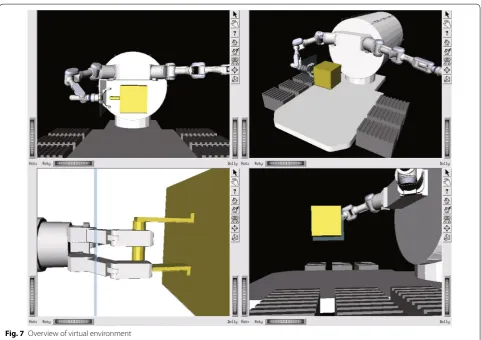
reduction gear ratios at the joints. Only the dynamics of the massive payload was considered in the virtual envi-ronment (7–10). The dynamics of the massive payload, (7–10), is used in the computation of the force feedback term of the velocity command (5). The calculation time of the virtual environment is 1 ms/loop, which is small enough compared to the video frame rate (33 ms). The virtual arm and the massive payload from the four dif-ferent viewpoints are displayed on a screen (see Fig. 7). Zooming the camera is also possible on the computer graphics. The motions of the virtual arms are displayed with a solid model. The motions of the slave arms con-structed from the joint data transferred from space are superimposed with a wire frame model on the motion of the virtual arms. This makes it easier to check whether the slave arm follows the virtual arm after a time delay.
Verification experiments
Validity of HIL simulation
HIL simulations were performed to confirm the validity of the system. In the HIL simulation, it is assumed that (9)
vt(t)=vt(t−�t)+v˙t(t)�t,
(10)
xt(t)=xt(t−�t)+B−1vt(t)�t.
x
virK
tx
tD
tM
the slave arm grips a massive payload of 3000 kg and pulls it along the x-axis at a speed of 0.01 m/s for 20 s. The mass and inertia of the virtual payload assumed in the experiment are presented in Table 1. The gains used in the experiment are shown in Table 2.
In the HIL simulation, the step input of the reference velocity of vs,r= 0.01 m/s was given instead of human
tel-eoperation. The velocity command vs,c was calculated by (2) with vs,r = 0.01 m/s. vs,r , vs,c , and vs during the HIL
simulation are plotted in Fig. 8. As it satisfies this condi-tion, the end effector velocity vs is reduced by force
feed-back and asymptotically converges to vs,r (0.01 m/s).
Figure 9 shows the force fs measured by the force sensor at the wrist of the slave arm. In order to accel-erate the massive payload of 3000 kg to a velocity of 0.01 m/s, a momentum of 30 Ns is necessary. As shown in Fig. 8, a step reference velocity vs,r = 0.01 m/s was
given at t = 176.5 s and vs almost converged to vs,r
at t = 186 s. fs plotted in Fig. 9 was integrated from 176.5 to 186 s, and the integral value was 28.43 Ns. It is assumed that the velocity of the massive payload is almost the same as the velocity of the slave arm. There-fore the movement of the massive payload in the HIL
simulation almost agrees with theory. The error in the momentum required to accelerate the massive payload from 0 to 0.01 m/s was about 5%. The force feedback term of the control law of the slave arm adequately mitigated the applied force and the velocity of the slave arm asymptotically converged to the given reference velocity.
Comparison of the results with and without force feedback
Another HIL simulation was performed to verify the effectiveness of the force feedback in (2) in reducing the resultant force during the massive-payload manipulation mission. When a virtual payload of 3000 kg is manipu-lated in a HIL simulation without force feedback, a huge force will be generated between the payload and the end Fig. 7 Overview of virtual environment
Table 1 Mass and inertia parameters of the payload
Mass [kg] Inertia [kgm2]
500 diag [7.47 7.60 7.61]
effector of the slave arm, and hence there is a risk that the slave arm used in this research will be broken. There-fore, in this HIL simulation, a massive payload of 500 kg is used instead of 3000 kg.
The massive payload of 500 kg was grasped by the slave arm and pulled automatically for 1 min at a speed of 0.01 m/s along the x-axis with and without force feed-back. Figure 10 shows the force generated between the slave arm and the payload in an automatic manipula-tion experiment for the payload of 500 kg without force
feedback. In the experiment without force feedback, a maximum force of 23 N was generated when the payload was grasped, the arm started to pull the payload, and then the arm stopped pulling, as shown in Fig. 10.
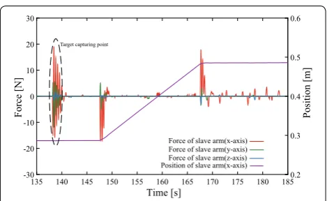
Figure 11 shows the force generated between the slave arm and the payload in an automatic manipulation experiment of 500 kg with force feedback. In the experi-ment with force feedback, a maximum force of 18 N was generated at the time when the payload was grasped, the arm started to pull the payload, and then the arm stopped pulling, as shown in Fig. 11. During the manipulation, the generated force was kept small. The mean square error of fs is calculated as follows to compare the results of the experiments with and without force feedback:
where N is the number of number of data items. MSE(fs)
was 5.41 N 2
and 15.35 N 2
when the force feedback was applied and was not applied, respectively.
Thus, it can be concluded that the force feedback in the slave arm controller helps reduce the force generated at the slave arm when the arm conveys a massive payload.
HIL simulation of massive‑payload manipulation
Scenario of experiments
Two types of HIL simulations (HILS 1 and HILS 2) were performed.
First, a virtual massive payload of 4500 kg was grasped by the slave arm and was transferred along the x-axis at a constant speed of 0.01 m/s for 20 s (HILS 1). Next, a virtual massive payload of 4500 kg was grasped by the slave arm and was transferred along the x-axis by human teleoperation with a communication delay of 5 s (HILS 2) (see Additional file 1). In the teleoperation experiment, the input values for the y and z axes components are assumed to be zero.
The effectiveness of the model-based teleoperation using the mixed force and motion commands for the problem of communication delay was verified in [6] by performing a teleoperation experiment between Ger-man Aerospace Center (DLR, GerGer-many) and Tohoku University (Japan). In this work, the effectiveness of the modified version of the model-based teleoperation for massive-payload manipulation is verified.
Although the same HILSs were carried out with vir-tual payloads of 3000 kg and of 6000 kg, only the result with the virtual payload of 4500 kg is presented in this paper. The mass and inertia used in the HILS are shown in Table 3. The gain parameters of the experiment were (11) MSE(fs)= 1
N ∞
t=0 �fs�2,
Table 2 Gain parameters of the experiment
Kv diag [80/1000 80/1000 80/1000 0 0 0]
Ks diag [1/1400 1/1400 1/1400 0 0 0]
D diag [0.3 0.3 0.3 0 0 0]
Kt diag [746,000 746000 746,000 0 0 0]
Dt diag [1000 1000 1000 0 0 0]
176 177 178 179 180 181 182 183 184 185 186 −4
−2 0 2 4 6 8 10 12 x 10−3
Time [s]
Reference Velocity [m/s
]
Reference Velocity Velocity Command Velocity
Fig. 8 Comparison between vs,c and vs,r (x-axis)
176 178 180 182 184 186 −20
−15 −10 −5 0
Time [s]
Force [N
]
the same as the parameters used in the experiments presented in “Verification experiments” section.
Comparison between the end effector force of the slave arm and the end effector force of the virtual arm (HILS 1)
In order to evaluate the accuracy of the simple virtual force model illustrated in Fig. 6, the end effector force of the slave arm generated along the x-axis is compared with that of the virtual arm as shown in Fig. 12.
Although the oscillation of the force was not repro-duced by the simple spring-damper model, the model reproduced the mean value of the force with sufficient accuracy. It can be concluded that the dynamics of the massive payload of the slave side was modeled well by the simple spring-damper virtual force model.
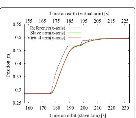
Comparison between the end effector position of the slave arm and the end effector position of the virtual arm (HILS 1)
The positions of the end effectors of the slave and virtual arm along the x-axis are plotted in Fig. 13. Because the positions of both arms along the y and z axes were almost constant and identical, only the positions along the x-axis are presented.
Because the position of the virtual arm was sent to the slave arm, and it was used in the slave arm control (the third term of the right hand side of 2), the motion of the virtual arm almost corresponds to the motion of the slave arm (note that the time delay was zero in HILS 1).
Comparison between the end effector force of the slave arm and the end effector force of the virtual arm (HILS 2)
Figure 14 shows the end effector force along the x, y, and z axes of the slave arm and the end effector position along the x-axis of the slave arm, respectively, when a virtual massive payload of 4500 kg was transferred by human tel-eoperation with a time delay (HILS 2). Figure 15 shows the reference velocity of the slave arm given by human teleoperation (see 4).
In HILS 2, the maximum end effector force was approximately 28 N. Compared to the result in HILS 1, the maximum end effector force generated in HILS 2 was larger, because the end effector reference velocity vs,r
generated by human teleoperation tends to be larger than the constant reference velocity vs,r = 0.01 m/s given in
HILS 1 (see Fig. 15).
Figure 16 shows the forces generated at the slave and virtual arms. Note that the time axis on earth (for the vir-tual arm) is shifted 5 s later for the time axis on orbit (for the slave arm) in Figs. 16 and 17 in order to compare the results of the slave and virtual arms.
Time [s]
140 145 150 155 160 165 170 175 180 185 190 195
Force [N ] -30 -20 -10 0 10 20 30 Position [m ] 0.2 0.3 0.4 0.5 0.6
Force of slave arm(x-axis) Force of slave arm(y-axis) Force of slave arm(z-axis) Position of slave arm(x-axis) Target capturing point
Fig. 10 Force and position of slave arm without force feedback
Time [s]
135 140 145 150 155 160 165 170 175 180 185
Force [N ] -30 -20 -10 0 10 20 30 Position [m ] 0.2 0.3 0.4 0.5 0.6
Position of slave arm(x-axis) Force of slave arm(x-axis) Force of slave arm(y-axis) Force of slave arm(z-axis) Target capturing point
Fig. 11 Force and position of slave arm with force feedback
Table 3 Mass and inertia parameters of the payload (4500 kg)
Mass [kg] Inertia [kgm2]
4500 diag [67.22 68.42 68.46]
Time [s]
155 160 165 170 175 180 185 190
Force [N ] -20 -15 -10 -5 0 5 10 15 20 25 Position [m ] 0.1 0.2 0.3 0.4 0.5 0.6 0.7
Position of slave arm(x-axis) Force of slave arm(x-axis) Force of virtual arm(x-axis)
As shown in Fig. 16, the force generated at the virtual arm simulates the force of the slave arm well, although a small oscillation of the force was not reproduced.
Comparison between the end effector position of the slave arm and the end effector position of the virtual arm (HILS 2)
Figure 17 shows the positions of the end effectors of the slave and virtual arms. The maximum error between the positions of the arms was 0.002 m, which was slightly larger than the errors in HILS 1.
Thus, it is proved that the motion of the virtual arm predicts the motion of the slave arm well, and hence the 0.25
0.3 0.35 0.4 0.45 0.5 0.55
155 160 165 170 175 180 185 190
Position [m
]
Time [s]
Reference(x-axis) Slave arm(x-axis) Virtual arm(x-axis)
Fig. 13 Position of slave arm and virtual arm (x-axis) (in HILS 1)
-30 -20 -10 0 10 20
160 170 180 190 200 210 220 230 0.1 0.2 0.3 0.4 0.5 0.6 0.7
Force [N
]
Position [m
]
Time [s]
Force of slave arm(x-axis) Force of slave arm(y-axis) Force of slave arm(z-axis) Position of slave arm(x-axis)
Fig. 14 Force of slave arm and position of slave arm (x-axis) (in HILS 2)
0 0.005 0.01 0.015 0.02 0.025 0.03
160 170 180 190 200 210 220 230
Velocity [m/s
]
Time [s]
Fig. 15 Reference velocity of slave arm (x-axis) (in HILS 2)
-30 -20 -10 0 10 20
160 170 180 190 200 210 220 230
Force [N
]
Time on orbit (slave arm) [s] Force of virtual arm(x-axis)
Force of slave arm(x-axis) 155 165 175 185 195 205 215 225
Time on earth (virtual arm) [s]
Fig. 16 Force of slave arm and virtual arm (x-axis) (in HILS 2)
0.25 0.3 0.35 0.4 0.45 0.5 0.55
160 170 180 190 200 210 220 230
Position [m
]
Time on orbit (slave arm) [s] Reference(x-axis)
Slave arm(x-axis) Virtual arm(x-axis)
155 165 175 185 195 205 215 225 Time on earth (virtual arm) [s]
proposed method is effective for the massive-payload manipulation task by teleoperation with time delay.
Conclusion
In this paper, a teleoperation system for a massive pay-load transportation task was proposed. The proposed control strategy was verified by performing hardware-in-the-loop simulations (HILSs).
It is confirmed that the control law to reduce the force generated between the slave arm and the massive payload works well. Furthermore, a virtual arm control law to reproduce the dynamics of massive payloads in a virtual environment is proposed. Several HILSs were carried out to verify the proposed system, and the differences between the results with and without the force feed-back term were compared. It was verified that the mas-sive-payload manipulation task can be performed while reducing the force generated between the end effector and the massive payload. HILSs of massive payload trans-port were also performed under a time delay environ-ment, and it was verified that the movements and forces on the slave side were well reproduced in the virtual envi-ronment. The modified version of the model-based tel-eoperation will be applied to more complicated tasks in future work.
Additional file
Additional file 1. This is a movie file of the massive-payload manipulation simulation experiment.
Authors’ contributions
AK led and directed the project. AK showed the need for dealing with massive payloads in teleoperation. JS proposed the control law to reduce the force generated between the end effector and the massive payload using the force sensor value of the slave arm. JS also proposed the control law of the virtual arm to reproduce the dynamics of massive payloads in the virtual environ-ment. AK participated in the discussion on the optimization of the control law. All authors read and approved the final manuscript.
Author details
1 Graduate School of Information Science and Technology, Hokkaido University, Kita 14 Nishi 9, Kita-ku, Sapporo, Japan. 2 Department of Electrical Engineering, Shibaura Institute of Technology, 3-7-5, Toyosu, Koto-ku, Tokyo, Japan. 3 Graduate School of Engineering, Tohoku University, 2-1-1 Katahira, Aoba-ku, Sendai, Japan.
Acknowledgements
The authors acknowledge Tohoku University for the experimental equipment and we are grateful Dr. Sugai for the robot programming support.
Competing interests
The authors declare that they have no competing interests.
Availability of data and materials
The datasets used and/or analysed during the current study are available from the corresponding author onreasonable request.
Funding
The authors received no specific funding for this research.
Appendix A: Dynamics of the virtual arm
If high-ratio reduction gears are employed at the joint, the joint angles and joint torques between before and after the gear reduction are related by
where Gr is a diagonal reduction matrix, the diagonal
ele-ments of which correspond to the reduction ratio; q is
the joint angle vector of an arm; qa is the angle vector of
the actuators; τ is the joint torque vector; and τa is the torque vector of the actuators.
The dynamics of the arm is expressed by
where M is the inertia matrix of the arm, h represents
the Coriolis force and centrifugal force and gravitational force, J is the Jacobian matrix, and F is the external force.
Substituting (12) and (13) into (14), the following equa-tion is obtained:
Assuming that the actuator is the velocity command type, the actuator torque is calculated as
where q˙ca is the joint angle velocity command. Kva cor-responds to the gain of the hardware velocity servo.
Substituting (16) into (15), the following equation is obtained:
By multiplying both sides of (17) by J , the following equation is obtained:
Therefore, by using vc=Jq˙c and v=Jq˙ , (18) is rewritten as
If the reduction ratio is large enough, the two terms on the right hand side of (19) can be ignored, because the first term is proportional to G−3 and the second term is (12)
Grq=qa,
(13) τ =GTrτa(∵�qTτ =�qTaτa=�qTGTr τa),
(14) τ =Mq¨+h+JTF,
(15) τa=G−rTMG
−1
r q¨a+Gr−T(h+JTF).
(16) τa=Kva(q˙ca−q˙a)
=KvaGr(q˙c−q˙)(∵q˙ca−q˙a=Gr(q˙c−q˙)),
(17) ˙
qc−q˙ =G−r1K
−1
vaG
−T r MG
−1
r q¨a+G−r1K
−1
vaG
−T
r (h+JTF).
(18) J(q˙
c−q)˙
=J G−1r K−1vaG−rTMG−1r q¨
a+J G−1r K−1vaGr−T(h+JTF).
(19) vc−v=J G−r1K−
1
vaG− T r MG−
1
r qa¨
+J G−r1K −1
vaG −T r (h+J
proportional to G−2 . In this case, v can be approximated
by vc . In massive-payload manipulation simulation, F in
the second term may become very large and hence it may not be possible to ignore the second term. However, if F
is adequately controlled by force feedback (e.g. KsFs in
2), the second term of the right hand side of (19) will be sufficiently small and the assumption v≈vc will hold.
Publisher’s Note
Springer Nature remains neutral with regard to jurisdictional claims in pub-lished maps and institutional affiliations.
Received: 12 December 2017 Accepted: 22 August 2018
References
1. Cl J, Craig RC, David LA (2001) Time delay and communication band-width limitation on telerobotic control. Int Syst Smart Manuf Int Soc Optics Photon 4195:405–419
2. Secchi C, Stramigioli S, Fantuzzi C (2008) Variable delay in scaled port-Hamiltonian telemanipulation. Mechatronics 18(7):357–363 3. Sayers CP, Richard PP, Louis LW, Dana RY (1998) Teleprogramming for
subsea teleoperation using acoustic communication. IEEE Jo Ocean Eng 23(1):60–71
4. Niemeyer G, Slotine JJE (2004) Telemanipulation with time delays. Int J Robot Res 23(9):873–890
5. Ryder CW, Sean MS, Elliot WH, David LC, Hao J, Mark RC, Allison MO (2014) Time-delayed teleoperation for interaction with moving objects in space. In: 2014 IEEE international conference on robotics and automation (ICRA) 6. Tsumaki Y, Goshozono T, Abe K, Uchiyama M, Koeppe R, Hirzinger G
(2000) Verification of an advanced space teleoperation system using internet. In: Proceedings of the 2000 IEEE/RSJ international conference on intelligent robots and systems (IROS 2000), vol. 2. pp 1167–1172
7. Tsumaki Y (1998) A model-based space teleoperation system using mixed force and motion commands. Trans JSME 64(626):3901–3906
8. Yoon WK, Goshozono T, Kawabe H, Kinami M, Tsumaki Y, Uchiyama M, Oda M, Doi T (2004) Model-based space robot teleoperation of ETS-VII manipulator. IEEE Trans Robot Autom 20(3):602–612
9. Yoshida K (1996) Experimental platforms for research and development of space robots. J Robot Soc Japan 14–1:18–21
10. Wenfu X, Bin L, Yangsheng X, Cheng L, Wenyi Q (2007) A ground experi-ment system of free-floating robot for capturing space target. J Intell Robot Syst 48(2):187–208
11. Rouleau G, Rekleitis I, L’Archeveque R, Martin E, Parsa K, Dupuis E (2006) Autonomous capture of a tumbling satellite. In: Proceedings 2006 IEEE international conference on robotics and automation (ICRA 2006) 12. Boge T, Wimmer T, Ma O, Zebenay M (2010) Epos-a robotics-based
hardware-in-the-loop simulator for simulating satellite rvd operations. In: 10th International symposium on artificial intelligence robotics and automation in space
13. Osaki K, Konno A, Uchiyama M (2010) Delay time compensation for a hybrid simulator. Adv Robot 24(8–9):1081–1098
14. Takahashi R, Ise H, Konno A, Uchiyama M, Sato D (2008) Hybrid simula-tion of a dual-arm space robot colliding with a floating object. In: 2008 IEEE international conference on robotics and automation (ICRA). pp 1201–1206
15. Uchiyama M, Iimura Ki, Pierrot F, Unno K, Toyama O (1992) Design and control of a very fast 6-dof parallel robot. In: Robotics mechatronics and manufacturing systems. pp 473–478
16. Tsumaki Y, Naruse H, Nenchev DN, Uchiyama M (1998) Design of a com-pact 6-dof haptic interface. In: Proceedings of the 1998 IEEE international conference on robotics and automation, vol. 3, pp 2580–2585
17. Kikuuwe R, Yasukouchi S, Fujimoto H, Yamamoto M (2010) Proxy-based sliding mode control: a safer extension of pid position control. IEEE Trans Robot 26(4):670–683