Power Distribution and BER in Indoor VLC with PPM
Based Modulation Schemes: A Comparative Study
Suzan M. El-Garhy1, Heba Fayed 1 and Moustafa Aly 1,2,*1 Arab Academy for Science, Technology and Maritime Transport, Alexandria 1029, Egypt; [email protected]; [email protected]; [email protected]
2 OSA member
* Correspondence: [email protected]; Tel.: +2-0100-663-9473
Abstract: Visible Light Communication (VLC) uses an intensity-modulation and direct-detection (IM/DD) scheme to transmit data. The light source utilized in VLC structures is constantly switched on and off rapidly, resulting in flickering. Furthermore, most of illumination systems exclude dimming support to permit customers to dim the light source to the desired stage. Therefore, the modulation scheme for information transmission in VLC should consist of flicker mitigation and dimming manage abilities. Double inverse pulse position modulation (DIPPM), sub-carrier pulse position modulation (SC-L-PPM), and M-ary variable pulse position modulation (M-VPPM) are recommended for minimizing the flicker issues and supporting an excessive degree of dimming for VLC systems. In this paper, a comparison is introduced between DIPPM, SC-L-PPM, and M-VPPM according to error performance and bit rate. In addition, a simulation is carried out to measure the optical power distribution for a LED lamp in an indoor room topology for each modulation technique. The obtained results indicated that SC-L-PPM is the best choice regarding the bit error rate (BER) and optical power distribution compared to the other two schemes. A 10-6 BER is achieved
with a very low power requirement at L=8, while a remarkable power distribution of 1.5 to 6.5 dBm is observed from 3×5×5 m3 room corners to the center, respectively. According to the bit rate, it is
noticed that, M-VPPM is the most efficient one compared to the two other schemes. It achieves 2.3×10⁷ bps at signal to noise ratio (SNR) of 22 dB and M=8.
Keywords: VLC; DIPPM; SC-L-PPM; M-VPPM; BER; Bit Rate; Power Distribution.
1. Introduction
T
he spectral limitation of Radio Frequency (RF) restricts the demand of increasing capacity. Moreover, RF suffers from several drawbacks like: 1) electromagnetic interference, 2) RF waves penetrate the wall causing a security problem, and 3) increasing transmitted power leads to harm human health. In order to conquer the disadvantages of RF technology, a visible light communication (VLC) is one of the optimum solutions. The VLC spectral range varies between 380 nm to 750 nm equivalent to frequency spectrum 430 THz to 790 THz which overcomes the limited bandwidth in RF. It is more secure as the light does not penetrate the walls. Non-Licensed Channel is the most important feature of the VLC technology [1].VLC using white LED is more beneficial than incandescent for many reasons as: a) its long life time, b) minimum generated heat, c) low power consumption, d) high brightness, e) reliability f) small in size, g) fast switching [2]. Owing to these benefits of white LED, it is recommended to be the source of future application (indoor and outdoor) for both lighting and data transmission as well.
The several features of VLC make it attractive for practical use. There are many different practical applications such as vehicle to vehicle communication, underwater communication,
hospitals, information display signboard, visible light ID symbol, and sound communication system [1].
The two main obstacles for VLC physical layer are flicker and dimming control [3]. Controlling the dimming level is achieved using different modulation techniques. Therefore, the design of a modulation technique requires meticulous care to avoid these obstacles during communication.
This paper deals with several types of single carrier modulation (SCM) techniques that are used in VLC. The variable pulse position modulation (VPPM) is one of the SCM techniques that are standard by IEEE 802.15.7 [4]. A VPPM uses pulse position modulation (PPM) for modulating the message and pulse width modulation (PWM) to adapt the dimming level [5]. It has a high ability to control the diming, but it suffers from a limited bit rate. M-ary VPPM is introduced to overcome the low bit rate of VPPM [6]. However, the double inverse pulse position modulation (DIPPM) is more power efficient than VPPM, and the subcarrier pulse position modulation (SC-PPM) is the most power efficient VLC modulation technique with acceptable bitrate [7, 8].
In this paper, a comparative study between DIPPM, SC-L-PPM and M-VPPM schemes is performed addressing power distribution, bit rate and BER performance. A parametric study is applied in each scheme to extract the best performance conditions. A nomination regarding each performance is achieved.
This paper is organized as follows. Section 2 introduces the mathematical background. The obtained results are presented and discussed in Sec. 3. Section 4 is devoted for the main conclusions.
2. Mathematical Background
2.1 Scheme Structure and BER/Bit Rate
In this section, a symbol structure for each scheme is explained. Moreover, a bit error rate formula is introduced.
A. Double inverse pulse position modulation (DIPPM)
The DIPPM can be obtained by applying a modification on inverse pulse position modulation (L-IPPM). In inverse pulse position modulation (L-IPPM), the symbol duration, Ts, is divided into L
time slots. One slot is off while the others are on. The position of the off slot can be used to distinguish the transmitted information. The number of bits transmitted in the symbol is n = log L [8].
In DIPPM, the reduced L-IPPM symbol of duration Ts/L2 is inserted in the off slot of the IPPM
symbol to generate a DIPPM symbol. The symbol structure of 2-DIPPM symbol is illustrated in Fig.1 [9]. The DIPPM dimming can be controlled by changing the instantaneous power of light source.
(b)
Figure 1. Symbol structure of 2-DIPPM symbol (a) Bit 0 symbol and (b) Bit 1 symbol [9].
To initialize the comparison study, the relation between bit error rate (BER) versus power at different dimming ratios can be obtained using [9].
𝐵𝐸𝑅 = 𝑄 (1)
where d is the dimming ratio, R is the bit rate , N is the power spectral density, and P is the power
received.
B. Subcarrier pulse position modulation (SC-LPPM)
The SC-LPPM has two components called subcarrier component and DC component. The symbol duration, Ts, of the SC-LPPM scheme is divided into L time slots of duration T/L. The optical
transmitted signal is the subcarrier in one slot while the other has the same amplitude. The position of the subcarrier signal is equal to the decimal value of the corresponding symbol. Figure 2 shows an example of SC-LPPM wave form when L = 4.
Figure 2. SC- 4PPM wave form for L = 4.
In SC-L-PPM, the receiver and the transmitter must be synchronized at the same slot and symbol to demodulate the signal at the receiver [7].
The bit error rate of SC-LPPM can be obtained as [10]
𝐵𝐸𝑅 = / 𝑄 (2)
where Aeff is the receiver effective area and P is the power received at photodiode (PD).
C. M-ary variable pulse position modulation (M-VPPM)
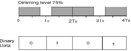
Figure 3. Operating example of VPPM at dimming 75%.
The VPPM scheme is simple and easy to implement. On the other hand, its bit rate is limited because it uses a binary PPM scheme. To overcome this limitation, M-VPPM is utilized to enhance the achievable bit rate performance [6].
The BER of M-ary VPPM is given by
𝐵𝐸𝑅 = erfc γ ( ) (3)
where 𝛼 is the largest non-diagonal value of the correlation factor matrix, and 𝛾 is defined as
the scaling coefficient that contains the effects of the channel path loss gain and photodiode responsivity.
The bit rate, Rb, of M-VPPM can be obtained from
Rb = (1 – BER). (log2 M)/Ts (4)
where M is the modulation order and Ts is the symbol duration.
2.2 Optical Power Distribution
The optical power transmitted represents the energy irradiated from the LED. It also indicates the strength of the signal and can be calculated by[8]
P = M × P (5)
where i is the number of LEDs, 𝑀 is the modulation power factor for each modulation scheme
and 𝑃 is the maximum transmitted power.
The power received at the photodiode is [8]
P = ∑ (H(0) × P ) (6)
where H(0) is the channel response.
The channel response can be determined in for LOS channel as [12, 13]
H(0) = ( )cos (θ)cos (ψ) (7)
where m is the Lambert index, r is the distance between LED and photodiode, 𝜃 is the angle of
irradiance and ψ is the angle of incidence.
The received optical power, P , according to Eqs. (5 - 7), can be represented as
P = M × P ( )cos (θ)cos (ψ) (8)
3. Results and Discusion
3.1 Error Performance, Bit Rate Analysis and Evaluation
3.1.1 Error Performance
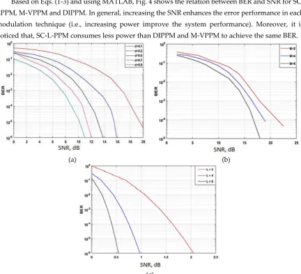
Based on Eqs. (1-3) and using MATLAB, Fig. 4 shows the relation between BER and SNR for SC-LPPM, M-VPPM and DIPPM. In general, increasing the SNR enhances the error performance in each modulation technique (i.e., increasing power improve the system performance). Moreover, it is noticed that, SC-L-PPM consumes less power than DIPPM and M-VPPM to achieve the same BER.
(a) (b)
(c)
Figure 4. Error performance for each modulation scheme: (a) BER versus SNR at different dimming ratios for 2-DIPPM, (b) BER versus SNR at different values of L for SC-L-PPM, (C) BER versus SNR for M-VPPM
at different values of M.
The error performance of DIPPM at different dimming ratios is shown in Fig. 4(a). It shows that, increasing dimming factor, d, the signal to noise ratio, SNR, decreases at a fixed BER. At a specific diming factor, BER is improved by increasing the SNR. The minimum value of SNR needed to enhance error probability form 10-1 to 10-6 is ~ 11 dB.
Figure 4(b) shows the error performance of SC-L-PPM. It indicates that, at a nominated BER value, increasing L from 2 to 8 results in decreasing SNR. Moreover, fixing the value of L will enhance BER performance by incrementing SNR. This is in a fair agreement with the idea of enhancing BER with improving power SNR.
3.1.2 Bit Rate
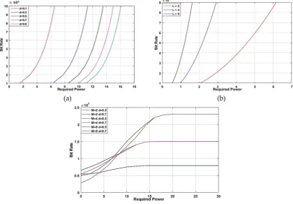
The achievable bit rate for each modulation scheme is displayed in Fig.5. Generally, increasing the power enhances the bit rate.
(a) (b)
(c)
Figure 5. Achievable bit rate for each modulation scheme (a) DIPPM, (b) SC-LPPM, and (c) M-VPPM.
Figure 5(a) shows the relation between bit rate and required power. Fixing d to a definite value leads to enhancing the bit rate but needs a larger amount of power. Also, at a certain bit rate, increasing the diming factor requires more power.
The relation between the required power and bit rate for SC-L-PPM is displayed in Fig. 5(b). At a fixed bit rate, Rb, it is noticed that by increasing L from 2 to 8, it requires less power. Furthermore, at a certain L, increasing bit rate results in a more power required for successful transmission.
The bit rate of M-VPPM is shown in Fig. 5(c) versus SNR at different dimming ratios for different modulation orders. Increasing the modulation order gives rise to developing the bit rate at the same value of SNR. Moreover, it is clearly observed that the dimming ratio increments at the same level of SNR for the same modulation order the bit rate are approximately equal. By applying a certain modulation order, the bit rate is enhanced by increasing the required power of transmission.
3.2 Optical Power Distribution Analysis and Evaluation
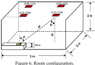
The room under investigation (553 m3) including four identical LED modules equally spaced
Figure 6. Room configuration.
Table 1 introduces the simulation parameters of room, source and receiver. These values are convenient for both lighting and communication purposes.
Table 1 Simulation parameters of room, source and receiver.
Parameters Value
Room Room size 553 m3
Height of desktop surface 1 m
Source Number of LEDs 3600 (6060)
LED transmitted power 20 mW
Semi-angle half power 60o
Center luminous intensity 0.73 cd Power spectrum density (No) 10-21 W/cm2
Receiver Area 1 cm2
Field of view (FOV) 120o
Responsivity 0.4 A/W
Concentrator refractive index 1.9
Filter gain 1
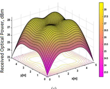
The optical power distribution for each modulation scheme in room topology is shown in Fig.7. It is noted that, the minimum received power values lie at the room corners for DIPPM, SC-L-PPM, and M-VPPM are with value 21, 1.5 and 23 dBm, respectively. The maximum power received is at line of sight (LOS) of the four LEDs and is 26.5 dBm for DIPPM, 7 dBm for SC-L-PPM and 29 dBm for M-VPPM.
(c)
Figure 7. The optical power distribution at the desktop surface: (a) DIPPM, (b) SC-L-PPM, and (c) M-VPPM.
4. Conclusion
In this paper, DIPPM, SC-L-PPM and M-VPPM modulation schemes are utilized for VLC system to allow dimming control and flicker mitigation with a low power consumption, optimum BER, and acceptable bit rate. By comparison, the simulation results indicate that in terms of BER, DIPPM has a BER of 10-6 at SNR ~ 11dB with d = 0.9 while SC-L-PPM has 10-6 BER at SNR ~ 0.5 dB at L = 8. On the
other hand, M-VPPM has a BER of 10-5 with SNR ~ 17 dB. Therefore, SC-L-PPM is the best choice
according to BER with low power requirement for data transmission. Regarding bit rate, the M-VPPM achieves 107 bps whereas both DIPPM and SC-L-PPM reach 106 bps. Consequently, M-VPPM has the
best performance in date rate but at the expense of power required. Concerning the optical power distribution, the maximum obtained power is at the LOS of the four LED module and thus the values 26.5, 7 and 29 dBm for DIPPM, SC-L-PPM and M-VPPM, respectively. On the other hand the minimum obtained optical power is 21 dBm at the corner of the room for DIPPM, 1.5 dBm for SC-L-PPM and 23 dBm for M-VSC-L-PPM. Subsequently, SC-L-SC-L-PPM shows its effectiveness in terms of power efficiency.
References
1. Khan; Ullah, L. Visible light communication: application, architecture, standardization and research challenges. Science Direct. 2017, 3, 78-88. [Available: https://doi.org/10.1016/j.dcan.2016.07.004]
2. Komine, T.; M. Nakagawa, M. Fundamental analysis for visible Light communication system using LED lights. IEEE Transactions on Consumer Electronics. 2004, 50, 100-107. [Available: http://dx.doi: 10.1109/TCE.2004.1277847].
5. Lee, S. H.; Jung, S.Y.; Kwon, J.K. Modulation and coding for dimmable visible light communication. IEEE Communications Magazine. 2015, 53, 136-143. [Available: http://dx.doi: 10.1109/MCOM.2015.7045402]. 6. Yoo, J.H.; Kim, B. W.; Jung, S.-Y. Modelling and analysis of M-ary variable pulse position modulation for
visible light communications. IET Optoelectronics. 2015, 9, 184-190. [Available: http://dx.doi:10.1049/iet-opt.2014.0107].
7. Kim, H.; Din, I. Performance analysis of SC-L-PPM for energy efficient visible light communication. in Consumer Electronics, JeJu Island, South Korea, 22-25 June 2014, [Available: http://dx.doi: 10.1109/ISCE.2014.6884505].
8. Jan, S. U.; Lee, Y.-D.; Koo, I. Comparative analysis of DIPPM scheme for visible light communications. International Conference on Emerging Technologies, ICET, Peshawar, Pakistan, 19-20 Dec. 2015. [Available: http://dx.doi:10.1109/ICET.2015.7389192].
9. Ullah, S.J.; Lee, Y.D. Modeling and analysis of DIPPM: A new modulation scheme for visible light communications. Journal of Sensors. 2015, 2015, 1-8. [Available: http://dx.doi.org/10.1155/2015/963296]. 10. Din, I.; Kim, H. Energy-efficient brightness control and data transmission for visible light communication.
IEEE Photonics Technology Letters. 2014, 26, 781-784. [Available: http://dx.doi: 10.1109/LPT.2014.2306195]. 11. Lee, K.; Park, H. Modulations for visible light communications with dimming control. IEEE Photonics
Technology Letters. 2011, 23, 1136-1138. [Available: http://dx.doi: 10.1109/LPT.2011.2157676].
12. Moon, H.D.; Jung, S.Y. Multi-coded variable PPM for high data rate visible light communications. Journal of the Optical Society of Korea. 2012, 16, 703-708. [Available: http://dx.doi:10.1109/APCC.2012.6388285]. 13. Ghassemlooy, Z.; Popoola, W. P.; Rajbhandari, S. Optical wireless communications - system and channel
![Figure 1. Symbol structure of 2-DIPPM symbol (a) Bit 0 symbol and (b) Bit 1 symbol [9].](https://thumb-us.123doks.com/thumbv2/123dok_us/986606.1598298/3.595.194.393.409.545/figure-symbol-structure-dippm-symbol-bit-symbol-symbol.webp)