REVI E W A RT ICL E
Open Access
Robotic arc welding sensors and
programming in industrial applications
P Kah
*, M Shrestha, E Hiltunen and J Martikainen
Abstract
Technical innovations in robotic welding and greater availability of sensor-based control features have enabled manual welding processes in harsh work environments with excessive heat and fumes to be replaced with robotic welding. The use of industrial robots or mechanized equipment for high-volume productivity has become increasingly common, with robotized gas metal arc welding (GMAW) generally being used. More widespread use of robotic welding has necessitated greater capability to control welding parameters and robotic motion and improved fault detection and fault correction. Semi-autonomous robotic welding (i.e., highly automated systems requiring only minor operator intervention) faces a number of problems, the most common of which are the need to compensate for inaccuracies in fixtures for the workpiece, variations in workpiece dimensions, imperfect edge preparation, and in-process thermal distortions. Major challenges are joint edge detection, joint seam tracking, weld penetration control, and measurement of the width or profile of a joint. Such problems can be most effectively solved with the use of sensory feedback signals from the weld joint. Thus, sensors play an important role in robotic arc welding systems with adaptive and intelligent control system features that can track the joint, monitor in-process quality of the weld, and account for variation in joint location and geometry. This work describes various aspects of robotic welding, programming of robotic welding systems, and problems associated with the technique. It further discusses commercially available seam-tracking and seam-finding sensors and presents a practical case application of sensors for semi-autonomous robotic welding. This study increases familiarity with robotic welding and the role of sensors in robotic welding and their associated problems.
Review Introduction
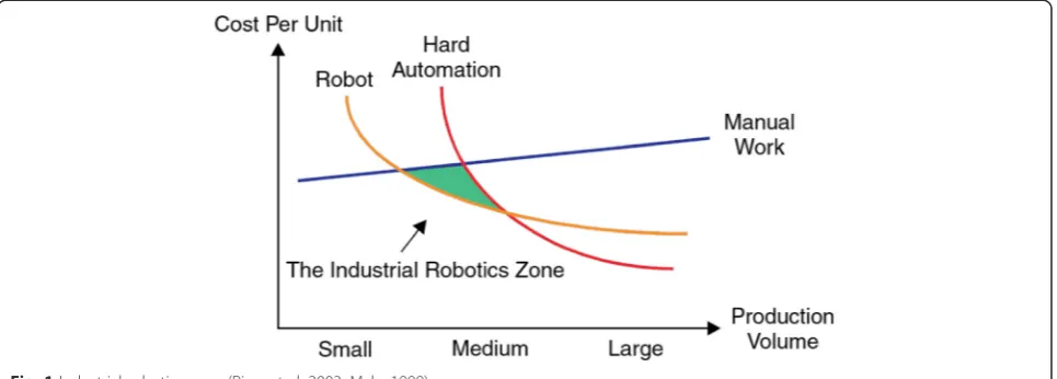
Industrial robots and mechanized equipment have become indispensable for industrial welding for high-volume prod-uctivity because manual welding yields low production rates due to the harsh work environment and extreme physical demands (Laiping et al. 2005). Dynamic market behavior and strong competition are forcing manufacturing companies to search for optimal production procedures. As shown in Fig. 1 (Pires et al. 2003), for small/medium production volumes, robotic production yields the best cost per unit performance when compared to manual and hard automation. In addition to competitive unit costs, robotic welding systems bring other advantages, such as improved productivity, safety, weld quality, flexibility and workspace utilization, and reduced labor costs (Robot et al. 2013a;
Robert et al. 2013). The increase in the range of applica-tions of robotic welding technology has led to a need to re-duce operator input and enhance automated control over welding parameters, path of robotic motion, fault detection, and fault correction (Schwab et al. 2008). Even though the level of complexity and sophistication of these robotic systems is high, their ability to adapt to real-time changes in environmental conditions cannot equal the ability of human senses to adapt to the weld environ-ment (Hohn and Holmes 1982).
According to the Robotics Institute of America, a robot is a “reprogrammable, multifunctional manipulator designed to move materials, parts, tools, or specialized devices, to variable programmed motions for the performance of a var-iety of tasks.”While the first industrial robot was developed by Joseph Engelburger already in the mid-1950s, it was not until the mid-1970s that robotic arc welding was first used in production. Subsequently, robotics has been adopted with many welding processes. The advantages of robotic welding vary from process to process but common benefits
* Correspondence:[email protected]
Laboratory of Welding Technology, Lappeenranta University of Technology, Lappeenranta FI-53851, Finland
generally include improved weld quality, increased prod-uctivity, reduced weld costs, and increased repeatable consistency of welding (Lane 1987).
Robots in arc welding
Welding is an integral part of advanced industrial manu-facturing and robotic welding is considered the main symbol of modern welding technology (Cui et al. 2013). In the earliest applications of robotic welding, so-called first-generation robotic welding systems, welding was per-formed as a two-pass weld system, in which the first pass was dedicated to learning the seam geometry and was then followed by the actual tracking and welding of the seam in the second pass. With developments in technol-ogy came the second generation of robotic welding systems, which tracked the seam in real time, perform-ing simultaneously the learnperform-ing and the seam-trackperform-ing phases. The latest technology in robotic welding is third-generation systems, in which the system not only operates in real time but also learns the rapidly chan-ging geometry of the seam while operating within un-structured environments (Pires et al. 2006). Figure 2 shows the major components of a robotic arc welding system (Cary and Helzer 2005).
The following sections briefly discuss some of the key aspects of robotics in welding technology.
Robotic configurations
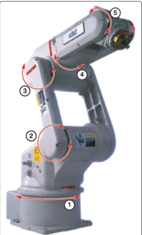
Robots can be categorized based on criteria like degrees of freedom, kinematics structure, drive technology, work-space geometry, and motion characteristics (Tsai 2000). In selection of robots for a specific application, all of these factors need to be considered. Based on the workspace geometry, robots with revolute (or jointed arm) configur-ation are the most commonly used type in industrial ro-botic arc welding (Ross et al. 2010). Figure 3 illustrates an example of a revolute configuration robot.
Phases in welding operations
The welding operation consists of three different phases that need critical consideration in designing a fully auto-mated robotic welding system to achieve good perform-ance and weld quality (Pires et al. 2006):
Preparation phase In this phase, the weld operator sets up the parts to be welded, the apparatus (power source, robot, robot program, etc.) and the weld parameters, along with the type of gas and electrode wires. When CAD/ CAM or other offline programming is used, a robot weld pre-program is available and placed online. Consequently, the robotic program might only need minor tuning for calibration, which can be easily done by the weld operator performing selected online simulations of the process.
Fig. 1Industrial robotics zone (Pires et al. 2003; Myhr 1999)
Welding phase Automatic equipment requires the same capabilities as manual welding, i.e., the system should be capable of maintaining a torch orientation that follows the desired trajectory (which may be different from planned), performing seam tracking, and changing weld parameters in real time, thus emulating the adaptive behavior of manual welders.
Analysis phase The analysis phase is generally a post-welding phase where the post-welding operator examines the obtained weld to ascertain if it is acceptable or whether changes are required in the previous two phases. Use of advanced sensors, such as 3D laser cam-eras, enables execution of this phase online during the welding phase.
Robotic programming modes
Different methods exist for teaching or programming a robot controller; namely, manual methods, online programming (walk-through, lead-through), and offline programming. Manual methods are primarily used for pick-and-place robots and are not used for arc welding robots (Cary and Helzer 2005).
Online programming This category of robotic ming includes lead-through and walk-through program-ming. Use of the manual online programming method requires no special hardware or software on-site other than that which is used for the manufacturing process. The major drawback of online programming is that it is quite inflexible and it is only able to control simple robot paths (Pan et al. 2012a). In the walk-through method, the operator moves the torch manually through the desired sequence of movements, which are recorded into the memory for playback during welding. The walk-through method was adopted in a few early welding robots (Cary and Helzer 2005) but did not gain widespread use. The conventional method for programming welding ro-bots is online programming with the help of a teach pen-dant, i.e., lead-through programming. In this approach, the programmer jogs the robot to the desired position with the use of control keys on the teaching pendant and the desired position and sequence of motions are re-corded. The main disadvantage of the online teaching method is that the programming of the robot causes breaks in production during the programming phase (McWhirter 2012).
Theteach and playback mode has limited flexibility as it is unable to adapt to the many problems that might be encountered in the welding operation, for example, errors in pre-machining and fitting of the workpiece, and in-process thermal distortion leading to change in gap size. Thus, advanced applications of robotic welding require an automatic control system that can adapt and adjust the welding parameters and motion of the welding robots (Hongyuan et al. 2009). Hongyuan et al. (2009) developed a closed loop control system for robots that used teach and playback based on real-time vision sensing for sensing topside width of the weld pool and seam gap to control weld formation in gas tungsten arc welding with gap variation in multi-pass welding. In spite of all the above-mentioned drawbacks, online programming is still the only programming choice for most small to median enter-prises (SMEs). Online programming methods using more intuitive human-machine interfaces (HMI) and sensors in-formation have been proposed by several institutions (Zhang et al. 2006; Sugita et al. 2003). The assisted online programming can be categorized into assisted online pro-gramming and sensor-guided online propro-gramming. Al-though dramatic progress has been carried out to make
online programming more intuitive, less reliant on oper-ator skill, and more automatic, most of the research outcomes are not commercially available aside from Sugita et al. 2003.
Offline programming Offline programming (OLP) with simulation software allows programming of the welding path and operation sequence from a computer rather than from the robot itself. 3D CAD models of the workpieces, robots, and fixtures used in the cell are required for OLP. The simulation software matches these 3D CAD models, permitting programming of the robot’s welding trajectory from a computer instead of a teaching pendant in the welding cell as in online programming. After simulation and testing of the program, the instructions can be exported from the computer to the robot controller via an Ethernet communication network. Ongoing research sug-gests, however, that the use of sensing technology would make it feasible to completely program the final trajectory only with OLP (Miller Electric Mfg Co. 2013). Pan et al. (2012a) developed an automated offline programming method with software that allows automatic planning and programming (with CAD models as input) for a robotic welding system with high degrees of freedom without any programming effort. The main advantages of OLP are its reusable code, flexibility for modification, ability to gener-ate complex paths, and reduction in production downtime in the programming phase for setup of a new part. Never-theless, OLP is mostly used to generate complex robot paths for large production volumes because the time and cost required to generate code for complex robotic systems is similar to if not greater than with online programming (Pan et al. 2012a). Currently, for a complex manufacturing process with small to median production volume, very few robotic automation solution are used to replace manual production due to this expensive and time-consuming pro-gramming overhead. Although OLP has the abovemen-tioned advantages, it is not popular for small to median enterprise (SME) users due to its obvious drawbacks. It is difficult to economically justify an OLP for smaller product values due to the high cost of the OLP package and pro-gramming overhead required to customize the software for a specific application. Development of customized software for offline programming is time-consuming and requires high-level programming skills. Typically, these skills are not available from the process engineers and operators who often perform the robot programming in-process today. As OLP methods rely accurate modeling of the robot and work cell, additional calibration procedures using extra sensors are in many cases inevitable to meet re-quirements (Pan et al. 2012b).
Intelligent robot It is very difficult and even impossible to anticipate and identify all situations that the robot
could do during his task execution. Therefore, the soft-ware developer must specify the categories of situation and provide the robot with sufficient intelligence and the ability to solve problems of any class of its program. Sometimes, when situations are ambiguous and uncer-tain, the robot must be able to evaluate different possible actions. If the robot’s environment does not change, the robot is given a model of its environment so that it can predict the outcome of his actions. But if the environ-ment changes, the robot should learn. This is among other prerequisites, which calls for the development and embedding in robots’system of artificial intelligence (AI) capable of learning, reasoning, and problem solving (Tzafestas and Verbruggen 1995).
The most welding robots serving in practical production still are the teaching and playback type and cannot well meet quality and diversification requirements of welding production because these types of robots do not have the automatic functions to adapt circumstance changes and un-certain disturbances (errors of pre-machining and fitting workpiece, heat conduction, dispersion during welding process) during welding process (Tarn et al. 2004; Tarn et al. 2007). In order to overcome or restrict different un-certainty which influences the quality of the weld, it would be an effective approach to develop and improve the intelli-gent technology of welding robots such as vision sensing, multi-sensing for welding robots, recognition of welded en-vironment, self-guiding and seam-tracking, and intelligent real-time control procedures for welding robots. To this end, the development of an intelligence technology to improve the current method of learning and use for playback programming for welding robots is essential to achieve high quality and flexibility expected of welded products (Chen and Wu 2008; Chen 2007).
Intelligent robots are expected to take an active role in the joining job, which comprises as large a part of the ma-chine industry as the machining job. The intelligent robot can perform highly accurate assembly jobs, picking up a workpiece from randomly piled workpieces on a tray, as-sembling it with fitting precision of 10 μm or less clear-ance with its force sensors, and high-speed resistant spot arc welding in automotive welding and painting. However, the industrial intelligent robots still have tasks in which they cannot compete with skilled workers, though they have a high level of skills, as has been explained so far. Such as assembling flexible objects like a wire harness, there are several ongoing research and development activ-ities in the world to solve these challenges (Nof 2009).
Problems in robotic welding
The consistency required for making part after part, which, in the absence of proper control, might fluctuate due to poor fixturing or variations in the metal forming process.
In the case of low to medium volume manufacturing or repair work, the time and effort taken to program the robot to weld a new part can be quite high (Dinham and Fang2013).
Robotic welding requires proper joint design, consistent gap conditions and gap tolerance not exceeding 0.5 to 1 mm. Variation in gap condition requires the use of sensing technologies for gap filling (Robot et al.2013b).
Automation of welding by robotic systems has high initial cost, so accurate calculation of return on investment (ROI) is essential (Rochelle2010). Possible shortages of skilled welders with the
requisite knowledge and training pose limitations. Unlike adaptive human behavior, robots cannot
independently make autonomous corrective
decisions and have to be supplemented by the use of sensors and a robust control system for decision-making.
Robotic welding cannot easily be performed in some areas like pressure vessels, interior tanks, and ship bodies due to workspace constraints (Robotics Bible
2011).
The majority of sensor-based intelligent systems available in the market are not tightly integrated with the robot controller, which limits the perform-ance of the robotic system as most industrial robots only offer around a 20-Hz feedback loop through the programming interface. Consequently, the robot cannot respond to the sensor information quickly, resulting in sluggish and sometimes un-stable performance.
Sensors in robotic welding Need for sensors in robotic welding
At present, welding robots are predominantly found in automatic manufacturing processes, most of which use teach and playback robots that require a great deal of time for training and path planning, etc. Furthermore, teaching and programming needs to be repeated if the dimensions of the weld workpieces are changed, as they cannot self-rectify during the welding process. The seam position in particular is often disturbed in prac-tice due to various problems. The use of sensors is a way to address these problems in automated robotic welding processes (Xu et al. 2012). The main use of sensors in robotic welding is to detect and measure process features and parameters, such as joint geom-etry, weld pool geometry and location, and online con-trol of the welding process. Sensors are additionally
used for weld inspection of defects and quality evalu-ation (Pires et al. 2006). The ideal sensor for robot ap-plication should measure the welding point (avoidance of tracking misalignment), should detect in advance (finding the start point of the seam, recognizing cor-ners, avoiding collisions), and should be as small as possible (no restriction in accessibility). The ideal sen-sors, which combine all three requirements, do not exist; therefore, one must select a sensor which is suit-able for the individual welding job (Bolmsjö and Olsson 2005). Sensors that measure geometrical parameters are mainly used to provide the robot with seam-tracking capability and/or search capability, allowing the path of the robot to be adapted according to geometrical devia-tions from the nominal path. Technological sensors measure parameters within the welding process for its stability and are mostly used for monitoring and/or controlling purposes (Pires et al. 2006). Table 1 pre-sents different sensor applications, and summarized ad-vantages, and drawbacks for a specific time during welding operation.
Contact-type sensors, like nozzle or finger, are less expensive and easier to use than a non-contact. How-ever, this type of sensors cannot be used for butt joints and thin lap joints. Non-contact sensors referred as through-the-arc sensors may be used for tee joints, U and V grooves, or lap joints over a certain thickness. These types of sensors are appropriate for welding of bigger pieces with weaving when penetration control is not necessary. However, it is not applicable to materials with high reflectivity such as aluminum. Great attention has been paid to joint sensing by welding personnel since the 1980s. The principal types of industrial arc-welding sensors that have been employed are optical and arc sensors (Nomura et al. 1986). Some of the most important uses of sensors in robotic welding are discussed below:
Seam finding Seam finding (or joint finding) is a process in which the seam is located using one or more searches to make sure that the weld bead is precisely de-posited in the joint. Seam finding is done by adjusting the robotic manipulator and weld torch to the right pos-ition and orientation in relation to the welding groove or by adjusting the machine program, prior to welding (Servo Robot Inc 2013a). Many robotic applications, especially in the auto industry, involve producing a series of short and repeated welds for which real-time tracking is not required; however, it is necessary to begin each weld in the correct place, which necessitates the use of seam-finding sensors (Meta Vision Systems Ltd 2006).
the robotic manipulator accordingly; to counter the effects of variation in the seam caused by distortion, un-even heat transfer, variability of gap size, staggered edges, etc. (Xu et al. 2012).
Reliable seam-tracking sensors provide the following advantages (Björkelund 1987):
Automatic vertical and horizontal correction of the path (even path changes necessitated by thermal distortion)
Less stringent accuracy demands on objects and fixtures
Welding parameter adaptation Reduced programming time Lower rejection rates Higher welding quality Viability of short series
Adaptive control In adaptive control welding, i.e., a closed loop system using feedback-sensing devices and adaptive control, there is a process control system that detects changes in welding conditions automatically with the aid of sensors and directs the equipment to take appropriate action. Sensors are needed in adaptive con-trol welding to find the joint, assess root penetration,
conduct bead placement and seam tracking, and ensure proper joint fill (Cary and Helzer 2005). Use of sensors allows adaptive control for real-time control and adjust-ment of process parameters such as welding current and voltage. For example, the capabilities of sensors in seam finding, identification of joint penetration and joint fill-ing, and ensuring root penetration and acceptable weld bead shape mean that corrective modification of relevant welding parameters is done such that constant weld quality is maintained (Cary and Helzer 2005; Drews and Starke 1986). An adaptive welding robot should have the capabilities to address two main aspects. The first aspect is the control of the end effector’s path and orientation so that the robot is able to track the joint to be welded with high precision. The second one is the control of welding process variables in real time, for example, the control of the amount of metal deposition into the joint as per the dimensions of the gap separating the parts to be welded.
Chen et al. (2007) studied the use of laser vision sensing for adaptive welding of an aluminum alloy in which the wire feed speed and the welding current are adjusted auto-matically as per the groove conditions. The sensor was used to precisely measure the weld groove and for automatic seam tracking involving automatic torch traverse alignment
Table 1Applications and quality of sensors Operation time Type of sensors Advantages Drawbacks Sensing independent Touch sensing
Can recognize 3-dimensional offset of the workpiece. The wire tip or the gas nozzle can serve as a sensor. Can be used for accurate learning of the path before welding.
Can defect elastically, using tactile probes it is difficult, if not impossible, to provide information on the joint fit up. Poor weld joint repeatability.
Preview sensing
Contact sensing
Relatively low cost. The mechanically probes leads the welding spots.
Not adaptable to suit a variety of joint geometries.
Inductive sensing
Largely used in industry, configurations with one pick-up coil can provide a cross-seam or vertical path correction signal.
Different sensor is needed for each type of joint, should stay very close to the joint
Capacitive sensing
Offer the opportunity to measure the distance between the workpiece and an electrically conduction plate of small dimension.
It is hard to extract a correction signal in two direction from the capacity variations
Acoustical sensing
Apart from seam-tracking application, an acoustical sensing system can be used to explore the workpiece for obstacle and maybe to inspect a produced weld.
Line of sight must not deviate from the surface normal; another limitation is the temperature dependence of the speed of the sound.
Optical sensing
Can be used for seam tracking as well as for geometrical recognition of the weld pool, to adapt process parameters in the case of possible deviations.
To prevent accessibility limitation, it may require additional axes for seam tracking, tremendous effort to introduce technical integration, regularly check the lens protection.
On-the-spot sensing
Weld pool observation
Dedicated to welding pool geometry and properties. The obtained image is processed and pattern recognition algorithms are used to extract the dimensions and form of the weld pool. Different sensors can be applied: optic sensing, thermal sensing, real-time radiography, weld pool oscillation sensing,
There should be a clear interpretation of the image by the system, in order to give torch corrective changes accordingly
Through-the-arc sensing
No additional voluminous sensor needs to be fixed to the weld torch. Its simple operation and implementation have made arc sensing a commonly accepted off-the-shelf technique.
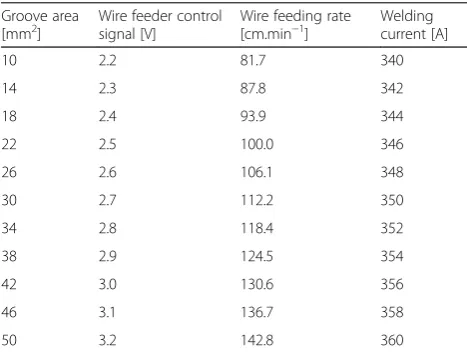
and torch height adjustment during welding. An adaptive software was employed that calculated the wire feed rate according to the variation in the gap and the weld area. The software included extraction of groove geometry, cal-culation and filtering, querying of the adaptive table (ADAP table as shown in Table 2), and generation of the control output signal.
Figure 4 shows the control flow module for adaptive control of weld parameters for the system.
The process of adaptive control consisted of calcula-tion of groove area from geometry data transmitted from the image processing module, followed by filtering of the calculated area data to remove invalid data and noise. Next, the module queried the ADAP table to get the proper welding parameters, i.e., weld current and wire feed rate. The corresponding values of analog signals were then transmitted to control the power source and the wire feeder (Chen et al. 2007).
Quality monitoring Use of automatic weld quality moni-toring systems results in reduced production costs through the reduced manpower required for inspection. An automatic detection system for welding should be able to classify weld defects like porosity, metal spatter, irregu-lar bead shape, excessive root reinforcement, incomplete penetrations and burn-through. Most commercial moni-toring systems work in a similar way: voltage, current, and other process signals are measured and compared with preset nominal values. An alarm is triggered when any difference from the preset values exceeds a given threshold. The alarm thresholds are correlated with real weld defects or relate to specifications defined in the weld-ing procedure specification (WPS) (Pires et al. 2006). Currently, common nondestructive testing methods for inspection of weld bead include radiography, ultrasonic,
vision, magnetic detection, and eddy current and acoustic measurements (Abdullah et al. 2013).
Quinn et al. (1999) developed a method for detection of flaws in automatic constant-voltage gas metal arc welding (GMAW) using the process current and voltage signals. They used seven defect detection algorithms to process the current and voltage signals to get quality pa-rameters and flag welds that were different from the baseline record of previously made defect-free welds. The system could effectively sense melt-through, loss of shielding gas, and oily parts that cause surface and sub-surface porosity.
Figure 5 shows an example of a visual weld inspection system (VIROwsi from Vitronic GmbH) consisting of a camera-based sensor, computing unit, and software having the capability of fully automated three-dimensional seam inspection with combined 2D and 3D machine vision. It can detect all the relevant defects and their position in real time. These informations can be stored for later follow-up, documentation, and statistical evaluation (VITRONIC 2010).
Figure 6 shows an example of a weld inspection sen-sor based on a scanning thermal profile called ThermoProfilScanner (TPS), from HKS Prozesstechnik GmbH, for evaluation of weld quality and misalign-ment of welds during cooling. As the characteristics of the thermal profile (symmetry, width of a thermal zone, maximum temperature, etc.) and the seam quality are directly correlated, seam abnormalities like insufficient weld penetration, weld seam offset, holes, lack of fusion, etc. can be detected by TPS. Correlations between thermal profile and weld quality from previous experience can be used to compare the desired values and tolerances. When tolerance limits are exceeded, warning signals are pro-duced marking the defective points and the weld process can be stopped (HKS Prozesstechnik 2013).
Seam-tracking and seam-finding sensors
Several sensors for robotic welding, mainly for seam tracking and quality control, are commercially available. Some of the more renowned sensor products in the field of robotic welding are discussed below:
Robo-Find (Servo Robot Inc)
The sensor in the Robo-Find system for seam finding in robotic welding is based on a laser vision system. Robo-Find provides a solution for offline seam-finding applica-tions where parts and/or features must first be located when modifying the tool path. It locates, detects, and mea-sures weld joints without any contact with the part and then signals the robot to adjust torch trajectory in less than 1 s. Some of the features and benefits of Robo-Find (Servo Robot Inc) are listed below (Servo Robot Inc 2013a):
Table 2Adaptive welding parameters table (ADAP table) (Chen et al. 2007)
Groove area
[mm2] Wire feeder controlsignal [V] Wire feeding rate[cm.min−1] Weldingcurrent [A]
10 2.2 81.7 340
14 2.3 87.8 342
18 2.4 93.9 344
22 2.5 100.0 346
26 2.6 106.1 348
30 2.7 112.2 350
34 2.8 118.4 352
38 2.9 124.5 354
42 3.0 130.6 356
46 3.1 136.7 358
It is immune to arc process like spatter and can withstand radiated heat.
It can find seams for all weldable materials. It has an embedded color video camera for remote
monitoring and programming.
It has the ability to recognize joint type automatically.
It reduces repair and rework.
It can be retrofitted to existing equipment.
It employs smart camera technology with embedded control unit (no separate controller with everything inside the camera itself ) such that setup can be done with a simple laptop interface.
Robo-Find is available with one of two types of laser camera, based either on a point laser sensor or on a line laser sensor system. Figure 7 shows the Robo-Find SF/D-HE system, which is based on a line laser system, and the SENSE-I/D-V system, based on a point laser. An approximate comparison of the time requirement between the laser-based vision sensor and a mechanical tactile sensor for seam finding and welding is shown in Fig. 8.
Power-Trac (Servo Robot Inc) This sensor has the capability of real-time seam tracking and offline seam finding based on a laser vision system. The trajectory of the torch is modified continuously to compensate for real-time changes such as warping caused by heat input
during the welding process. Some of the features and benefits as mentioned by the manufacturer are as fol-lows (Pires et al. 2006):
1. It is a fully integrated system complete with laser camera, control unit, and software.
2. It offers automatic joint tracking and real-time trajectory control of the welding torch.
3. There is an option for an inspection module for quality control of the welds.
4. It is immune to the arc process like spatter and can withstand radiated heat.
5. The system is unaffected by ambient lighting conditions and can track all weldable materials. 6. The system offers true 3D laser measurements of
joint geometry dimensions.
7. The high-speed digital laser sensor makes fast and reliable joint recognition possible.
8. The system is suitable for high-speed welding pro-cesses like tandem gas metal arc welding and laser hybrid welding.
9. The system has a direct interface with most brands of robot by advanced communication protocol on a serial or Ethernet link.
10.A large joint library is included, which allows almost any weld seam on any weldable material to be tracked and measured geometrically.
11.The adaptive welding module can adjust for joint geometry variability for optimization of the size of the weld and thus elimination of defects and reduced over-weld.
Figure 9 shows robotic arc welding in conjunction with the Power-Trac system for seam finding and track-ing (Servo Robot Inc 2013b).
Laser Pilot (Meta Vision Systems Ltd.) This sensor featuring laser vision enables sensing of the actual parts to be welded for seam finding and seam tracking. It corrects part positioning errors as well as errors due to thermal distortion during the welding process. Some of the variants of the Laser Pilot system are de-scribed below:
Laser Pilot MTF
Laser Pilot MTF is a seam finder and can be used in robotic welding applications which involve a series
Fig. 4Diagram of welding parameter adaptive control (Chen et al. 2007)
of short welds, as commonly found in the
automotive industry, that do not require real-time tracking, although correct placement of the weld torch in the beginning of the weld is needed. MTF uses a standard interface for communication to the robot controller.
Laser Pilot MTR
Laser Pilot MTR is a seam tracker and available with interfacing with various leading robot manufacturers’ products. In addition to the seam-finding function, it can track seams in real time while welding (Meta Vision Systems Ltd2006).
Fig. 6Measurement of thermal field of seam during cooling of a weld setup of TPS (a), a faulty weld (b), and an abnormal thermal profile (c) of the faulty weld (HKS Prozesstechnik 2013)
Circular Scanning System Weld-Sensor The Circular Scanning System (CSS) Weld-Sensor (Oxford Sensor Technology Ltd.) consists of a low-power laser diode that projects a laser beam through an off-axis lens onto the surface being analyzed, as shown in Fig. 10. A linear CCD detector views the spot through the same off-axis lens. The distance between the CSS Weld-Sensor and the surface to be measured is calculated based on a triangulation method. An inbuilt motor rotates the off-axis lens, causing the laser spot to be rotated and forming a conical scan (Mortimer 2006). The circular scanning technology enables measurement of 3D shaped corners in a single measurement and has the advantage of an increased detection ratio compared to other sensors (Bergkvist 2004). The CSS Weld-Sensor can also be used with highly reflective materials such as aluminum (Mortimer 2006).
A manufacturing system designed by Thyssen-Krupp-Drauz-Nothelfer (TKDN) with integrated CSS Weld-Sensor in conjunction with a MIG welding torch and an ABB 2400–16 robot was used in welding of the aluminum C-pillar to the aluminum roof section of Jaguar’s sports car XK, as shown in Fig. 11. This welding has importance as regards both esthetics and strength because the sec-tion is at eye level and there should not be any visible external joints and defects. The sensor reads the seam’s position, width, depth, and orientation. There are some six or eight measurements involved in the welding process and each measurement takes less than 400 ms. The system employed one CSS Weld-Sensor to measure the true position of the seam prior to
Fig. 8Comparison between laser vision and tactile sensing system for seam finding and welding (Servo Robot Inc 2013a)
welding, allowing optimization of the programmed weld path by automatic correction for component tol-erances and fit-up variation (Nomura et al. 1986).
ABB Weldguide III Weldguide III is a through-the-arc seam-tracking sensor developed by ABB that uses two external sensors for the welding current and arc voltage. It has a measurement capacity at 25,000 Hz for quick and accurate path corrections and can be integrated with various transfer modes, like spray-arc, short-arc, and pulsed-arc GMAW.
Weldguide III has basic, advanced, and multi-pass modes of tracking. The basic tracking modes consist of either to-work mode or centerline mode. In work mode, height is sensed, and in fixed torch-to-work, distance is maintained by measuring the target current and adjusting the height to maintain the setting,
as shown in Fig. 12a. Centerline mode is used with weaving, where the impedance is measured as the torch moves from side-to-side using the bias parameter, as il-lustrated in Fig. 12b (ABB Group 2010).
In adaptive fill mode, a type of advanced tracking mode, the robot can identify and adjust for variations in joint tolerances. If the joint changes in width, the robot’s weave will increase or decrease and travel speed is adjusted accordingly as shown in Fig. 13.
For multi-pass welding, Weldguide III tracks the first pass and stores the actual tracked path so that it can offset for subsequent passes, as shown in Fig. 14.
A practical case: MARWIN Targeted problem
Currently available welding technologies such as manual welding and welding robots have several drawbacks.
Fig. 10Arrangement of parts with an off-center lens in CSS (Braggins 1998)
Manual welding is time-consuming, while existing robot are not efficient enough for manufacturing small batch-sized products but they also often face discrepancies when reprogramming is necessary. This reprogramming is also extremely time-consuming.
A project named MARWIN, a part of the European Research Agency FP7 project framework, was initiated in November 2011 (CORDIS 2015). Its aim was to de-velop a vision-based welding robot suitable for small-and medium-sized enterprises (SMEs) with automatic track calculation, welding parameter selection, and an embedded quality control system (Chen et al. 2007). MARWIN can extract welding parameters and calcu-late the trajectory of the end effector directly from the CAD models, which are then verified by real-time 3D scanning and registration (Rodrigues et al. 2013a). The main problem for SMEs trying to use robotic welding is that products are changed after small batches and the extensive reprogramming necessary is expensive and time-consuming. Limitations of current OLP include manufacturing tolerances between CAD and work-pieces and inaccuracies in workpiece placement and
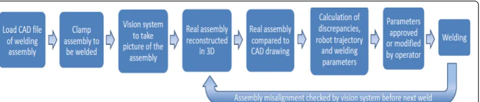
modeled work cell (TWI Ltd 2012). Figure 15 shows the overall process diagram for the MARWIN system.
Programming
The MARWIN system consists of a control computer with a user interface and controls for the vision system and the welding robot. The new methodology for robotic offline programming (OLP) addressing the issue of auto-matic program generation directly from 3D CAD models and verification through online 3D reconstruction. The vision system is capable of reconstructing a 3D image of parts using structured light and pattern recognition, which is then compared to a CAD drawing of the real assembly. It extracts welding parameters and calculates robot trajectories directly from CAD models which are then verified by real-time 3D scanning and registration. The computer establishes the best robotic trajectory based on the user input. Automatic adjustments to the trajectory are done from the reconstructed image. The welding parameters are automatically chosen from an in-built database of weld procedures (TWI Ltd 2012). The user’s role is limited to high-level specification of the welding task and confirmation and/or modification of weld parameters and sequences as suggested by MARWIN (Rodrigues et al. 2013a). The MARWIN con-cept is illustrated in Fig. 16.
Sensing
The vision system in MARWIN is based on a structured light scanning method. As shown in Fig. 17, multiple planes of light of known pattern are projected onto the target surface, which is recorded by a camera. The spatial relationship between the light source and the camera is then combined with the shape of the captured pattern to get the 3D position of the surface along the pattern. The advantages of such system are that both camera and projector can be placed as close together as practically possible which may offer advantages to design miniaturization. Moreover, the mathematical formula-tion of such arrangement is simple than those of
Fig. 12aTorch to work mode andbcenterline mode (ABB Group 2010)
standard scanners which results in less computing cycles, thus, making the parallel design more appropriate for 3D real-time processing (Rodrigues et al. 2013a).
Results
The parallel arrangement requires 35 % fewer arithmetic operations to compute a point cloud in 3D being thus more appropriate for real-time applications. Experiments show that the technique is appropriate to scan a variety of surfaces and, in particular, the intended metallic parts for robotic welding tasks (Rodrigues et al. 2013b). The method allows the robot to adjust the welding path de-signed from the CAD model to the actual workpiece. Alternatively, for non-repetitive tasks and where a CAD model is not available, it is possible to interactively define the path online over the scanned surface (Rodrigues et al. 2013c).
Conclusions
Robotics and sensors, together with their associated control systems have become important elements in in-dustrial manufacturing. They offer several advantages, such as improved weld quality, increased productivity, reduced weld costs, increased repeatable consistency of welding, and minimized human input for selection of weld parameters, path of robotic motion, and fault detection and correction.
Continuous development in the field of robotics, sen-sors, and control means that robotic welding has reached the third-generation stage in which a system can operate in real-time and can learn rapid changes in the geometry of the seam while operating in unstruc-tured environments.
Of the programming methods commonly used with welding robots, conventional online programming with a teach pendant, i.e., lead-through programming, has the disadvantage of causing breaks in production during programming. Furthermore, it is only able to control simple robot paths. Offline programming, due to its reusable code, flexibility of modification, and ability to generate complex paths, offers the benefit of a reduction in production downtime in the programming phase for setup of new parts and supports autonomous robotic welding with a library of programming codes for weld parameters and trajectories for different 3D CAD models of workpieces.
Despite the advantages of sensor-based robotic weld sys-tems, there are some issues associated with robotic weld-ing that need to be addressed to ensure proper selection based on work requirements and the work environment.
A variety of sensors are used in robotic welding for detection and measurement of various process fea-tures and parameters, like joint geometry, weld pool geometry, location, etc., and for online control of the
Fig. 14Multi-pass welding by Weldguide III (ABB Group 2010)
weld process. The primary objectives of these sensors, along with the control system, are seam finding, seam tracking, adaptive control, and quality monitoring of welds.
The use of sensors is not new in this field, and sensors have successfully been used for seam tracking for more than 20 years in robotic arc welding. Basically, two dif-ferent principles are used, through-arc sensing and op-tical sensors. Through-arc sensing uses the arc itself and requires a small weaving motion of the weld torch. Op-tical sensors are often based on a scanning laser light and triangulation to measure the distance to the weld joint. Both methods have some characteristic features that make them more suitable in certain situations. It should be noted that the through-arc sensing technique
is rather inexpensive in comparison with an optical seam tracker. The principal types of industrial arc-welding sensors that have been employed are optical and arc sensors. If the arc sensing has been dominant till the 1980s, the trend nowadays is focused on optical im-provement for intelligent programming as well as intelli-gent sensors.
Many sensors for seam tracking and seam finding are available in the market. The nature of the work defines the suitability of a particular type of sensor. However, due to an acceptable level of accuracy and reasonable cost, vision-based sensors are mostly used for seam tracking in most robotic weld applications, apart from through-the-arc sensing.
The research-based project MARWIN presented a semi-autonomous robotic weld system in which vision sensors scan the work piece assembly in 3D using structured light, which is compared to the CAD drawing to calculate the robot trajectory and weld parameters from an inbuilt data-base. This approach eliminates the necessity of tedious pro-gramming for robotic and welding parameters for each individual work part and the role of the user is limited to high-level specification of the welding task and confirm-ation and/or modificconfirm-ation if required. SMEs with small pro-duction volumes and varied workpieces stand to benefit greatly from such semi-autonomous robotic welding.
Until recently, most robot programs were only taught through the robot teach pendant, which required the robot system to be out of production. Now, programmers are using offline program tools to teach the robot move-ments. After transferring the program to the robot con-troller, they use the robot teach pendant to refine the program positions. This greatly improves the productivity
Fig. 16MARWIN concept (TWI Ltd. 2012)
of the robot system. But still, calibration is needed be-tween the model and the real work cell. The trend is the development of more intelligent programming, by use of sensors with the ability to scan the workpiece and working environment with high accuracy.
Competing interests
The authors declare that they have no competing interests.
Authors’contributions
All the authors have drafted the manuscript. All authors read, analyzed, and approved the final manuscript.
Received: 20 March 2014 Accepted: 24 April 2014
References
Abdullah, BM, Mason, A, & Al-Shamma’a, A. (2013). Defect detection of the weld bead based on electromagnetic sensing.Journal of Physics: Conference Series, 450, 1–6.
Bergkvist, P. (2004).Seam tracking in a complex aerospace component for laser welding. Department of Technology, Mathematics and Computer Technology, Sweden: University of Trollhattan.
Björkelund, M (1987). A true seam tracker for arc welding. JD Lane (Ed.),Robotic Welding(p. 167). IFS (Publications) Ltd.
Bolmsjö, G, & Olsson, M (2005). Sensors in robotic arc welding to support small series production.Industrial Robot: An International Journal, 32(4), 341–345. Braggins, D. (1998). Oxford Sensor Technology - a story of perseverance.Sensor
Review, 18(4), 237–241.
Cary, HB, & Helzer, SC. (2005).Modern welding technology. New Jersey: Pearson Education. pp. 326–329.
Chen, SB. (2007). On the key intelligentized technologies of welding robot.LNCIS, 362, 105–116.
Chen, SB, & Wu, J. (2008).Intelligentized technology for arc welding dynamic process. LNEE(Vol. 29). Heidelberg: Springer.
Chen, Z, Song, Y, Zhang, J, Zhang, W, Jiang, L, & Xia, X. (2007). Laser vision sensing based on adaptive welding for aluminum alloy.Frontiers of Mechanical Engineering, 2(2), 218–223.
Cui, H, Dong, J, Hou, G, Xiao, Z, Chen, Y, & Zhao, Z. (2013).“Analysis on arc-welding robot visual control tracking system”, in 2013 International Conference on Quality, Reliability, Risk, Maintenance, and Safety Engineering (QR2MSE). Dinham, M, & Fang, G. (2013). Autonomous weld seam identification and localisation using eye-in-hand stereo vision for robotic arc welding.
Robotics and Computer-Integrated Manufacturing, 29(5), 288–301. Drews, P, and Starke, G (1986). Development approaches for advanced adaptive
control in automated arc welding.Mechatronics Dept., Univ. of Achen, Germany, Internal Report 12.
Group, ABB. (2010).Weldguide III thru-the-arc seam tracking.
Hohn, RE, & Holmes, JG. (1982).“Robotic arc welding - adding science to the art”, in Robots VI. Michigan: Detroit.
Hongyuan, S, Xixia, H, & Tao, L. (2009). Weld formation control for arc welding robot.International Journal of Advanced Manufacturing Technology, 44, 512–519.
Laiping, C. Shanben and L. Tao,“The modeling of welding pool surface reflectance of aluminum alloy pulse GTAW,”Materials Science and Engineering: A, vol. 394, no. 1–2, p. A 320–326, 2005
Lane, JD. (1987).“Robotic welding state of the art”, in Robotic welding - International trends in manufacturing technology(pp. 1–10). Bedford: IFS (Publications) Ltd.
McWhirter, K.“Welding robot programmability,”Wolf Robotics, 24 January 2012. [Online]. Available: http://www.cimindustry.com/article/welding/welding-robot–programmability. [Accessed: 14 July 2015].
Meta Vision Systems Ltd. (2006). Robotic. [Online]. Available: www.meta-mvs.com/ app/images/Robot-Welding-Applications.pdf. [Accessed: 14 July 2015] CORDIS. (2015).Decision making and augmented reality support for automatic
welding installations.[Online] Available at: http://cordis.europa.eu/project/rcn/ 101118_en.html. [Accessed 14 07 2015].
Mortimer, J. (2006). Jaguar uses adaptive MIG welding to join C-pillars to an aluminium roof section in a new sports car.Sensor Review,
26(4), 272–276.
Myhr, M. (1999).“Industrial new trends: ABB view of the future”, in International Workshop on Industrial Robotics. Lisbon: New Trends and Perspectives. Nof, SY. (2009).Springer handbook of automation(pp. 349–363). London: Springer
Dordrech Heidelberg.
Nomura, H, Sugitani, Y and Suzuki, Y. (1986).Automatic control of arc welding by arc sensors system, NKK Technical Report, Overseas No 47.
Pires, JN, Loureiro, A, & Bölmsjo, G. (2006a).Welding robots: technology. London: System Issue and Application. Springer-Verlag. p. 74.
Miller Electric Mfg Co.,“Offline programming and simulation in robotic welding applications speeds up programming time, reduces robot downtime,”2013. [Online]. Available: http://www.millerwelds.com/resources/articles/offline- programming-simulation-automated-robotic-welding-automation-Miller-welding-automation-DTPS. [Accessed 2 April 2013].
Pan, Z, Polden, J, Larkin, N, Duin, SV, & Norrish, J. (2012a)."Automated Offline Programming for Robotic Welding System with High Degree of Freedoms," in Advances in Computer, Communication, Control and Automation
(Vol. 121, pp. 685–692). Berlin: Springer Berlin Heidelberg. Pan, Z, Polden, J, Larkin, N, Van Duin, S, & Norrish, J. (2012b).“Recent
progress on programming methods for industrial robots”.Robotics and Computer Integrated Manufacturing, 28(2), 87–94.
Pires, JN, Loureiro, A, Godinho T, Ferreira P, Fernando B, Morgado J. (2003). “Welding robots,”IEEE Robotics & Automation Magazine,45–55. Pires, JN, Loureiro, A, & Bölmsjo, G. (2006b).Welding robots - technology system
issues and applications. London: Springer.
HKS Prozesstechnik,“ThermoProfilScanner - TPS,”2013. [Online]. Available: http:// www.hks-prozesstechnik.de/fileadmin/uploads/Downloads/flyer_tps_engl.pdf. [Accessed: 14 July 2015].
HKS Prozesstechnik,“ThermoProfilScanner,”HKS Prozesstechnik, [Online]. Available: http://www.hks-prozesstechnik.de/en/products/ thermoprofilscanner/. [Accessed 25 September 2013].
Quinn, TP, Smith, C, McCowan, CN, Blachowiak, E, & Madigan, RB. (1999). Arc sensing for defects in constant voltage gas metal arc welding.Welding Journal, 78, 322-s.
Robert, G.“Top 5 Advantages of Robotic Welding,”Robotiq, 20 February 2013. [Online]. Available: http://blog.robotiq.com/bid/63115/Top-5-Advantages -of-Robotic-Welding. [Accessed 1 May 2013].
Robot Welding,“Benefits of robotic welding,”[Online]. Available: http:// www.robotwelding.co.uk/benefits-of-robot-welding.html. [Accessed 1 May 2013].
Robot Welding,“Key issues for robotic welding,”[Online]. Available: http:// www.robotwelding.co.uk/key-issues.html. [Accessed 4 September 2013]. Robotics Bible,“Arc welding robot,”11 September 2011. [Online]. Available:
http://www.roboticsbible.com/arc-welding-robot.html. [Accessed 12 May 2013].
Rochelle, B.“Think before you integrate (robotic welding),”thefabricator.com,1 March 2010.
Rodrigues, M, Kormann, M, Schuhlerb, C, Tomek, P (2013). An intelligent real time 3D vision system for robotic welding tasks.International Symposium on Mechatronics and its Applications, Amman.
Rodrigues, M, Kormann, M, Schuhler, C, & Tomek, P. (2013b). Structured light techniques for 3D surface reconstruction in robotic tasks. InProceedings of the 8th International Conference on Computer Recognition Systems CORES 2013 Advances in Intelligent Systems and Computing
(Vol. 226, pp. 805–814).
Rodrigues, M, Kormann, M, Schuhler, C, & Tomek, P. (2013c). Robot trajectory planning using OLP and structured light 3D machine vision.Advances in Visual Computing Lecture Notes in Computer Science, 8034, 244–253. Ross, LT, Fardo, SW, Masterson, JW, & Towers, RL. (2010).Robotics: theory and
industrial applications(p. 47). Illinois: The Goodheart-Willocx Company, Inc. Schwab, G, Vincent, T, and Steele, J (2008). Contaminant classification in robotic
gas metal arc welding via image based spatter tracking.17th IEEE International Conference on Control Applications, San Antonio. Servo Robot Inc. (2013). Arc seam finding. [Online]. Available: http://
www.servorobot.com/manufacturing-solutions/arc-seam-finding/. [Accessed 9 December 2013].
Servo-Robot Inc (2015).POWER-TRAC/SHR: Compact Very High-Resolution Camera.
[Online] Available at: http://servorobot.com/power-tracshr/. [Accessed 15 07 2015].
Tzafestas, SG, and Verbruggen, HB, Eds.(1995). Artificial intelligence in industrial decision making, control and automation, Kluwer, Boston/ Dordrecht.
Tarn, TJ, Chen, SB, & Zhou, CJ. (2004).Robotic welding, intelligence and automation. LNCIS(Vol. 299). Heidelberg: Springer.
Tarn, TJ, Chen, SB, & Zhou, CJ. (2007).Robotic welding, intelligence and automation. LNCIS(Vol. 362). Heidelberg: Springer.
Tsai, L-W. (2000).Robot analysis: the mechanics of serial and parallel manipulators
(p. 19). New York: Wiley & Sons.
TWI Ltd. (2012). MARWIN - new frontiers in robotic welding,”TWI Ltd. [Online]. Available: http://www.twi.co.uk/news-events/connect/may-june -2012/marwin-frontiers-robotic-welding/. [Accessed 9 September 2013]. TWI Ltd. (2012)Decision Making and Augmented Reality Support for Automatic
Welding Installations. TWI, Cambridge.
VITRONIC (2010). VIROwsi Fully automated inspection of weld seams. [Online]. Available: http://www.vitronic.de/en/industry-logistics/sectors/automotive/ weld-seam-inspection.html?eID=dam_frontend_push&docID=1279. [Accessed 14 July 2015].
Xu, Y, Yu, H, Zhong, J, Lin, T, & Chen, S. (2012). Real-time seam tracking control technology during welding robot GTAW process based on passive vision sensor.Journal of Materials Processing Technology, 212(8), 1654–1662. Zhang, H, Chen, H, Xi, N, Zhang, G, He, J.“On-line path generation for robotic
deburring of cast aluminum wheels”; Proceedings of the IEEE/RSJ International Conference on Intelligent Robots and Systems, Oct. 9–15, Beijing, China, 2006.
Submit your manuscript to a
journal and benefi t from:
7Convenient online submission
7Rigorous peer review
7Immediate publication on acceptance
7Open access: articles freely available online 7High visibility within the fi eld
7Retaining the copyright to your article