R E S E A R C H
Open Access
Experimental study on three-dimensional
shape mapping of complex furniture
Zhou Chengmin
*, Yu Mengnan and Zhou Tao
Abstract
Through the mapping experiment of the hand-held laser three-dimensional scanner, different materials were selected as experimental objects in the experiment, and three-dimensional scanner measurement technology was used to transform the scanned image into one data point after another and obtain it in a short time. Three-dimensional data were obtained by scanning the surface of a complex furniture, and then the scan data were converted into a common data format to simulate the model of the scanned object. Through analysis of the preparation part of the experiment, the different problems caused by different factors in the part were analyzed, and the solution office was finally found. Laser scanners have a great influence on the depth. For this experiment scanner, the best method is to disassemble the furniture into parts and scan to expose more surfaces. In scanning, the selection of objects should be carefully selected, and the undetectable surface should have as few patterns or different shapes as possible to facilitate later repair. The later data processing should not be focused on the overall repair.
Keywords:Modern surveying and mapping method, Complex furniture, Laser 3D scanner, Accuracy
1 Introduction
With the development of economy, on the basis of satis-fying material needs, people gradually begin to focus on spiritual sublimation and are no longer satisfied with various monotonous feelings. All types of development are ultimately diversified, and furniture design is not an exception. In furniture design, the feasibility of design and production technology is inseparable. When the de-sign becomes complicated, how to adapt to the mass production process without losing its corresponding uniqueness and how to simplify the production process and save resources, including human and material re-sources, become very important. The importance of modern surveying and mapping methods is undoubtedly revealed. Moreover, we can use modern surveying and mapping to speed up the progress and accuracy of sur-veying and mapping of complex furniture and retain a large number of precious structures or drawings of pat-terned designs. This has provided sufficient documenta-tion for repairing and making antique furniture [1–4].
On the basis of the aforementioned reasons, the re-search team and I conducted a surveying and mapping
experiment on a hand-held laser three-dimensional scanner to find a method for surveying and mapping complex furniture with high accuracy. However, under the premise of maintaining its uniqueness, the personal-ized design scheme is how to match the mass produc-tion needs of the manufacturers and simplify the production process. Therefore, it is particularly import-ant to save manpower and material resources.
The development of modern surveying and mapping technology has made digitalization of furniture design and production possible. Through modern measuring instru-ments, the complex furniture has been deeply decomposed and analyzed to complete the three-dimensional scanning and archiving of complex furniture data; to construct
multi-angle, multidimensional, and three-dimensional data
models; and to achieve the design and management of a three-dimensional furniture model to solve problems in the mass production of complex furniture.
2 3D morphological experiment of complex furniture surveying and mapping
2.1 Definition of complex furniture
In complex, “complex” is the number of more, whereas
“miscellaneous” is the meaning of chaos, and “complex
summary” is the meaning of more and disorderly.
* Correspondence:[email protected]
School of Furnishings and Industrial Design, Nanjing Forestry University, No.159 Longpan Road, Nanjing 210037, China
However, the complex meaning is too general, so before the experiment starts, we should set a standard for the complex furniture we will measure to determine the sig-nificance of the experiment.
In my opinion, complex furniture should be defined as follows: various types, complicated carving, exquisite in-ternal structure, and large processing and production costs. That is, it is not easy to draw the drawing in the process of positive production, or it requires a lot of ef-fort in the process of drawing production. Any of the above points can be called complex furniture.
In the normal scale of the production process, starting from imagining things into design drawings, the draw-ings are converted as data into the CAM but before be-ing put into production or simulation, because a lot of ideas will not experience the process, so the practice is often the most intuitive choice. Just as not all ideas can be expressed in language, not all designs can be directly input and exported from the beginning. Complex and complex carving, in the age of machines, are not popular hand-carved methods, with ideas and elements impli-cated in the line and surface also being involved in the attempt to find the most appropriate angle and arc shape. If it is a successful attempt, the traditional map-ping method cannot provide strong support when it needs accurate data to support production.
2.2 Difficult points for complex furniture mapping On the basis of the description above, I think the diffi-culties of complex furniture in surveying and mapping are as follows.
2.2.1 Its inherent complex structure allows small space for measurement, and the corresponding data cannot be confirmed in the intuitive view measurement. 2.2.2 Furniture itself has a handmade decorative
pattern; in carving, half of the words added manually said it has a unique visual feeling. Basically, each is different, delicate, and an exquisite sense is that most of the machine. In the current stage of production, the engraving data on which the factory generally bases production are purchased along with the machine tool. Different patterns can be obtained by enlarging or shrinking, and the texture can be added in the process of polishing. So, design often has to make way for this reality, and some beautiful patterns, because there is no data to support the drawings, create difficulties, and the results will not be good.
2.2.3 The measured furniture itself does not have the realistic possibility of close contact. This is especially apparent in furniture cultural relics. The nature of the wood in the protection is not good when it will become brittle, and analyze some
delicate or is lost when the process, the premise condition is to protect the display technology of furniture itself. In modern times, sometimes in order to promote the tradition culture, a model of the structure that is not consistent will need to be made, but at least in the outward appearance has the very big request, this cannot contact, with 1, 2, 2 properties of furniture, in the surveying and mapping technology on the application of traditional is very difficult.
3 Method test - an overview of complex furniture surveying and mapping in 3D morphological experiments
3.1 Experimental test
The experimental preparation is divided into three parts. The first part is to prepare for measurement, including the collection and collation of materials and literature and the learning of postmolding software. The software se-lected in this experiment is Geomagic Studio, a software developed by 3D Systems for post-processing and reverse engineering. The software is mainly responsible for con-verting the point cloud or patch obtained from the scanned object into a digital model.
The second part is to prepare the furniture for surveying and mapping. In order to compare the effects, the objects of different materials or surface treatments are selected for multiple surveying and mapping experiments. In this way, the effect of material surface treatment on the survey results can be compared during the test.
In addition, the tool in the test is the hand-held laser scanner. It includes the assembly of the instrument, place-ment of measureplace-ment object and instruplace-ment support dur-ing measurement, as well as the preparation of the environment, including environmental hygiene and ambi-ent light. In addition, we must also prepare a tape meas-ure. The pen paper U disk is used to record data [5,6].
3.1.1 Test instrument
Three-dimensional scanners can be classified into two categories according to the light source they emit. One is a laser scanner, and the other is a raster scanner. The idea of a laser scanner started upon learning about the characteristics of lasers. Because of its low divergence, it can basically bring back the coordinates of the scanned objects in three-dimensional space. Compared with the raster scanner, it has faster transmission speed and more precise resolution, and it can continue to break points. But the laser also has a nondiffusion property, and a certain amount will bring about the qualitative radiation effects.
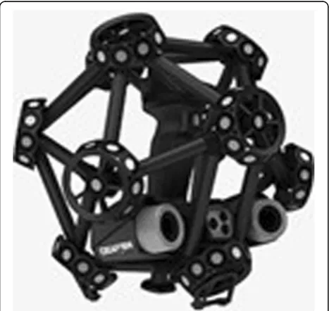
The equipment mainly used in this experiment is a hand-held laser 3D scanner, which mainly consists of the Creaform MatraSCAN 3D scanner probe and the
addition, the objects placed as the support in order to fa-cilitate the measurement, preparation of clean environ-ment, and the environmental light are needed. Finally, the preparation of tapes, pens, paper, and a U disk is a must to record the experimental data.
3.1.1.1 (1) How hand-held 3D laser scanner works
The sensor has two imaging probes for receiving signals. It is fixed with a triangular support and can adjust the angle to adapt to the received signal. There are two laser emission points on the probe. The offset to the object is received or reflected by other silver-white reflective points on the probe. After receiving, the laser-emitting point is symmetric to form a cross-laser range. The laser cross-sectional area based on the detection angle and the measurement distance is generally 70 mm × 70 mm. The camera sensor transmits the received signal to the host. The host uses the principle of triangulation based on the image distance, image point, depth distance, and so forth. The first point in this principle is that the emit-ted light beam is projecemit-ted on the object. The two points are the reflection points. The third point is the accepted camera probe. When it receives the signal of the reflec-tion point, it has two corners of the triangle and the dis-tance from the surface of the triangle to the surface of the object when it is launched. One of the three coordi-nates of the target can be obtained, one of which is spe-cific and is related to the launch angle and the coordinate direction setting. In the laser reflection movement process, there will be a difference in the angle formed by the movement, from which the other two are calculated. The coordinate point of the direction deter-mines the three-dimensional coordinates of the mea-sured object and feeds it back to the corresponding working machine, presenting a figure composed of a point cloud or a triangular face piece.
The working principle of the hand-held laser
three-dimensional scanner is to use the characteristics of the laser. The laser has less variation, less divergence, and almost no difference in the visible state. During op-eration, a continuous laser beam is emitted to the object to be measured by the laser emission source of the scan-ner head, and the beam is reflected after being touched by the object. The scanning probe has a certain number and angle of reflection points, and the camera is reflected back. The corresponding signal, through the reflected dis-tance of the received reflected laser light, calculates and records the reflected azimuth angle, transforming the measured object itself into coordinate points one after an-other. The final measured data is a set of massive stereo-digitized lattices, also known as point clouds, or a combination of triangular patches, which can be edited and output by special postforming software.
After the point cloud is scanned, the effects of various factors on the results during the scanning process are assessed, including the impact of the environment, the material of the scanning object itself, the obstacles in the transmission and reflection process, and so forth. These factors can cause a lot of noise. In the later period, this noise should be removed, and blank points that have not been scanned should be added to connect the point set to line and then connect the line to the surface again. After that, the surface is connected to the surface to make it a closed whole. After the closed whole, there will be corresponding loopholes, where the connection is not possible, for example. It requires simulation modeling to make up for gaps, and then it can be converted into cor-responding drawings for trial production and simulation applications.
3.1.1.2 (2) Instrument accuracy data The medium of laser scanner is changed from general white light to laser. The laser is easy to focus. The light has no obvi-ous change in size and thickness. When it encounters an object, it will not diffuse. The change is very small. The probe reflects the signal to the camera and receives the signal. Then the corresponding data is produced. Compared with the three-dimensional space, the pos-ition coordinate is formed. The way of point cloud ap-pears. The relatively popular laser scanner on the market is hand-held, industrial-grade because of the cost and direction of use problems application area is small, its hand-held laser three-dimensional scanner parameters are generally as Table1.
4 Process of 3D shape mapping of complex furniture experiment
“Complex furniture” is defined as a furniture that has a specially shaped surface, complex glyph, exquisite inter-ior structure, or large processing and production costs. The drawings that are necessary in the manufacturing process for“complex furniture”are not easy to produce, or a lot of effort needs to be spent in the process of drawing. But if we use the three-dimensional scanner technology, the 3D data of the complex furniture surface were obtained in a short time, and then the scanned data were converted into a common data format to simulate the scanned object model [7–10].
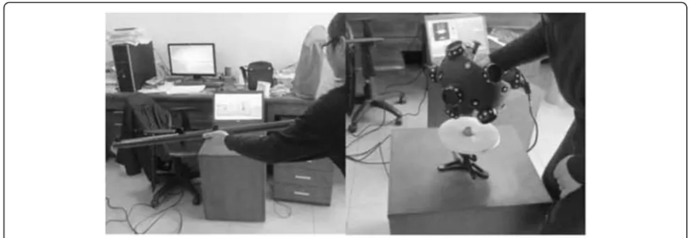
4.1 Assembly process of experimental instruments The process of the experiment begins with the assembly of the instrument. The scanner is installed in two moisture-proof, dust-proof, explosion-proof instrument boxes. The detailed image is shown in Figs.1,2and3.
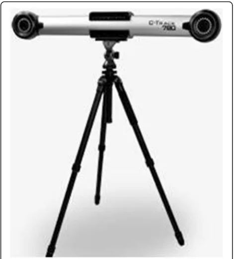
accuracy of the calibration, and the calibration period is normally about 10 days. First, we need to calibrate the C-Track 780 dual-camera sensor with a calibration point with a reflective point. The detailed image is shown in Figs.4and5.
4.2 The process of experimentation
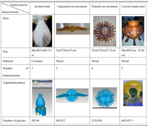
The first test is mainly to learn mapping, including the use of new instruments, the installation methods, and the test application equipment, so we chose an aroma bottle to do the test. Its material is porcelain, reflective, opaque, with a convex pattern. To facilitate scanning, a tea bucket with a diameter of 10 cm and a height of 20 cm was placed under the porcelain bottle. Click on the scan in the software toolbar. The laser-emitting switch of the probe is in the hand-held position and then scanning the bottle. When scanning cannot move too
fast, the signal reflection of fast-moving scanning cannot keep up, so holes and loopholes easily appear, and the holes and loopholes can be filled when scanning back, and some are difficult to fill in. Because the bottle can-not move, the entire surface below it is completely unscanned and needs to be repaired later. In order to scan out the bottle and the bottom completely, the tea tank supporting the bottle has to be scanned in as well. As the scanning probe moves, you can see the deep pur-ple dots on the screen, and the patches are formed as the scanning probe moves [11–14]. The detailed image is shown in Table1.
the constant adjustment of the angle. The position moved, and the edges of several scans were found to be inconsistent. During the second scan, we were very care-ful not to touch the object. At the same time, in order to complete the scan of the rounded edges, a large part of the surface of the cabinet had to be scanned, a lot of noise was formed, there were still many holes in some grooves, and the contoured groove edges were very
uneven. Give up this scan. During the third scan, a tea bucket was placed under the carved plate and scanned upward from below, so that there were complete upper and lower ends that could control the height of the scan results, which was very favorable for the accuracy of the scan. However, the wheels on the bottom of the cabinet were swept by the data line of the probe, and the pos-ition was moved and the scan failed. During the fourth scan, the unexpected problem was ruled out, and a height was found to be similar to that of a movable of-fice cabinet. But the surface area was smaller. Without wheels, the four corners would be flattened, the tea bucket would be placed on the table, and the carving board was placed on the tea bucket. The detailed image is shown in Table2.
The third test of the test object is an unpainted carved panel with scroll leaf decoration, commonly used in bed, sofa, doors, and other decorative furniture. The first is the selection of supports, flat chairs that are not easy to move, and a tea bucket. The sensor signal was not good, so we put the sculpture board up and measured to re-duce the area facing the sensor surface. It was found in the measurement that the carved board is the only bare board in the tested device, so the corners of the carved board are very clear, and the triangular patches cannot be completely filled in at the fine edges and corners, and there will be no broken holes that cannot be avoided. However, it does not have a special depth as a whole. From the point of view of the completion of the meas-urement and the speed of reaction for measuring the generated image, the material on the bare side is easier to measure than the lacquer engraving. From the image point of view, this sculpture’s symmetrical mirror image called each other. In order to ensure consistency, we turned it over and tested again. The detailed image is shown in Table2.
The fourth test of the detection object is no longer a single part of the engraving, but a whole carved stool. In this surveying and mapping, there are basically no major mistakes in the preliminary preparations. The carved stool is 26 cm high, so it was placed directly on the stool the first time. The problems during this time measurement are directly related to the difference between the whole and part of the measurement, so that the content to be repaired is very large. The biggest reason that caused this measurement to start from a new position was that the stool was not placed in the right place. One was too low, and the other was too normal. When the probe was scan-ning the stool, the obstacle was very big. So, the scanned surface is not very satisfactory. On the second scan, we put another small stool on the original chair. This time the goal is one-fifth of the stool, and one-fifth of the scans are relatively good. However, because of the depth prob-lem, all the insides of the legs cannot be completely swept Fig. 1MatraSCAN three-dimensional scanner probe
away. The completion of the entire target cannot rely solely on positive surveying and mapping, and negative mapping is also needed. We need to drag them into the same interface to modify them to be complete. However, in practice, owing to the large number of patches, we can only do our best to delete and repair them, and then ex-tract the necessary points and then drag them in again. The detailed image is shown in Table2.
5 Results and discussions of the experiment 5.1 Analysis of result
After contrasting several experiments, we summarized in Table3 the reasons for the failure of the operation in using a hand-held laser scanner [15–18]. From the table above, we can see that the failure points can be classified into two types of factors: one is the dual-camera sensor signal reception problems, and the other is the inappro-priate support surface.
In view of the above problems, I summarize the points of attention of using the laser scanner in the surveying and mapping:
1. The limitations of laser scanners in depth are significant; the best way is to remove furniture parts, scan, and expose more surfaces.
2. Scanning for object placement to choose to be careful, not to the surface as little as possible with the pattern or different shapes, placing a high
degree of moderate, reducing the impact on the signal transmission, convenient measurement. The platform surface area of the object is not to exceed the scope of the contact.
3. Late data processing not to focus on the overall repair; the corresponding skills can be used to reduce the amount of repair work, to pay attention to the order of processing to ensure that the model is complete.
5.2 High accuracy experiment suggestion induction Summarizing the above-mentioned problems, and com-paring the molding results in the later stage of the trial data collection, the furniture mapping was carried out on the armless hand-held laser three-dimensional scanner using the Creaform MatraSCAN 3D scanner probe and the C-Track 780 dual-camera sensor system. The follow-ing aspects can be hand-held with high precision [19,20].
1. In terms of instrumentation, a new version of the probe has emerged, which remains hollow on the basis of the original solid left behind by the skeleton as shown in Fig.6, effectively reducing its weight and signal occlusion capabilities. You can try to use a robotic arm. Compared with human instability, the robotic arm has excellent capabilities in terms of rotation angle and speed.
Fig. 3Explosion-proof instrument box
2. In the operation of surveying and mapping, to choose suitable support for the object to be measured, the surface area is the same as the contact surface of the object to be measured, preferably a combination of a fine column and a table, and it cannot be wheeled and stable. There is a certain weight. Handle excess lines to prevent tripping during surveying. When placing an object, observe the object first. The measured area on the bad signal surface should be as small as possible. Symmetrical or mirror image should not have a large amount of greed for the whole scan. This can prevent the main part from being placed in a relatively good signal position.
3. Owing to the limitations of instrument
measurement depth, obviously not suitable for the structure is too complex, the structure is not only complex when the mapping is limited, there is also a clear disadvantage in the post-processing, from the scanned surface into a body, without thickening, The generated surfaces are all complemented by
sweeping lines, such as the sculptured stool in the experiment. In the middle, no matter from which aspect the inside of the leg is not accessible, the raised stool is. The later software complement map is based on the edge curve, so it does not make up. Single-piece furniture components, carved panels, and other effects are good, it is recommended that complex furniture be disassembled to scan. 4. From the aspect of manpower, because this type of
scan can be terminated and started at any time, given the manpower consumed, it is recommended that this experiment be carried out by multiple people in turn, the weight of the probe alone is still very laborious, the accuracy of the experiment and the accuracy of the test have an effect.
5. Pay attention to some application skills in the processing of late-stage data. If there are too many points, remember to simplify and facilitate the fluency and accuracy of processing. The scanned data do not have to be scanned nearly perfect to reduce the subsequent workload. Because of some Fig. 5C-Track 780 dual-camera sensor
Table 2Hand-held laser scanner parameter table
Light source 6-Line laser array, class II (human eye safety) Transmission mode USB3.0
Scanning rate 240,000 s Working temperature −10 to 40 °C
Scanning area 230 mm × 250 mm Working humidity 10–90%
Resolving power 0.100 mm
Measurement accuracy ≤0.03 mm
Working distance 300 mm
Depth of field 250 mm
Measuring range (Object size) 0.1–6 (meter), extensible
Data-compatible software
Geomagic Solutions (3D Systems, Rock Hill, SC, USA); InnovMetric Software (PolyWorks, Québec, QC, Canada); CATIA V5, SolidWorks (Dassault Systèmes, Charlotte, NC, USA); Pro/ENGINEER (PTC, Shanghai, China); NX, Solid Edge
irresistible factors, the uneven or damaged surface cannot be completely changed after multiple scans. Therefore, a part of it can be based on the principle of symmetry or mirror; that is, the whole area can be adjusted by adjusting this part. On the part of the signal is good, but also suitable for scanning.
6 Conclusions
Through this experiment, we detected and studied how to improve the hand-held laser scanner method. However, we must continue to promote the development of 3D scanning technology and integrate advanced technology into furniture mapping, thus making modern advanced manufacturing technology spread and develop better. Through modern mapping technology, we can speed up the progress and the accuracy of mapping complex furni-ture. Using surveying and mapping methods, we can help retain a large number of precious structures or patterns of
drawings and laying a technology foundation for contrib-uting furniture digital library system with high quality and commercial application value, which is good for cultural transmission and in line with the development trend of environmental protection through green and low-carbon industry.
Abbreviations 3D:Three-dimensional
Acknowledgements
The authors thank the editor and anonymous reviewers for their helpful comments and valuable suggestions.
Funding
This work was supported in part by a project funded by National Key Technologies R&D Program of China (2017YFD0601104), Jiangsu Co-Innovation Center of Efficient Processing and Utilization of Forest Resources.
Availability of data and materials
We can provide the data.
Authors’contributions
All authors took part in discussion of the work described in this paper. ZC wrote the first version of the paper. YM did part of the experiments described in this paper. ZT revised the paper in different versions of it. All authors read and approved the final manuscript.
About the authors
Chengmin Zhou received a BE degree in Industrial Design from Jiangnan University, Wuxi, China, in 2000; an MA degree in Art and Design from Jiangnan University, Wuxi, China, in 2003; and has been a Ph.D. candidate in furniture design and engineering at Nanjing Forestry University, Nanjing, China, from 2016. In 2003, she joined Nanjing Forestry University, Nanjing, China. From 2003 to 2011, she was a lecturer in the College of Furniture and Industrial Design, Nanjing Forestry University. From 2012 to the present, she has been an associate professor of the College of Furnishing and Industrial Design, Nanjing Forestry University. From 2014 to 2015, she joined the Research Center for Furniture, Buckinghamshire New University, London, UK, as a visiting scholar. Her current research interests include furniture design of cultural heritage, informatization and datalization of furniture design, furniture design industrialization and engineering, design technology, and future innovation design trends. She also is an MA instructor, Deputy Editor-in-Chief ofFurniture
magazine, Design Director of Classical Furniture and Mahogany Craft Institute, a member of the Asian Design Culture Society, and a member of the Jiangsu Industrial Design Association. She has published 40 journal articles, authorized 40 patents, obtained 18 teaching awards, carried out about 30 research projects, and designed hundreds of furniture products.
Contact: [email protected]
Mengnan Yu is currently studying for her master’s degree in Industrial Design Engineering at Nanjing Forestry University, Nanjing, China. Her
Fig. 6Improved probe effect picture
Table 3Comparison of experimental failure causes
Objects Measuring times Operational error
Aroma bottle 1 The first attempt was affected mainly by the dual-camera sensor
Unpainted carved panels
4 1. The cabinet used to keep the object stable was not good. Objects can change position easily.
2. The measured object height is not appropriate; the edge is difficult to clearly sweep to.
3. The surface on which the object to be measured is placed is too large, and this affects the scanning of the partial scan angle.
Painted carved panels 2 Support area is greater than the measured object, which leads to too many useless data points.
Carved round stool 3 1. Wrong position, wrong height, and the support surface is too large.
research interests focus on digital image and computer vision, product design, and graphic design.
Contact:[email protected]
Tao Zhou is currently studying for his master’s degree in Industrial Design Engineering at Nanjing Forestry University, Nanjing, China, His research interests focus on furniture design and engineering.
Contact:[email protected]
Ethics approval and consent to participate
Approved.
Consent for publication
Approved.
Competing interests
The authors declare that they have no competing interests.
Publisher’s Note
Springer Nature remains neutral with regard to jurisdictional claims in published maps and institutional affiliations.
Received: 11 April 2018 Accepted: 19 July 2018
References
1. DH Zhen, Analysis of three dimensional laser scanner and its measurement error. Eng. Surveying Engineering.8(2), 32–34 (2005)
2. BM Xu,Furniture Design(China Light Industry Press, Beijing, 2000) 3. R Zhuang, YH Wu,Furniture and Furnishings, 2nd edn. (China Building
Industry Press, Beijing, 2003)
4. G Jin,Pattern Recognition and Intelligent System(Huazhong University of Science and Technology, Hubei, China, 2002)
5. GH Zhang, Deformation monitoring based on 3D laser scanner. Comput Eng Appl.1(1), 96–97 (2006)
6. CM Zhou, ZH Wu, JF Lv, C Dong, Comparison of 3D scanning and manual mapping of Chinese traditional furniture. J Jiangnan University.
10(5), 518–522 (2011)
7. M Gao, RH Zhou, Research on the reconstruction and innovation design of antique furniture products. Automated manufacturing.33(10), 150–152 (2011) 8. Y Zhang,Analysis on the traditional methods and modern techniques of
ancient building surveying and mapping(Taiyuan University of Technology, Shanxi, China, 2014)
9. X Du,Surveying and mapping based on industrial building heritage(Tianjin University, Tianjin, China, 2013)
10. S Chen,Study on process and analysis of NC machining process for furniture engraving parts(Nanjing Forestry University, Jiangsu, China, 2007) 11. RQ Zhang, QT Huang, S Li, Y Qin, Application of reverse engineering
method in the design of complex part surface. Furniture36(1), 8–12 (2015) 12. RQ Zhang, Application and research of reverse engineering in classical
furniture protection. J High-tech Ind Dev.30(1), 101–103 (2013) 13. SL Yu, ZY Wang, Visual design of surface modeling in reverse engineering.
For M and W. E.30(12), 12–13 (2006)
14. FR Mao, L Wang, Three-dimensional laser scanning measurement technology. Aero. Mechanical Design25(2), 86–90 (2005)
15. Q Feng, Q Ren, W Li, 3D imaging technology in InSpeck imaging system [in Chinese]. Laser Optoelectron. Progr.43(4), 52 (2006)
16. PG Horvath, Z Kovacs, L Denes, Ergonomic design using quality function deployment and design of experiments. For. Products J.63(7), 257–262 (2013) 17. E Loučanová, J Parobek, H Paluš, Identifikácia požiadaviek slovenských
zákazníkov na úložný nábytok na základe modelu kanoacta facultatis xylologiae zvolen. Zvolen, Slovakia: Technická univerzita vo Zvolene, 56(1), 109–117 (2014).
18. V Barnekov, O Suchsland, R Nedeltchev, Live-sawing hardwood logs for furniture dimension production. For. Products J.48(2), 34–39 (1998) 19. OC Amans, W Beiping, YY Ziggah, AO Daniel, The need for 3D laser
scanning documentation for select Nigeria cultural heritage sites. Eur. Scie. J.9(24), 32–34 (2013)