Automatic Brix Estimation in Massecuite
using LabVIEW
P.Dharani1, V.R.Gokulraj2, K.N.Baluprithviraj3
UG Student, Department of EIE, Kongu Engineering College, Perundurai, Tamilnadu, India1,2 Assistant Professor, Department of EIE, Kongu Engineering College, Perundurai, Tamilnadu, India3
ABSTRACT: In Sugar Industry, Brix is the amount of sucrose content present in the massecuite. Massecuite is the suspension of sugar crystals which is the concentrated cane juice obtained after boiling. Degree Brix is the measure of the concentration of dissolved solids in the solution. Based on the brix value in massecuite, the output of the sugar crystal is obtained. Hence the brix content should be maintained around 65˚ brix. If the brix value is lower than the
desired value, steam has to be passed into the massecuite. Similarly hot water has to be passed if the brix value is higher than the desired value. Currently in the sugar industry, brix sensor is used to measure the brix content and the respective control valves are operated manually to maintain the brix context for every 1 hour. In this paper, the brix is measured and the valve controls are done automatically by interfacing NI USB-6009 DAQ using LabVIEW. By this method there will be a continuous monitoring of brix content and hence the quality of sugar crystal is ensured.
KEYWORDS: Brix Sensor, Helical Type Gear Motor, Solenoid Valve, Data Acquisition
I.INTRODUCTION
Sakthi Sugars Limited is one of the largest producers of white crystal sugar in the country accounting for a capacity of 19,000 Tons of Cane crush per Day (TCD). The sugar produced is at par with International Standards with very low NSR (Non Soluble Residue) value of less than 20 ppm. Unit-4 in Aval poondurai via Erode has both sugar and power production. Sugar Factory consists of the following five main stations:Mill House, Boiler House, Power House, Clarification and Evaporation House, Boiler and Curing House. Mill house is the cane crushing unit which consists of cane carrier, cane cutter having cutting knives, bagasse carrier and conveyor. Cane feeding to the cane carrier is done by unloaders and feeder table. As the cane carrier moves, the cane kicker evens out cane load in the cane carrier and then two sets of cane knives cut the cane into small pieces. This process of cane cutting is called cane preparation. These cane pieces then pass through different mills and the juice is extracted. Boiler generates steam by burning the bagasse. The steam is used in powerhouse, boiling house, curing house. The steam required by the sulphitation process varies from 42 - 45 % on cane crushed per hour.
The juice extracted by the mills is measured by juice flow system. The measured juice is heated in juice heater in two stages. First the juice is heated by the vapours from third and fourth bodies of evaporator in different heaters. This heating is called primary heating. The heated juice is treated with milk of lime and sulphur-di-oxide to coagulate maximum impurities and sent for secondary heating. The secondary heating is done with vapours from second body of evaporator and vapours from the first body or exhaust steam. The treated juice is passed to clarifier where in clear juice is removed from the top and settled mud at the bottom is separated. Sulphited syrup is taken to pan floor for making sugar crystal. Three massecuites boiling systems are normally adopted in which A, B and C Massecuites are boiled. A-massecuite is formed by boiling syrup, sugar melt, A-light molasses and on B-single cured sugar used as seed. This A-Massecuite is boiled till it attains the required size of sugar crystal and it is dropped into crystallizers and cooled. After exhaustion of sugar in solution, the A massecuite is passed on to the centrifugal for separating sugar crystals from the massecuite. The separated A-sugar is bagged after drying. A-Light and A-Heavy molasses are pumped to pan floor and are used for making A and B-Massecuite respectively.
II.PROCESS ANALYSIS
II.A. PROBLEM DEFINITION
One of the major problems faced by the sugar industry is the maintaining of sugar quality. Brix content in the massecuite plays a major role in sugar industry. Brix content can be maintained by regulating the flow of steam and hot water into the massecuite.
II.B. EXISTING SYSTEM
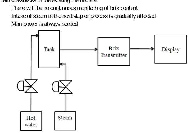
In the existing method shown in Figure 1, the person will take the sample of syrup from the flow and measure the brix value using brix sensor. If the measured brix value is high, the person will open the hot water into it which will loosen the syrup. Similarly if the measured brix value is low, the person will open the steam into the massecuite. Every 1 hour, the person should check the brix value to maintain the sugar quality.
The main drawbacks in the existing method are
There will be no continuous monitoring of brix content
Intake of steam in the next step of process is gradually affected
Man power is always needed
Fig. 1: Existing Brix Monitoring Method in Industry
One degree Brix is 1 gram of sucrose in 100 grams of solution and it represents the strength of the solution as percentage by mass. The brix is measured by Brix Sensor in the industry. The specification of the Brix Sensor is used in the industry is shown in Table 1.
Table 1 Brix Sensor Specifications
Parameter Specifications
Sensing range Brix: 0.0 to 80.0%
Temperature : 5 to 100゚C / 41 to 212゚F Resolution Brix : 0.01 or 0.1%
Ambient Temperature 5 to 40゚ C
III. DESIGN OF PROPOSED MODEL
III.A. PROPOSED MODEL
There will be continuous flow of massecuite in the process tank from the main sugarcane juice tank whose brix value should be maintained. The main objective of this paper is to maintain the brix value continuously. If the value is high, hot water has to be passed into the massecuite and if its value is low, steam has to be passed into massecuite. The brix value is estimated using the DC gear motor. According to the brix content, the voltage will change within this range. This motor is connected to LabVIEW for continuous monitoring of brix. The interfacing of motor to LabVIEW is done using the DAQ card NI USB-6009.
The set value of brix is given to it. If the measured value is greater than the set value, it will open the solenoid valve of the hot water and if it is lesser than the set value, it will open the drain valve. Suppose if the level of massecuite is below the set level in the process tank, the valve of sugarcane juice tank will open to maintain the level of massecuite in the process tank. Hence by this paper, there is a continuous monitoring of brix content in process tank. The block diagram of proposed model is shown in Figure 2.
Fig. 2: Block Diagram of Proposed Model
The voltage sensed from the motor corresponds to the specific gravity of the massecuite in the process tank. From the specific gravity, the brix valve can be computed using the formula,
Degree Brix = 231.61*(S-0.9977) Where S=specific gravity of the solution If the measured value is S=1.28, then Degree Brix = 231.61*(1.28-0.9977) = 65.38
= 65̊ Brix (approx.)
IV.HARDWARE DESCRIPTION
IV.A. MOTOR DRIVER
Table 2 Helical Type Gear Motor Specifications
Parameter Specifications
Output rpm 100 at 12V Voltage 6V to 12V Power 180W Shaft diameter 12mm
Shaft length 55mm, 4mm key slot for good coupling Gear Assembly Worm
Brush type Carbon
IV.B. RELAY
A relay is an electrically operated switch. Current flowing through the coil of the relay creates a magnetic field which attracts a lever and changes the switch contacts. The coil current can be ON or OFF. So relays have two switch positions and they are double throw switches. Relay driver circuit consists of resistor, Zener diode, NPN transistor as show in Figure 3.
Fig: 3. Circuit Diagram of Relay
Resistor is used to protect the transistor from excess supply. Transistor needs 5V supply to operate and the signal passes to the magnetic coil, produce EMF. Diode is connected across the coil to avoid back EMF.
IV.C. SOLENOID VALVE
created, causing the plunger inside the coil to move. Depending on the design of the valve, the plunger will either open or close the valve. When electrical current is removed from the coil, the valve will return to its de-energized state.
In this paper, three solenoid valves are used. The first solenoid valve is used for filling the process tank from the sugar juice tank. The second solenoid valve is used for opening the hot water into the process tank if the brix valve is low and finally the third solenoid valve is used to pass the steam into the process tank if the brix value is high.
IV.D.DATA ACQUISITION
Data Acquisition (DAQ) is the process of measuring an electrical or physical phenomenon such as voltage, current, temperature, pressure or sound with a computer. A DAQ system consists of sensors, DAQ measurement hardware and a computer with programmable software.
Data acquisition hardware acts as the interface between the computer and the outside world. It primarily functions as a device that digitizes incoming analog signals so that the computer can interpret them.
The National Instruments USB-6009 devices provide eight single-ended Analog Input (AI) channels, two Analog Output (AO) Channels, 12 DIO channels and a 32-bit counter with a full-speed USB interface.
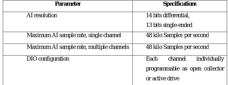
The important specification of NI USB-6009 for interfacing the motor with the LabVIEW used in this paper is shown in Table 3
Table 3 NI USB-6009 Specifications
Parameter Specifications
AI resolution 14 bits differential, 13 bits single-ended Maximum AI sample rate, single channel 48 kilo Samples per second Maximum AI sample rate, multiple channels 48 kilo Samples per second DIO configuration Each channel individually
programmable as open collector or active drive
The NI USB-6009 features a USB connector for full-speed USB interface. Strain relief for the USB cable can be provided by threading a zip tie through the USB cable strain relief ring and tightening around a looped USB cable.
IV.E Analog Input Circuitry
The NI USB-6009 has eight analog input channels that can use for four differential analog input measurements or eight single-ended analog input measurements.
The main blocks featured in the NI USB-6009 analog input circuitry are shown in Figure 4 as follows:
Fig:4. Analog Input Circuitry of NI USB-6009
V. SOFTWARE DESCRIPTION
V.A LabVIEW
Laboratory Virtual Instrument Engineering Workbench (LabVIEW) is a system-design platform and development environment for a visual programming language from National Instruments. It is a tool to solve many problems faster and more effectively with the capacity to evolve to meet the future challenges. LabVIEW offers unprecedented integration with all measurement hardware, existing legacy software and IP while capitalizing on the latest computing technologies.
V.B SETTING UP THE NI USB-6009
Install the application software
Install NI-DAQmx. The documentation for NI-DAQmx is available after installation from Start, All Programs, National Instruments, NI-DAQmx
Install the 16-position screw terminal plugs by inserting them into the connector jacks
Affix the provided signal labels to the screw terminal connector plugs and choose labels with pin numbers, signal names or blank labels
Plug one end of the USB cable into the NI USB-6009 and the other end into an available USB port on the computer
Expand My System Devices and Interfaces and verify that the NI USB-6009 is listed. If the device does not appear, press <F5> to refresh the view in MAX
Run a Test Panel in MAX by right-clicking NI USB-6009 and selecting test Panels
Click Start to test the device functions or Help for operating instructions. Click Close to exit the test panel
V. RESULTS AND DISCUSSION
Table 4 Process Executed in the Proposed Method
S.No. Brix value Solenoid valve 1 (sugar
juice tank)
Solenoid valve 2 (hot water)
Solenoid valve 3 (steam supply)
1 62 OFF ON OFF
2 65 OFF OFF OFF
3 68 ON OFF ON
The brix is controlled as shown in Table 4. Thus the amount of hot air and steam blown into the massecuite tank is controlled according to the brix content in it. Thus more accuracy can be obtained from this paper. Due to continuous monitoring of brix content, any errors occurring in manual adjustment of flow in steam and hot water into the massecuite is minimised.
Fig:6. Electrical Setup
VI.CONCLUSION
Brix Automation in Massecuite finds wider application in all sugar industries for maintaining the quality of sugar. This hardware setup is simple and cost effective and this software is user friendly. It improves the quality of sugar and enables continuous monitoring of brix without manual intervention. It enhances the steam consumption flow and hence supports the next processes effectively
.
REFERENCES
[1] Bela G Liptak, “Instrument Engineers Handbook (Measurement),” Butterworth-Heinemann Ltd, Oxford, 1995. [2] Bielmann, V Gillinan, J Perkins, N R Skidmore, “An Evaluation of Brix Instruments”, Mascot Publisher, Austraila, 2003. [3] George Stephanopoulos, “Chemical Process Control”, Prentice Hall of India, New Delhi, 1990.
[4] H Ito, “Potential of near Infrared Spectroscopy for Estimation of Brix”, Fourth Edition, Gefen Publishing House, United States, 2008. [5] M V Kiran, A Suresh, K Sudha Rani, “Novel Energy Management System in Suger Industry at Cogeneration Plant”, Computational
Intelligence and Computation Research (ICCIC),IEEE International Conference,pp. 1-4 Coimbatore 2014.
[6] S Crisafulli, R D Sperice, “Surge Tank Control in a Cane Raw Suger Factory”,Control Applications, Sencond IEEE Conference, Vancouver, BC, 1993.
[7] S Lissane Elhaq, F Giri, H Unbehauen, “Experimental Identification of five-effect Evaporator in Sugar Industry”,IEEE Conference, pp.3532-3536,1997