Modeling of Single-Phase To Three-Phase Drive System
CH. Prashathi M.Tech, PEED Ravula Srikanth Asst. Professor, EEE
Sahasra College Of Engineering For Women, Warangal
ABSTRACT:This paper presents single-phase to three-phase with dc-link converters with parallel rectifier and series inverter forreduction in the input current and reduction of the output voltage processed by the rectifier circuit and inverter circuitrespectively. In this paper we proposed better solution for single phase to three phase drive system by employing 2parallel single phase rectifier stages, a 3-phase inverter stage. Parallel converters can be used to improve the powercapability, reliability, efficiency and redundancy. An isolation transformer is not used for the reduction of circulatingcurrents among different converter stages. It is an important objective in the system design. The complete comparisonbetween the comprehensive model of proposed converter and standard configurations will be presented in this work.Simulation of this model will be carried out by using MATLAB/ Simulink.
KEYWORDS-AC-DC-AC power converter, drive system, parallel Converter, Fault Identification System(FIS).
I. INTRODUCTION
Most power conversion applications consist of an AC-to-DCconversion stage immediately following the AC source. TheDC output obtained after rectification is subsequently usedfor further stages. Thereby an ac to dc converter hasbecome an integral part of mostly all the electronicequipments. Mainly, it is used as an interface betweenutility and most of the power electronic equipments[1].These electronic equipments also form a major part of loadon the utility. Two factors that provide a quantitativemeasure of the power quality in an electrical system arePower Factor (PF) and Total Harmonic Distortion (THD).The amount of useful power being consumed by anelectrical system is predominantly decided by the PF of thesystem.
Generally, to convert line frequency ac to dc, a linefrequency diode bridge rectifier is used. To reduce theripple in the dc output voltage, a suitable filter capacitorand/or an inductor is used at the rectifier output[2]-[3]. Butdue to these reactive components, the current drawn by thisconverter is peaky in nature, very much differed from asinusoidal shape. This input current is rich in lower orderharmonics. Also, as power electronics equipments areincreasingly being used in power conversion, they inject loworder harmonics into the utility. Due to the presence ofthese harmonics, the total harmonic distortion is high whenso many converters are put together in a huge electronicsystem. Additionally, the input power factor becomespoorer. Due to the disadvantages associated with lowpower factor and harmonics, utilities enforces (in somecountries) harmonic standards and guidelines which willlimit the amount of current distortion allowed into the utility.Looking into the serious effects generated by conventionalconverters, the simple diode rectifiers should not be used.There is a need to achieve rectification at close to unitypower factor and low input current distortion.
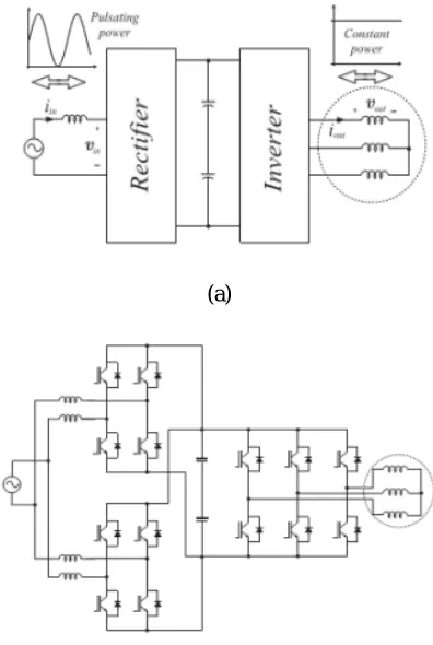
Fig. 1.Conventional single-phase to three-phase drive system.
This converter is denoted here as conventionaltopology. In this paper, a single-phase to three-phasedrive system composed of two parallel single-phaserectifiers and a three-phase inverter is proposed, asshown in Fig. 2.
Fig.2. Proposed single-phase to three-phase drivesystem.
The proposed system is conceived to operate where the single-phase utility grid is the unique option available. Compared to the conventional topology, the proposed system permits: to reduce the rectifier switch currents; the total harmonic distortion (THD) of the grid cur-rent with same switching frequency or the switching frequency with same THD of the grid current; and to increase the fault tolerance characteristics. In addition, the losses of the proposed system may be lower than that of the conventional counterpart.
The aforementioned benefits justify the initial investment of the proposed system, due to the increase of number of switches.
Fig 3. Shows the single-phase to three-phase powerconversion with parallel configuration.Another importantcharacteristic observed in the single-phase to three-phasepower converters that also has been considered in thispaper is the irregular distribution of power losses amongthe switches of the converter, as observed in Fig. 4.It means that, for a 600 V 50A class of insulated gatebipolar transistor (IGBT), 63% of the total lossesmeasured in the single-phase to three-phase converter isconcentrated in the rectifier circuit, while the rest 37% isobserved in the inverter circuit. With those numbers, it ispossible to measure the stress by switch, which means thateach rectifier switch is responsible for 15.7% of the totalconverter losses, while each inverter switch is responsiblefor only 6.1%. The loss per switch gives an importantparameter regarding the possibilities of failures in thepower converters.
(b)
(c)
Fig. 3. Single-phase to three-phase power conversion. (a)Type of power processed by rectifier and inverter
circuits.(b) Solution employed in [15]. (c) Solution employed in[16]
Fig. 4. Converter power losses distribution in both rectifier and inverter units:63% in the rectifier circuit and 37% in the inverter one. Power losses in eachswitch of the rectifier (15.7%) and inverter (6.1%).
II. SYSTEM MODEL
This section will present the model of the proposedconfiguration. Such a configuration is constituted by a where p = d/dt and symbols like r and l represent theresistances and inductances of the input inductors. Thecirculating current io can be defined from ia and i’ a or iband i’b i.e.
= − =− +
= −[ + + ( + ) ] + ( + )
= −[ + + ( + ) ] + ( + )
=−[ ′+ + ( ′+ ) ]
−( − + ( + ) ] + [ + + ( + ) ]
Fig. 5.Proposedsingle-phase to three-phase drive system.
To avoid the circulating current, the following threeapproaches are used commonly
i. Isolation. In this approach, the overall parallel systemis bulky and costly because of additional powersupplies or the ac line-frequency transformer.
ii. High impedance. They cannot prevent a lowfrequency circulating current.
iii. Synchronized control. This approach is not suitablefor modular converter design. When more convertersare in parallel, the system becomes very complicatedto design and control.
In this proposed method the system is designed to reducethe circulating current (Io). From fig.5.the
− = −( + ) −( + )
− = −( + ) −( + )
− = ( + ) −( + )
In this ideal case, the circulating current can be reduced to zero imposing
= + − − = 0
when = 0 then = and = and the system model reduced to the model given by
+
2 = −2( + ′ )
+
2 = −2( ′+ ′ ) = 2( ′+ ′ )
= +
2 = −( ′+ ′ )
−
2 = −2( ′+ ′ ) ′
−
2 = −2( ′+ ′ ) ′ = −2( + ′ ) = −2( ′+ ′ )
III. CONTROL STRATEGY
The gating signals are obtained by comparing polevoltages with one (vt1), two (vt1 and vt2) or more highfrequency triangular carrier signals. In the case of doublecarrier approach, the phase shift of the two triangularcarrier signals (vt1 and vt2) is 1800. The parameter µchanges the place of the voltage pulses related to vaand vb.When vx* = vx*min (µ = 0)
orvx* = vx*max (µ = 1) areselected, the pulses are
placed in the beginning or in theend of half period (Ts) of the control block diagram of Fig.2, highlighting the control of the rectifier. To control thedc-link voltage and to guarantee the grid power factorclose to one. Additionally, the circulating current io in therectifier of the proposed system needs to be controlled.
In this way, the dc-link voltage vc is adjusted to itsreference value v c* using the controller Rc, which
is astandard PI type controller. This controller provides theamplitude of the reference grid current Is*. To controlpower factor and harmonics in the grid
side, theinstantaneous reference current Is* must be
synchronizedwith voltage e.g., as given in the voltage-oriented control(VOC) for three-phase system. This is obtained via blocksGe-ig, based on a
PLL scheme Fig 6. The referencecurrents I a*and ib* are obtained by making ia* = ib* = Is*/2, which means
that each rectifier receives half of the gridcurrent. The control of the rectifier currents isimplemented using the controllers indicated by blocks Raand Rb.
These current controllers define the inputreference voltages va*and vb*. The homo polar current
ismeasured (io) and compared to its reference (io* =
0). Theerror is the input of PI controller Ro, that determines thevoltage vo*. The motor there-phase
voltages are suppliedfrom the inverter (VSI). Block VSI-Ctr indicates theinverter and its control. The control system is composed ofthe PWM command and a torque/flux control strategy(e.g., field-oriented control or volts/hertz control)
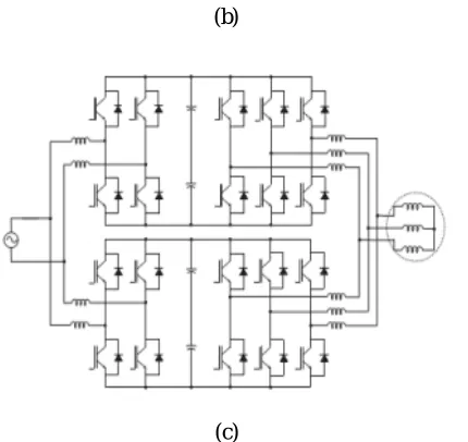
Fig. 6. Control block diagram
IV. SIMULATION RESULTS
μF, and input inductor filterswith resistance and inductance given respectively by 0.1Ωand 2.6 mH. The load power was of 5 kVA.
Fig 7 MATALB/SIMULINK diagram of proposed
system
Fig 8 voltage and current of the grid,
Fig 9 input current of the converter 1
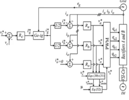
Fig 10 input current of the converter 2
Fig 11 circulating current
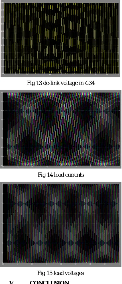
Fig 13 dc-link voltage in C34
Fig 14 load currents
Fig 15 load voltages
V. CONCLUSION
A single-phase to three-phase drive system composed of two parallel single-phase rectifiers, a three-phase inverter and an induction motor was proposed. The systemcombines two parallel rectifiers without the use oftransformers. The system model and the control strategy,including the PWM technique, have been developed. Thecomplete comparison between the
proposed and standardconfigurations has been carried out in this paper.Compared to the conventional topology, the proposedsystem permits to reduce the rectifier switch currents, theTHD of the grid current with same switching frequency orthe switching frequency with same THD of the gridcurrent and to increase the fault tolerance characteristics.In addition, the losses of the proposed system may belower than that of the conventional counterpart. The initialinvestment of the proposed system (due to high number ofsemiconductor devices) cannot be considered a drawback,especially considering the scenario where the citedadvantages justify such initial investment.
REFERENCES
[1]. Bhim Singh, Sanjeev Singh, Ambrish Chandra, andKamal Al-Haddad, “ Comprehensive Study ofSingle-Phase AC-DC Power Factor CorrectedConverters With High-Frequency Isolation”
, IEEETRANSACTIONS ON
INDUSTRIALINFORMATICS, VOL. 7, NO. 4, NOVEMBER2011, pp 540-556
[2]. Bhim Singh and Ganesh DuttChaturvedi“Analysis, Design, Modeling, Simulation andDevelopment of Single-Switch AC-DC Convertersfor Power Factor and Efficiency Improvement”,Journal of Power Electronics, Vol. 8, No.1, January2008, pp51-59.
[3]. Gerry Moschopoulos and Praveen Jain, “SinglePhase Single-Stage Power-Factor-CorrectedConverter Topologies”, IEEE Transactions OnIndustrial Electronics, Vol. 52, No.1, February2005, pp23-35.
[4] M. Liserre, ―Dr. Bimal K. Bose: A reference for generations[editor’s column], IEEE Ind. Electron. Mag., vol. 3, no. 2, pp.2–5, Jun. 2009.
[6] F. W. Gutzwiller, ―Thyristors and rectifier diodes-thesemiconductor workhorses, IEEE Spectrum, vol. 4, no. 8, pp.102–111, Aug. 1967.
[7] A. Elasser, M. H. Kheraluwala, M. Ghezzo, R. L. Steigerwald,N. A. Evers, J. Kretchmer, and T. P.
Chow, ―A comparativeevaluation of new silicon
carbide diodes and state-of-the-artsilicon diodes for power electronic applications, IEEE Trans.Indust. Appl., vol. 39, no. 4, pp. 915– 921, Jul. /Aug. 2003.
[8] M.-K. Nguyen, Y.-G.Jung, and Y.-C. Lim, ―Single-phase AC–AC converter based on quasi-z-source topology, IEEE Trans.Power Electron., vol. 25, no. 8, pp. 2200–2210, Aug. 2010.
[9] M.-K. Nguyen, Y. cheol Lim, and Y.-J. Kim, ―A modifiedsingle-phase quasi-z-source AC–AC converter, IEEE Trans.Power Electron., vol. 27, no. 1, pp. 201–210, Jan. 2012.
[10] B. Saint, ―Rural distribution system planning using smart gridtechnologies, in Proc. Rural Electric Power Conf., Apr. 2009,pp. B3-1–B3-8.
[11] A. R. C. de Lima Montenegro Duarte, U. H. Bezerra, M. E. deLima Tostes, and G. N. da Rocha Filho, ―Alternative energysources in the Amazon, IEEE Power Energy Mag., vol. 5, no. 1,pp. 51–57, Jan./Feb. 2007.
[12] X. Wang, H. Zhong, Y. Yang, and X. Mu, ―Study of a novelenergy efficient single-phase induction motor with three seriesconnected windings and two capacitors, IEEE Trans. EnergyConvers., vol. 25, no. 2, pp. 433– 440, Jun. 2010.
[13] M. Khan, I. Husain, and Y. Sozer, ―Integrated electric motordrive and power electronics for bidirectional power flowbetween the electric vehicle and DC or AC grid, IEEE Trans.Power Electron., vol. 28, no. 12, pp. 5774–5783, Dec. 2013.
[14] Y.-S. Lai, W.-T.Lee, Y.-K.Lin, and J.-F. Tsai, ―Integratedinverter/converter circuit and control technique of motor driveswith dual mode control for
EV/HEV applications, IEEE Trans.Power Electron., vol. 29, no. 3, pp. 1358–1365, Mar. 2014.
[15] C. B. Jacobina, E. C. dos Santos, Jr, N. Rocha, and E. L. LopesFabricio,―Single-phase to three-phase drive system using twoparallel single-three-phase rectifiers, IEEE Trans. Power Electron.,vol. 25, no. 5, pp. 1285–1295, May 2010.
Authors:
Ch. Prashathi pursing M.Tech in PEED from sahasra college of engineering for women, warangal.