Soft Switching Three Phase Push-Pull DC-DC
Converter
Jafar Ali,
K.Prakash
Dept. of EEE, Bharath University, Chennai, Chennai, Tamil Nadu, India
Associate Professor, Dept. of EEE, Bharath University, Chennai, Tamil Nadu, India
ABSTRACT: - In this paper, a SV-PWM Three-phase push-pull DC-DC Converter has been proposed. By using Space Vector-PWM, the output of the converter is increased when compared with the Sine-PWM.The three-phase DC-DC conversion increases the power density, uses the magnetic core of the transformer more efficiently and it reduces the stress on switches and require small filters since the frequency is higher when compared to single-phase topologies.
I. INTRODUCTION
The space vector modulation (SVM) technique uses a fixed frequency in synthesizing the reference vector, enabling many power applications to lower their switching losses. This clearly improves the efficiency, which is vital for high power applications such as DC/AC converters that are interconnected to power systems through transformers. [1]While the SVM can be practically considered as a voltage based technique for the AC/DC converter output, one should obtain the reference voltage vector based on the required objectives of a certain application. Unlike the voltage-based SVM techniques, the current-based modulation techniques (e.g. hysteresis modulation) impose high losses despite their easy approach towards providing required reference current vector. Hence, the problem can be narrowed down to two problems for the SVM technique; first, provision of a three-phase reference voltage vector for the AC/DC converter output, and, second, making up the provided reference vector using the different switching status produced by a three-dimensional SVM technique. The instantaneous phase quantities abc are transferred to the so called αβo space to achieve a better distinction of zero sequence component for four-wire systems, in particular the active power filter.[2-4]
Sinusoidal PWM has been a very popular technique used in AC motor control. This relatively unsophisticated method employs a triangular carrier wave modulated by a sine wave and the points of intersection determine the switching points of the power devices in the inverter. However, this method is unable to make full use of the inverter’s supply voltage and the asymmetrical nature of the PWM switching characteristics produces relatively high harmonic distortion in the supply.
Three-phase systems are well known by their use in electric power generation transmission and distribution.[5] The cost saving they provide by employing less material than single-phase systems assured success in these areas and led to three-phase rectifiers, inverters and also DC-DC converters. Industrial environments have an increasing need for high-efficiency DC-DC converters. Applications including distributed generation and uninterruptable power supplies generally count on single-phase DC-DC converters with big and heavy transformers.[6]
II. PROPOSED SV-PWM THREE-PHASE DC-DC CONVERTER A.Circuit Description
C1,C1’,C2,C2’,C3 and C3’ are added. It gives appropriate dead time between main and complementary gate signals provide the possibility to operate with soft-switching.[10]
B. Simplified Circuit
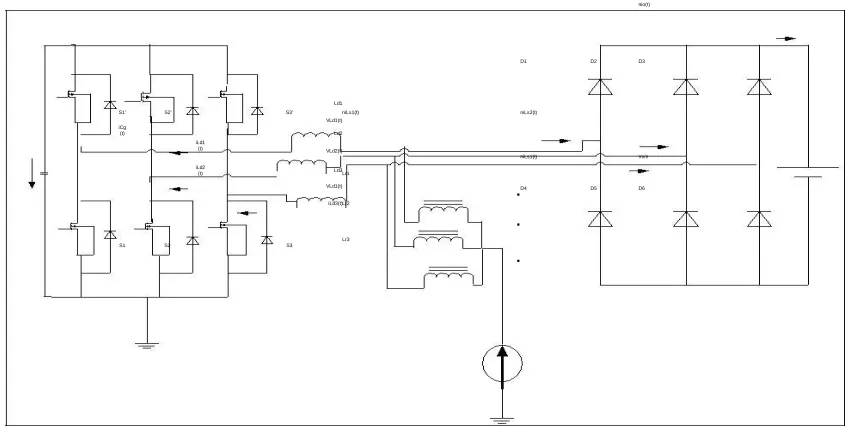
The analysis can be simplified maintaining the same waveforms using the Fig 2 despite the complete circuit being shown in Fig 1.[11]This circuit represents the non-isolated equivalent version of the proposed converter with current source input and voltage source output. The coupled three-phase reactor substitutes the transformer. The transformer was substituted by a coupled three-phase reactor.[12] The voltages and currents from the secondary side are referred to the primary side in this circuit. During the description of the operation stages, the time intervals related to the commutations will not be considered due to being very short and interfering very little in voltage gain.
nio(t)
D1 D2 D3
Ld1
S1' S2' S3' niLs1(t) niLs2(t)
VLd1(t) iCg (t) Ld2 iLd1 (t) VLd2(t) Vo/n niLs1(t)
iLd2(t) Ld3Lr1
VLd1(t)
.D4 D5 D6 iLd3(t)Lr2
.
Lr3
S1 S2 S3
.
Fig. 2.Simplified non-isolated version of the active-clamped three-phase current-fed push-pull DC-DC Converter
C. Modulation
This PWM technique approximates the reference voltage Vref by a combination of the eight switching patterns (V0 to
V7) Coordinate Transformation (abc reference frame to the stationary d-q frame): A three-phase voltage vector is transformed into a vector in the stationary d-q coordinate frame which represents the spatial vector sum of the three-phase voltage.[13]
The vectors (V1 to V6) divide the plane into six sectors (each sector: 60 degrees). Vref is generated by two adjacent non-zero vectors and two zero vectors.S1 to S3 and S1’ to S3’ are the six power switches that shape the output, which are controlled by the switching variables a, a′, b, b′, c and c′. When an upper transistor is switched on, i.e., when a, b or c is 1, the corresponding lower transistor is switched off, i.e., the corresponding a′, b′ or c′ is 0. Therefore, the on and off states of the upper transistors S1’, S2’ and S3’ can be used to determine the output voltage.[14-16]
A. Operation
The Proposed converter has nine topological stages per switching period that can be described as follows: Before the 1st stage; S1’, S2 and S3 are already conducting.
1] 1st stage (t0,t1) - This stage starts when switch s1 is turned on. Before this stage,S1’ was conducting and capacitor Cg was delivering energy. Current iLd1(t),initially negative and equal to -IL/3.It increases linearly through the
diode of S1 as shown in Fig. 4(a) becomes positive and the value increases through S1 until reaching IL/3 as shown in
Fig. 4(b). The currents iLd2(t) and iLd3(t) decreases from 2IL/3 to IL/3 through switches S2 and S3 respectively. The energy received by the load is from the commutation inductances through diodes D1,D5 and D6.The energy transfer from the source to load does not take place during this stage.[17]
2] 2nd stage(t1,t2) – This stage starts when the currents iLd1(t),iLd2(t) and iLd3(t) egual to IL/3.The currents
iLd1(t),iLd2(t) and iLd3(t) remain at IL/3 and the diodes of the rectifier remains in off condition. This is shown in Fig. 4(c). The energy is not transferred from source to load during this stage.
3] 3rd stage (t2,t3) – This stage starts when the switch S2 is turned off. The current iLd2(t) decreases linearly from
IL/3 through the diode of S2’ as shown in Fig. 4(d) and then it equals zero. It then starts to increase negatively until it
reaches –IL/3 as shown in Fig. 4(e). The energy from the commutation inductance is received by the clamping capacitor Cg as shown in Fig. 4(d). The capacitor Cg returns this energy asshown in Fig. 4(e). The currents iLd1(t) and iLd3(t)
increases from IL/3 to 2IL/3 through the switches S1 and S3 respectively. The source transfers the energy to the load through the diodes D2, D4 and D6.The fourth topological stage and the seventh topological stages are similar to the first stage. The fifth topological stage and eight topological stages are similar to the second stage. The sixth and ninth topological stages are similar to the third stage. The difference is that the other switches are on. The switching period is completed after the ninth stage and the new period starts with the first stage.
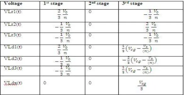
The main voltages of the circuit during the described stages are shown in Table II. The main theoretical waveforms for region R3 are shown in Fig.3, whose time intervals are described by equations as presented in Table III. The waveforms plotted on Fig. 4 and the voltages presented in Table II correspond to the symbols presented previously on Fig.1 and Fig. 2.
Table II Main Voltages during each topological stage
First stage . .
∆ 1 =
0
Second stage
∆ = − ∆ − ∆
2 3
1 3
Third stage ∆ = 1 − .
3
Fig.4.Main theoretical waveforms for region R3
Fig.6 Output voltage of ZVS-PWM three-phase current-fed push-pull DC-DC Converter
Fig.7 Output current of ZVS -PWM three-phase current-fed push-pull DC-DC Converter
Fig.9 Output current of the Space-Vector-PWM Three Phase current-fed Push Pull DC-DC Converter
Fig 6 shows output voltage of ZVS Sine-PWM three-phase current-fed push-pull DC-DC converter. The output voltage has been obtained as 400V. Fig 7 shows output current of ZVS Sine-PWM three-phase current-fed push-pull DC-DC Converter. The output current has been obtained as 9A but has ripples in it. Fig 8 shows output voltage of Space vector-PWM three-phase current-fed push-pull DC-DC Converter. The output voltage has been obtained as 700V. Fig 9 shows output current of ZVS Sine-PWM three-phase current-fed push-pull DC-DC Converter. The output current has been obtained as 6A but the ripples are reduced by using this technique and have got high output when compared with the Sine-PWM.Thus the advantages of Space vector PWM can be effectively utilized in this paper.[18]
V.
CONCLUSION
In this paper, a Space Vector –PWM Three phase Current-fed Push-Pull DC-DC Converter has been proposed. In this paper, a SV-PWM Three-Phase Current-Fed Push-Pull DC-DC Converter has been proposed.The operation stages were described and the main waveforms were plotted. The equations of voltage gain and equations involving the commutation parameters were derived to help the design process.
REFERENCES
[1]. R.Prasad, P.D.Ziogas, S.Manias, “Analysis and design of a three-phase off-line DC-DC converter with high frequency isolation,” in
Proc.IAS’88,1988,pp.813-820.
[2]Sukumaran V.G., Bharadwaj N., "Ceramics in dental applications", Trends in Biomaterials and Artificial Organs, ISSN : 0971-1198, 20(1) (2006) pp.7-11.
[3]L.D.Salazar, P.D.Ziogas, S.Manias, “Design oriented analysis of two types of three-phase high frequency forward SMR topologies”, in Proc.Fifth
Annual Applied Power Electronics Conference andExposition, APEC’90,11-16/Mar.,1990,pp.312-320
[4] Selva Kumar S., Ram Krishna Rao M., Balasubramanian M.P., "Chemopreventive effects of Indigofera aspalathoides on 20-methylcholanthrene
induced fibrosarcoma in rats", International Journal of Cancer Research, ISSN : ISSN: 1811-9727, 7(2) (2011) pp.144-151.
[5]R.W.A.A.De Doncker,D.M.Divan and M.H.Kheraluwala, “A three-phase soft-switched high-power-density DC/DC converter for high-power
applications”, IEEETrans.Ind.Applicat.,vol.27,pp.63-73,Jan/Feb.1991.
[6] Menon R., Kiran C.M., "Concomitant presentation of alopecia areata in siblings: A rare occurrence", International Journal of Trichology, ISSN : 0974-7753, 4(2) (2012) pp.86-88.
[7]J.Jacobs, A.Averberg and R.De Doncker, “A novel three-phase DC/DC converter for high-power applications” in Proc.Power Electronics
Specialists Conference,PESC 2004,Aachen,Germany,pp.1861-1867,vol.3.
[8]Rayen R., Hariharan V.S., Elavazhagan N., Kamalendran N., Varadarajan R., "Dental management of hemophiliac child under general anesthesia", Journal of Indian Society of Pedodontics and Preventive Dentistry, ISSN : 0970-4388, 29(1) (2011) pp.74-79.
[9]D.S.Oliveira Jr. and I.Barbi, “A three-phase ZVS PWM DC/DC converter with asymmetrical duty cycle for high power
applications”,IEEETrans.PowerElectron.,vol.20,n.2,pp.370-377,Mar.2005.
[10]Shanthi B., Revathy C., Devi A.J.M., Subhashree, "Effect of iron deficiency on glycation of haemoglobin in nondiabetics", Journal of Clinical and Diagnostic Research, ISSN : 0973 - 709X, 7(1) (2013) pp.15-17.
[12]D.Segaran,D.G.Holmes and B.P McGrath, “Comparative analysis of single and three-phase dual active bridge bidirectional DC-DC-DC
converters” in Proc. Australasian Universities Power EngineeringConference,2008,AUPEC’08,Sydney,NSW,Australia,Dec.2008,pp.1-6.
[13]J.Aguillon-Garcia and G.W.Moon, “A High Efficiency Three-Phase ZVS PWM Converter Utilizing a Positive Double-Star Active Rectifier
Stage for Server Power Supply”,IEEETrans.Ind.Electronics,vol.58, no.8,pp.3317-3329,Aug.2011.
[14]D.Vinnikov and I.Roasto, “Quasi-Z-Source-Based Isolated DC/DC Converters for Distributed Power Generation”, IEEE Trans. Ind. Electronics,
vol.58, no.1,pp.192-201,Jan.2011.
[15]S.V.G.Oliveira and I.Barbi, “A three-phase step-up DC-DC converter with a three-phase high frequency transformer” inProc.571-576 vol.2.
IEEE International on Industrial Electronics, ISIE2005,Dubrovnik,Croatia,June 2005,pp
[16]R.L.Anderson and I.Barbi,“A Three-Phase Current-Fed Push-Pull DC-DC Converter”,IEEE Trans Power Electron.,vol.24,no.2,pp.358-368,Feb.2009.
[17]Romero L.Andersen and Ivo Barbi, , “A ZVS-PWM Three-Phase Current-Fed Push-Pull DC-DC Converter”,IEEE 2011. [18] Hima Sudev and M.Murugan soft switching three phase push-pull DC-DC Converter using Space-
Vector PWM
[19] B.Vamsi Krishna, A New Technique for Elimination of Harmonics Using Three Phase Shunt Active Filter, International Journal of Advanced
Research in Electrical, Electronics and Instrumentation Engineering, ISSN (Online): 2278 – 8875,pp 5596-5602, Vol. 2, Issue 11, November 2013
[20] P.Thamarai, B.Karthik, ARM Based Automatic Meteorological Data Acquisition System, International Journal of Advanced Research in
Electrical, Electronics and Instrumentation Engineering, ISSN (Online): 2278 – 8875,pp 6461-6465, Vol. 2, Issue 12, December 2013
[21] M.Bharathi,Effective Transfer Function Approach for Decentralized Controller,International Journal of Advanced Research in Electrical,
Electronics and Instrumentation Engineering, ISSN 2278 - 8875 , pp 21-27, Vol. 1, Issue 1, July 2012.
[22] Vijayan T ,Energy-efficient MAC for Wireless Sensor Networks,International Journal of Advanced Research in Electrical, Electronics and
Instrumentation Engineering,ISSN 2278 - 8875, pp 51-57,Vol. 1, Issue 1, July 2012.