ISSN (Print) : 2320 – 3765 ISSN (Online): 2278 – 8875
I
nternational
J
ournal of
A
dvanced
R
esearch in
E
lectrical,
E
lectronics and
I
nstrumentation
E
ngineering
(An ISO 3297: 2007 Certified Organization)
Vol. 4, Issue 12, December 2015
Performance of an Uplink OFDMA
System Using Subcarrier Allocation
Shalini J
1, Dr.Y.R.Manjunatha
2Assistant Professor, Department of ECE, KSSEM, Bangalore, India1
Associate
Professor, Department of EEE, UVCE, Bangalore University, Bangalore,India
2ABSTRACT: OFDMA (Orthogonal Frequency Division Multiple Access) suffers from destruction of orthogonility if a channel betweenthe
mobile user and a base station is rapidly time varying. This channel between the mobile user and a base station is called an Uplink-OFDMA. The OFDMA uplink resource allocation undergoes from Inter carrier interference (ICI), multiuser interference (MUI) if a nearby subcarrier is assigned to different user, high peak to average power ratio (PAPR) and high bit error rate (BER).This results in performance degradation. In order to provide a significant improvement in performance, a practical OFDMA system detection is required. The proposed system consists of a new sub-carrier allocation method using a successive interference cancelation (SIC) detector at the receiver side. The proposed system is designed and simulated using MATLAB tool.
Simulation results show that the proposed subcarrier allocation and ―Interleaved Aǁ allocation method has an average Bit error
probability of 10 -0.5 and 10-0.2 respectively. Thus Average Bit error probability of around 32% is reduced compared to the ―Interleaved Aǁ
allocation method. Further, simulations also demonstrate a gradual decrease in MUI power from -15db to -20db for interleaved allocation and subcarrier allocation method respectively.
KEYWORD: BER, PAPRR, ICI, SIC
I. INTRODUCTION
Orthogonal frequency division multiplexing (OFDM) is a modulation method that divides a channel into multiple narrow orthogonal bands that are spaced so they don’t interfere with one another. Each band is divided into hundreds or even thousands of wide subcarriers. To save the bandwidth, frequencies are made orthogonal to each other, and thus the name orthogonal frequency division multiplexing.
Time slots within each subchannel data stream are used to package the data to be transmitted. Two conditions must be considered for the orthogonality between the subcarriers: Each subcarrier has precisely an integer number of cycles in the FFT interval. The number of cycles between adjacent subcarriers differs by exactly one.
The objective of this paper is to find a resourceful subcarrier allocation algorithm that can improve the performance of an uplink-OFDMA under a nonhomogeneous user environment without increasing the transceiver complexity much. To achieve this objective, all users are classified into three groups: a vehicular users’ group of relatively fast-moving users, slow users and a pedestrian users’ group of relatively stationary users. Only the vehicular users are assumed to generate the ICI and MUI due to the higher Doppler spreads. Then, the successive interference cancelation (SIC) with a one-tap equalizer becomes a practical candidate, if it can eliminate the ICI and MUI from the vehicular users without error propagation.
Assuming a SIC detector, we state a mutual interference power among the subcarriers allocated to the vehicular users, and formulate
,
an integer programming to find an optimum subcarrier allocation that minimizes the maximum mutual interference power. Applying a continuous relaxation of the derived integer programming, which becomes a convex programming, a suboptimal algorithm is proposed using the Karush-Kuhn-Tucker (KKT) conditions [11]. Finally, the average bit error rate (BER) with respect to all users will be simulated to show the greater performance of the proposed allocation scheme over the existing schemes in a convolutional coded uplink-OFDMA system.II. SYSTEM MODEL
Assume that N total number of subcarriers are allocated to U number of uplink users equally, i.e., N = UC, where C is the number of subcarriers per user.
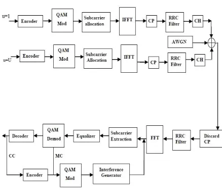
Fig 2.1 Proposed Block diagram of transmitter and receiver for uplink OFDMA
Also the robustness of the proposed scheme against low quality Doppler spread information is shown. In other words, demonstrate through simulation that even if a Doppler spread frequency of each user is quantized into a 2-class, significant performance improvement can still be observable. Hence, the proposed subcarrier allocation method can be effective even with low complexity, i.e., binary Doppler spread frequency feedback information. Figure 2.1 shows a simplified block diagram of the transmitter and receiver for an uplink-OFDMA system.
In the transmitter of each user, a stream of information bits is fed into an encoder and then modulated by a quadrature amplitude modulation (QAM). The modulated symbols are assigned to the subcarriers. Define a set of subcarriers allocated to user u and an N×1 transmitted vector of dimension u as ku and xu, respectively. The entry of xu denoted by xu (i), is a transmitted QAM symbol if i Є ku, and 0 otherwise.
III. SUBCARRIER ALLOCATION ALGORITHM.
After taking an inverse fast Fourier transform (IFFT) using xu, a cyclic prefix (CP) is appended to each OFDM symbol to avoid the ICI and
intersymbol interference (ISI) due to the multipath dispersion.
At the receiver in the base station, the CP is discarded and a fast Fourier transform (FFT) is performed. Then, the received signal for the k-th subcarrier can be written as
where w(k) is a zero-mean additive white Gaussian noise (AWGN) of σ2, and Hu (k, i) is given by
Where, hu (n,m) is the channel impulse response (CIR) at the m
th
lag and the n th instant for the uth user and it is modeled as an independent stationary Gaussian process with E{hu(n ,l)}=0 and ∑L-1 E{ |hu (n, l)|2 }
ISSN (Print) : 2320 – 3765 ISSN (Online): 2278 – 8875
I
nternational
J
ournal of
A
dvanced
R
esearch in
E
lectrical,
E
lectronics and
I
nstrumentation
E
ngineering
(An ISO 3297: 2007 Certified Organization)
Vol. 4, Issue 12, December 2015
Fig. 3.1 Subcarrier allocation for vehicular users, and corresponding user sequence and distance sequence.
Equivalent users-sequence and distance-sequence: O = (1, S, 2, S,…1,4,…3,S) D = (d1,d2,…d3,…dq…dsc)
Since there are too many possible candidates in user sequence O as well as in the integer distance sequence D= ( , it is difficult to find an optimum subcarrier allocation. Therefore, we propose a two-stage sub-optimal algorithm: In the first stage, a proper user sequence O is determined for the SIC detector, and in the second stage, the optimum distance sequence D of dq is computed for a given sequence O. Because the SIC detector can detect and cancel the interference generated by the faster -moving users prior to the slower ones, it is desirable to design a user sequence such that the faster-moving users have less interference, i.e., the neighbors of a subcarrier allocated to a faster-moving user should be assigned to a slower user. Keeping this fundamental assignment criteria in mind over the entire sequence search, we count the number of remaining subcarriers that are not assigned in the sequence, and choose a faster (or slower) moving user of the maximum number of remaining subcarriers to be allocated. In each step of the first stage, we find all users whose number of remaining subcarriers to be allocated.
IV. NUMERICAL RESULTS
A practical OFDMA system with following specifications is used for simulation purpose in MATLAB tool.
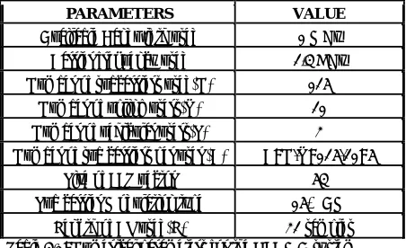
The numerical specifications/parameters for the OFDMA system is as given below in the table An available1MHz bandwidth is divided into 128 tones with 32 time samples for CP, where N =126,and two edge subcarriers are not used. Specifications used for project as shown in table 4.1. Simulation of many physical processes and engineering applications often require the help of a generator of random binary values.
PARAMETERS VALUE
Available Bandwidth used 1 MHz Carrier frequency used 2.4 GHz Number of subcarriers used(N) 126
Number of uplink users(U) 21 Number of vehicular users(S) 3 Number of sub carriers per user (C) C=N/U=126/21=6
Size of FFT vector 64 Sub carrier Modulation type 16-QAM
Length of CP used(L) 32 samples Table 4.1: Numerical parameters for the OFDMA system
Figure 4.1: Input binary data generation for OFDMA system
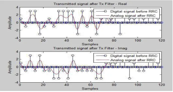
The next step is to produce a continuous-time signal. In order to achieve this, a transmit filter-Root rise cosine filter is applied to the complex signal carriers. The figure below shows the generated continuous time signal. The figure 4.2 shows the generated continuous time signal.
In the next step they are transferred in an OFDM link by using a modulation scheme on each subcarrier. The modulation scheme used here is 16-QAM. The modulation scheme is a mapping of data to a real (IN phase) and imaginary (Quadrature) constellation, also known as an IQ constellation.
Figure 4.2: Real and imaginary parts of continuous time signal generated by RRC filter
In OFDM an IFFT is used to put the binary numbers onto many frequencies. Due to the math involved in an IFFT, these frequencies do not interfere with each other, (in communication terms, this is called orthogonality). The QAM mapped output obtained with ideal channel as shown in fig 4.3. The eye pattern is created by taking the time domain signal and overlapping the traces for a certain number of symbols. The vertical eye opening or noise margin is related to the SNR and the horizontal eye refers to jitter and sensitivity.
ISSN (Print) : 2320 – 3765 ISSN (Online): 2278 – 8875
I
nternational
J
ournal of
A
dvanced
R
esearch in
E
lectrical,
E
lectronics and
I
nstrumentation
E
ngineering
(An ISO 3297: 2007 Certified Organization)
Vol. 4, Issue 12, December 2015
Figure 4.3 QAM mapped output obtained with ideal channel
The QAM constellation mapped output adding noise is simulated as shown in fig 4.4. Once the signal is received, the reverse process is done to recover the original binary data. The constellation demapper takes packets of received constellation points as an input, and outputs data.
Figure 4.4 QAM mapped output obtained after adding AWGN channel
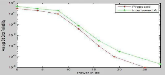
The average BER performance over all users data is found by simulation of the proposed algorithm.
The bit error rate or bit error ratio (BER) is defined as the ratio of the number of bit errors to the total number of transferred bits during a time interval.In this work, in addition to the proposed subcarrier allocation algorithm, one more method called “interleaved A” is simulated for comparison purpose.
The first allocation method, called “Interleaved A” assigns to user vj the subcarriers whose indices are equal to (j) U where (·) U is the modulus operator, regardless of the Doppler frequency information. The proposed new sub carrier allocation algorithm takes into effect of normalized Doppler frequencies. The Bit error rate of the two algorithms is compared and the new designed sub carrier allocation algorithm proves to be having less BER than the existing “Interleaved A” algorithm as shown in the figure 4.5.
.
Figure 4.6: MUI simulated for interleaved a and interleaved b and proposed sub carrier allocation
.
The MUI plotted below shows the gradual decrease in the power consumed for the various numbers of users having sub carrier allocated
.
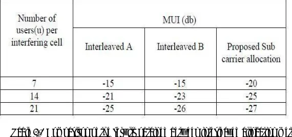
Simulation results show that the proposed subcarrier allocation and “Interleaved A” allocation method has an average Bit error probability of 10-0.5 and 10-0.2 respectively. Thus Average Bit error probability of around 32% is reduced compared to the “Interleaved A” allocation method. For the accurate analysis, two new allocation algorithm known as “Interleaved A” and "Interleaved B” methods have been simulated and compared with the proposed sub carrier allocation algorithm for the MUI parameter. The simulated graph of MUI expressed in power is db.In the “Interleaved A” allocation method, since the vehicular users can be assigned to the adjacent subcarriers, MUI does not decrease, regardless of the number of total users U=21.The second allocation called “Interleaved B,” randomly assigns the first U number of subcarriers to each user one by one, and this allocation pattern is repeatedly used for the remaining subcarriers, also regardless of the Doppler frequency information. Due to the randomness of the “Interleaved B” allocation method, MUI slightly decreases as shown in the fig 4.6
Table 4.2 Comparison of the results obtained between interleaved allocation method and proposed allocation method for different Users.
Simulation results show that the proposed subcarrier allocation and “Interleaved A” allocation method has an average Bit error probability of 10 -0.5 and 10-0.2 respectively. Thus Average Bit error probability of around 32% is reduced compared to the “Interleaved A” allocation method. Further, simulations also demonstrate a gradual decrease in MUI power from -15db to -20db for interleaved allocation and subcarrier allocation method respectively.
V CONCLUSION
This paper proposed an effective subcarrier allocation scheme for an uplink-OFDMA system to reduce the effects of ICI and MUI due to Doppler spreads.
Furthermore, it was found through numerical simulations that the proposed method is robust against the inaccurate Doppler-frequency estimation. Therefore, the proposed method can be useful for current and future wireless communication systems that may allow a classification of users into low, medium, and high velocities by counting the number of handovers.
ISSN (Print) : 2320 – 3765 ISSN (Online): 2278 – 8875
I
nternational
J
ournal of
A
dvanced
R
esearch in
E
lectrical,
E
lectronics and
I
nstrumentation
E
ngineering
(An ISO 3297: 2007 Certified Organization)
Vol. 4, Issue 12, December 2015
REFERENCES
[1]Phil. Trans. Roy. Soc. London, vol. A247, pp. 529–551, April 1955. (references)
[2] R. Fantacci, D. Marabissi, and S. Papini, “Multiuser interference cancellation receivers for OFDMA uplink communications with carrier frequency offset,” in Proc. 2004 IEEE Globecom, pp. 2808–2812.
[3] X. Cai and G. B. Giannakis, “Bounding performance and suppressing intercarrier interference in wireless mobile OFDM,” IEEE Trans. Commun.,,vol. 51, no. 12, pp. 2047–2056, Dec. 2003.
[4] P. Schniter, “Low-complexity equalization of OFDM in doubly selective channels,” IEEE Trans. Signal Process., vol. 52, no. 4, pp. 1002–1011,Apr. 2004.
[5] K. Fang, L. Rugini, and G. Leus, “Low-complexity block turbo equalization for OFDM systems in time-varying channels,” IEEE Trans. Signal Process., vol. 56, no. 11, pp. 5555–5566, Nov. 2008.
[6] A. Stamoulis, S. N. Diggavi, and N. Al-Dhahir, “Intercarrier interference in MIMO OFDM,” IEEE Trans. Signal Process., vol. 50, no. 10, pp.2451– 2464, Oct. 2002.
[7] Y. Zhao and S. H¨aggman, “Intercarrier interference self-cancellation scheme for OFDM mobile communication systems,”IEEE Trans. Commun.,vol. 49, no. 7, pp. 1185–1191, July 2001.[8] IEEE 802.16 TGe Working Document, (Draft Standard) - Amendmentfor physical and medium access control layers for combined fixed and mobile operation in licensed bands, 802.16e/D4, Aug. 2004.
[9] C. Y. Wong, R. S. Cheng, K. B. Letaief, and R. D. Murch,“Multiuser OFDM with adaptive subcarrier, bit, and power allocation,” IEEE J. Sel.AreasCommun., vol. 17, pp. 1747–1758 Oct. 1999.
[10] H. Saeedi-Sourck, Y. Wu, J. W. M. Bergmans, S. Sadri, and B.
Farhang-Boroujeny, “Complexity and performance comparison of filter bank multicarrier and OFDM in uplink of multicarrier multiple access networks,” IEEETrans. Signal Process., vol. 59, no. 4, pp. 1907–1912, Apr. 2011.
[11] S. Boyd and L. Vandenberghe, Convex Optimization. Cambridge Univeristy Press, 2004.
[12] Y. Mostofi and D. C. Cox, “ICI mitigation for pilot-aided OFDM mobile systems,” IEEE Trans. Wireless Commun., vol. 4, no. 2, pp. 765–774, Mar.2005.
[13] M. T. Heath, Scientific Computing. McGraw-Hill, 2005.
[14] K. Kim, H. Park, and H. M. Kwon, “Rate-compatible SFBC-OFDMunder rapidly time-varying channels,” IEEE Trans. Commun., vol. 59,no. 8, pp. 2070– 2077, Aug. 2011.